08/04/2024 19:51:42
车载电脑 (HW4)(拆卸和安装)
 校正代码
21151031
0.84
注意:除非本程序中另有明确规定,否则上述校正代码和 FRT 反映的是执行本程序(包括关联程序)所需的所有工作。除非明确要求,否则请勿堆叠校正代码。
注意:请参阅平均维修工时,深入了解 FRT 及其创建方式。要提供有关 FRT 值的反馈,请发送电子邮件至LaborTimeFeedback@tesla.com。
注意:请参阅人员保护,确保在执行以下程序时穿戴适当的个人防护装备 (PPE)。
校正代码
21151031
0.84
注意:除非本程序中另有明确规定,否则上述校正代码和 FRT 反映的是执行本程序(包括关联程序)所需的所有工作。除非明确要求,否则请勿堆叠校正代码。
注意:请参阅平均维修工时,深入了解 FRT 及其创建方式。要提供有关 FRT 值的反馈,请发送电子邮件至LaborTimeFeedback@tesla.com。
注意:请参阅人员保护,确保在执行以下程序时穿戴适当的个人防护装备 (PPE)。
- 2024-04-02: Added torque specification for the bolts that attach the car computer to the bulkhead, and added a step for the installation of such bolts.
- For HW3 car computer, use correction code 21151001
警告
尽管此程序已经过验证,但仍是一个草案。可能没有警告和注意事项。请遵守安全要求,处理或靠近高压系统和部件时,请谨慎操作。请将校正修理内容及反馈发送至ServiceDevelopment@teslamotors.com。
拆卸
- Open the LH front door.
- Lower the LH front window.
- Open the RH front door.
- Lower the RH front window.
-
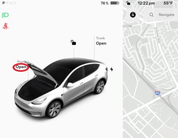
Open the hood.
-
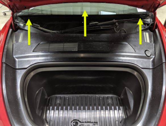
Remove the rear apron.
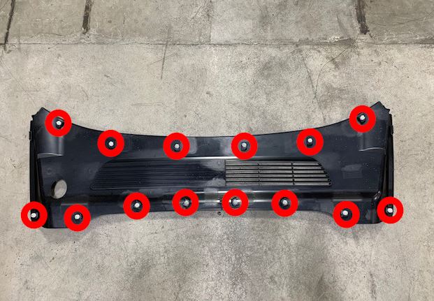
-
Power off the vehicle using the
touchscreen.
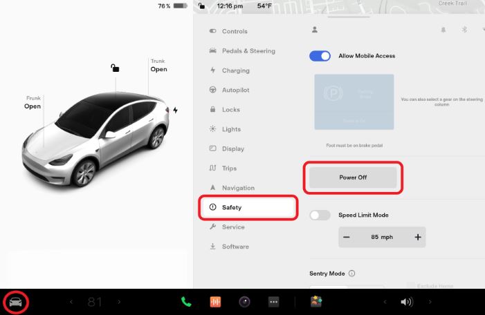
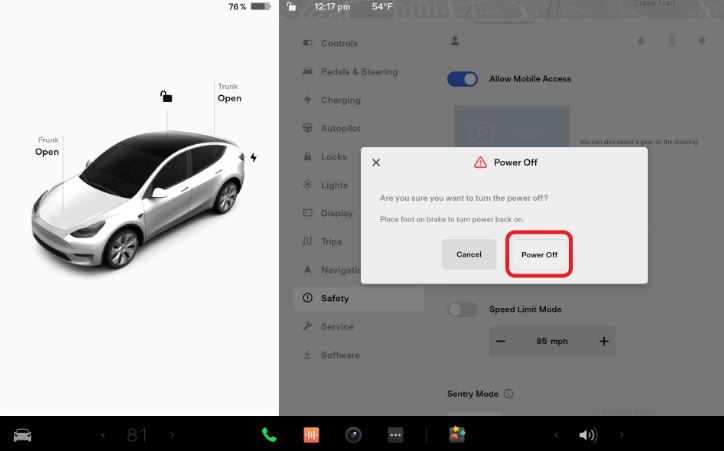
-
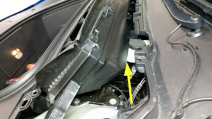
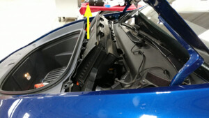
Remove HEPA filter assembly
注2x bolts, 10mm, 5 Nm, Pivot rearward edge up and past brake reservoir, Then lift up to clear frunk assembly
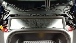
-
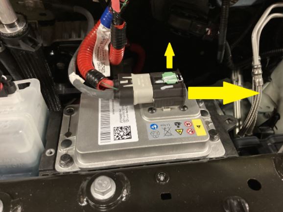
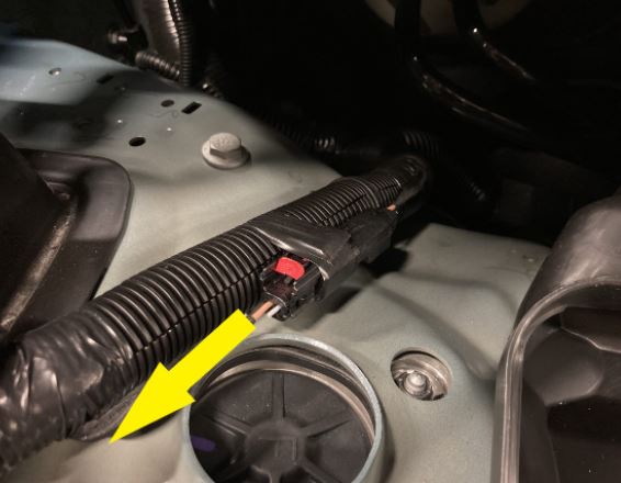
Disconnect the LV battery connector
and First Responder Loop.
-
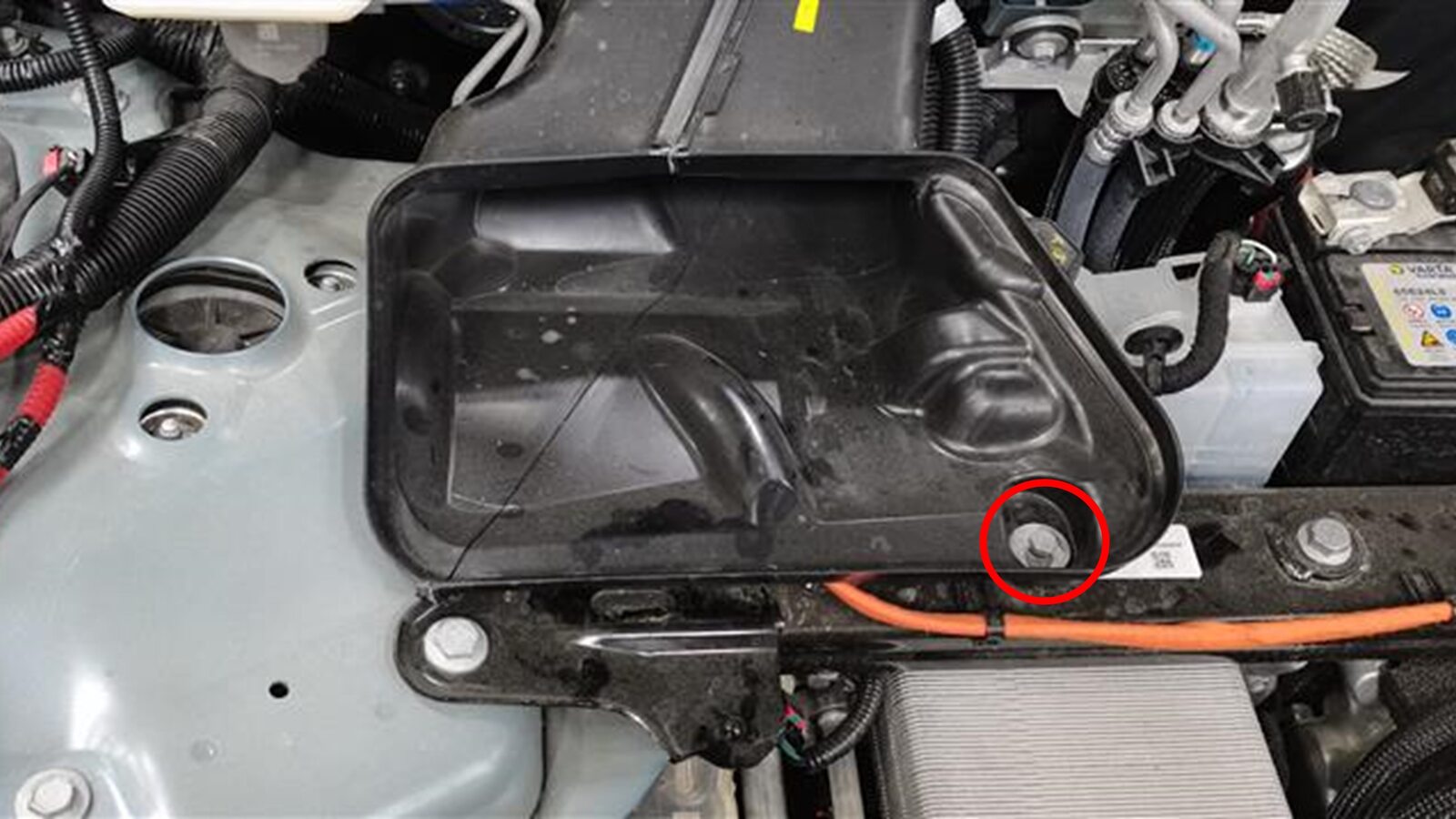
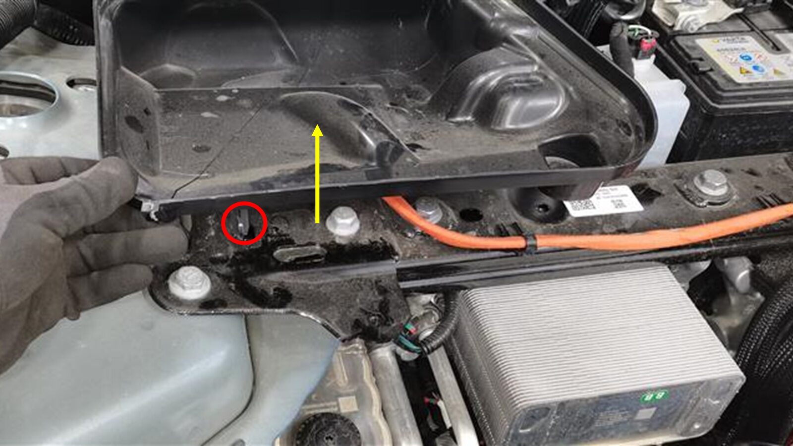
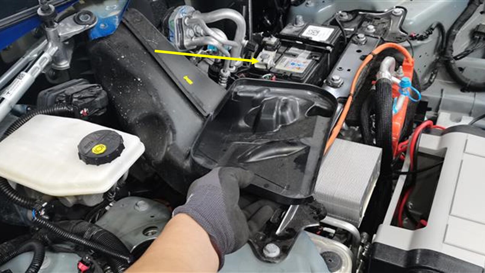
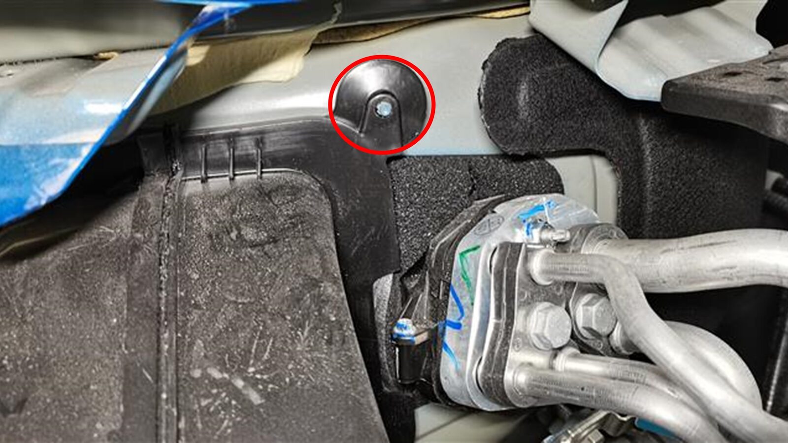
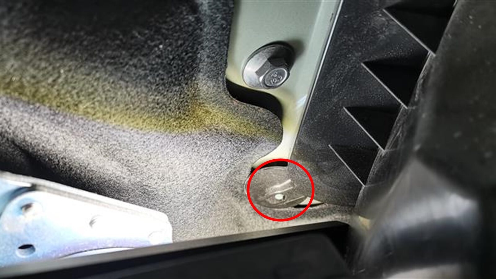
Remove fresh air intake duct
注1x bolt, 10mm, 4 Nm, 2x clips, 1x pin, Remove bolt, Gently pry pin out from thermal beam, then remove from bulkhead studs
-
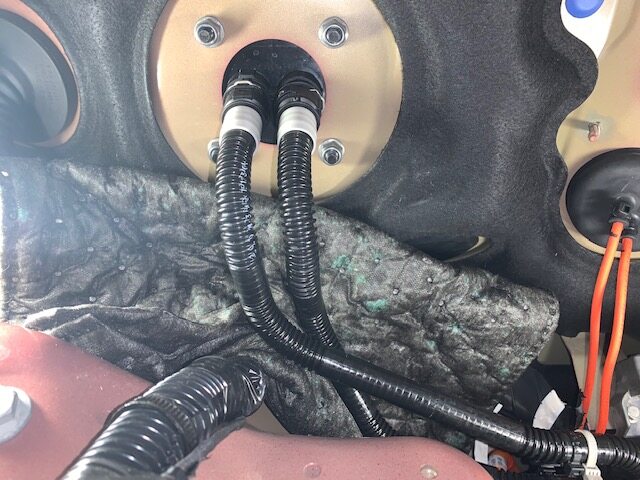
Place absorbent material below car
computer coolant hose connection points to collect any spilled coolant
-
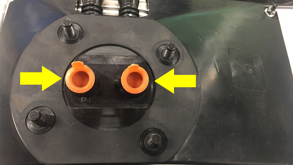
Remove car computer coolant plugs from
new car computer
注2x coolant plugs
-
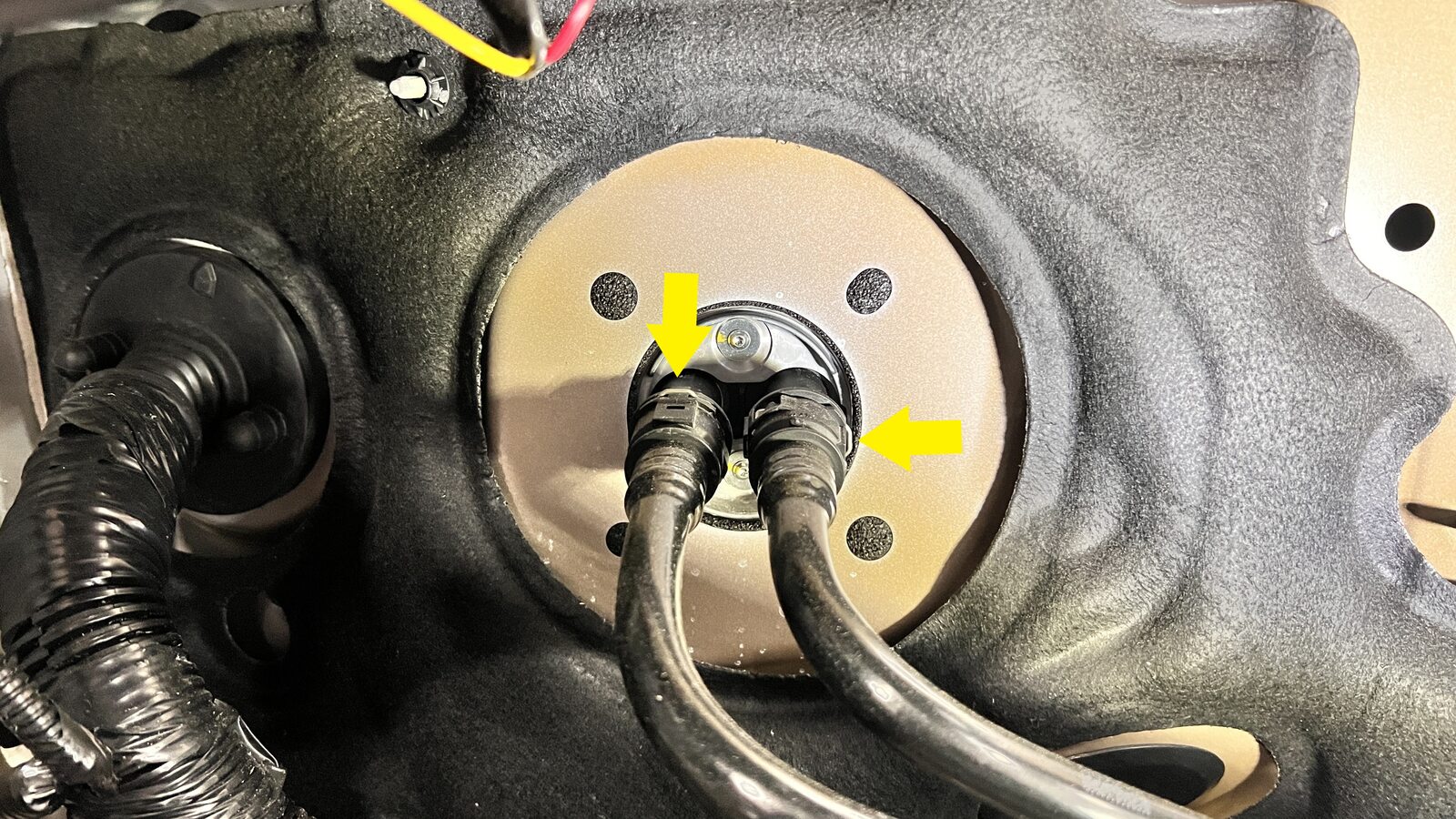
Release coolant hoses from car
computer
注2x spring clips
-
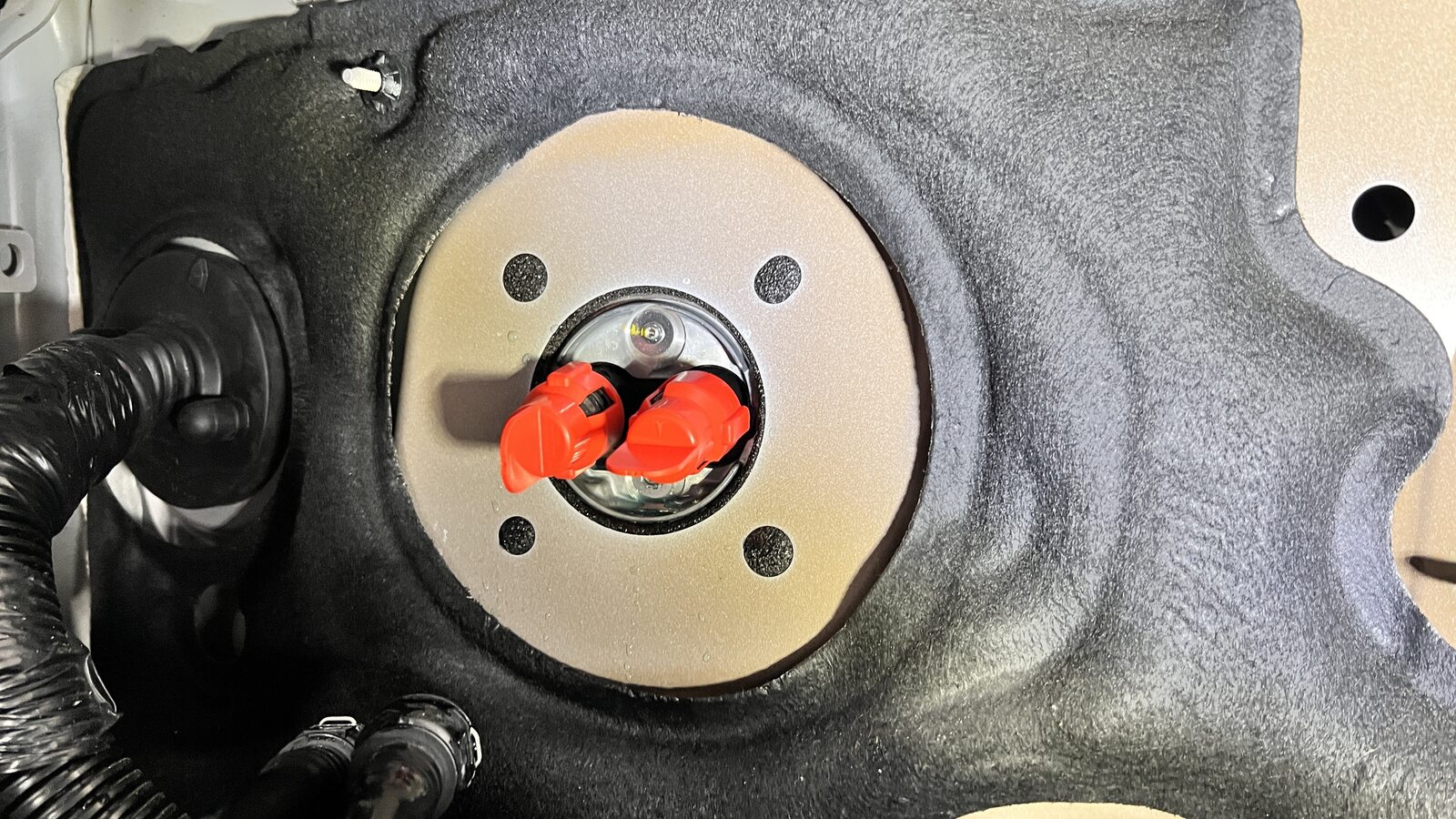
Install coolant plugs into coolant
outlets of car computer that is being removed from vehicle
-
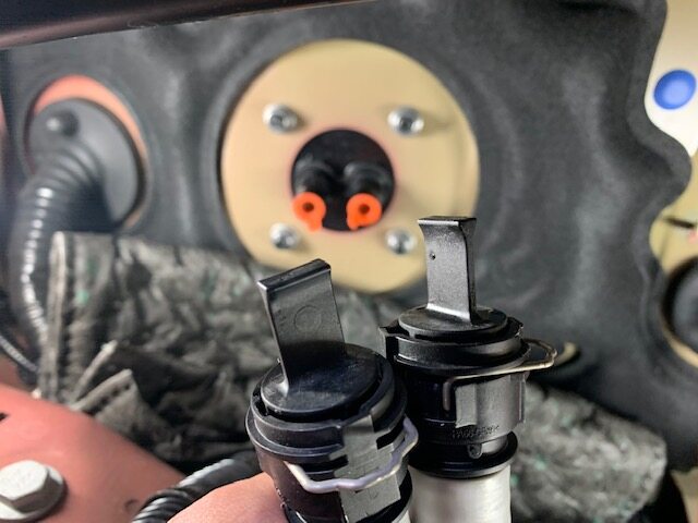
Install plugs to car computer coolant
hoses
注2x plugs, Do not need to engage spring clips
-
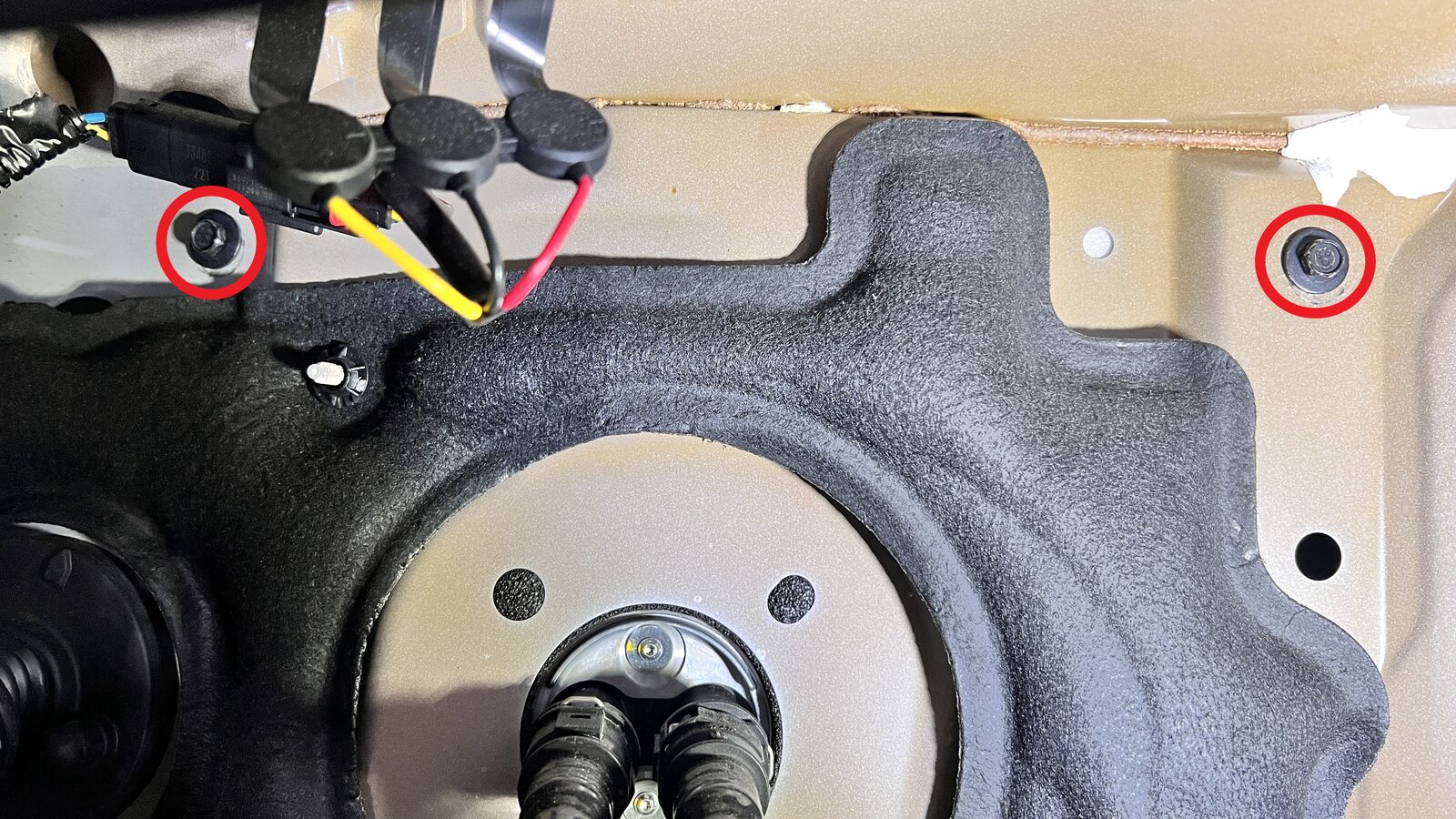
Remove the bolts (x2) that attach the
car computer to the bulkhead.
注13 mm, 15 Nm
-
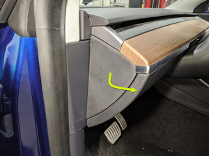
Remove LH IP end cap
注3x clips
-
Remove RH IP end cap
注3x clips
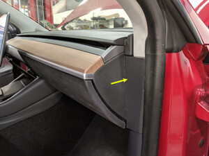
-
Remove RH mid A-pillar assembly
注1x clip, 1x tab, Release the upper clip then pull mid A-pillar upward to remove
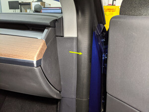
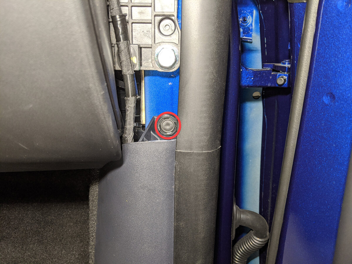
-
Remove clip securing RH lower A-pillar
trim
注1x push clip
-
Remove RH lower A-pillar trim
注6x clips, 2 guide tabs, Pull rear of lower A-pillar upward to release clip then pull rearward to release trim panel
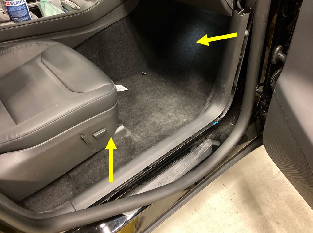
- Move the RH front seat back.
-
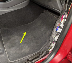
Remove RH front floormat
-
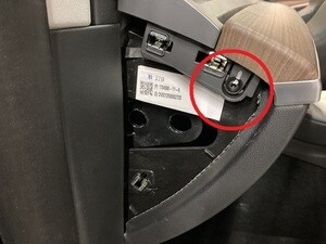
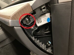
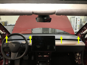
Remove main decor assembly
注2x screws, T20, 2.3 Nm, 15x clips, 1x center clip, Replace securing clips as needed
-
Release RH footwell assembly from
IP
注1x screw, T20, 1.2 Nm, 1x push clip, 8x tabs, carefully pull out to release tabs
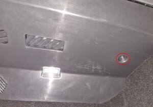
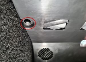
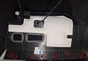
-
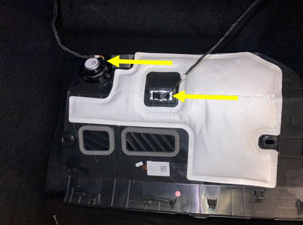
Remove RH footwell assembly
注2x connectors
-
Remove fasteners securing passenger
knee air bag to vehicle
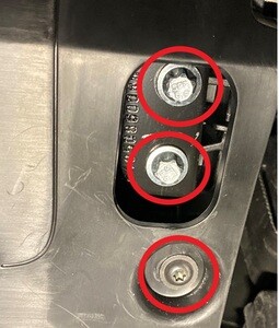
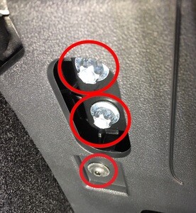
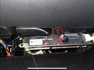
注2x screws, T20, 2 Nm, 1x push clip, 4x patch bolts, E10, 8 Nm, Discard patch bolts after removal, Support the knee air bag while lowering, The connector / harness length is very short
-
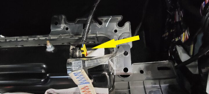
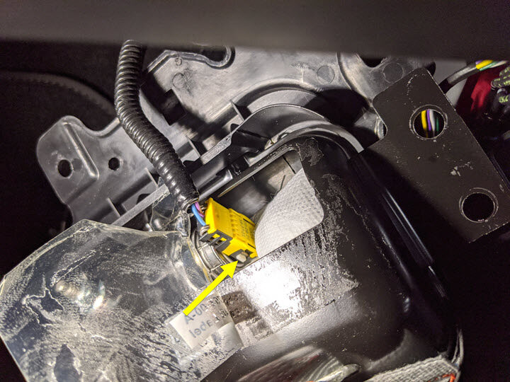
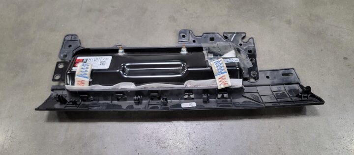
Remove passenger knee air bag
注1x connector, Release locking tab, Then release squib from air bag, Support air bag while disconnecting, Connector release may vary
-
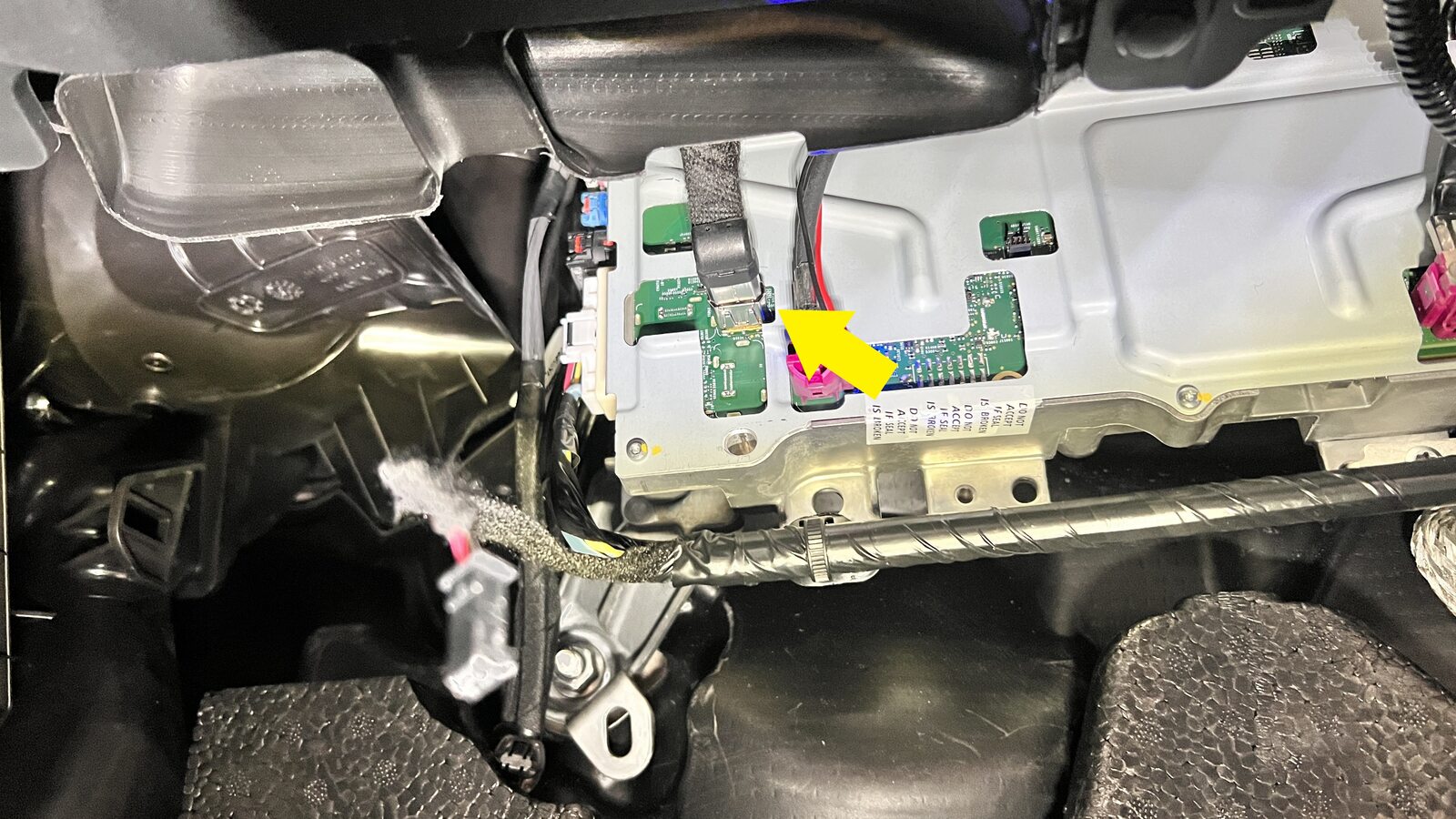
Disconnect glove box USB cable from
car computer
注1x connector, Depress latch on top of USB cable to release internal latches, then release from car computer.
-
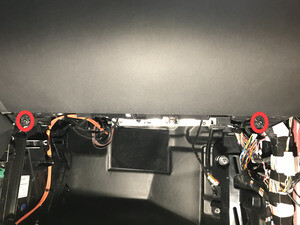
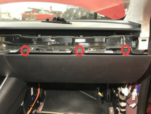
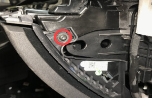
Remove screws securing glove box
assembly to IP carrier
注6x screws, T20, 2.3 Nm
-
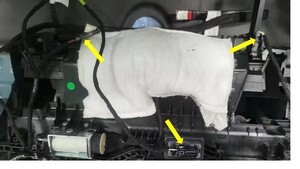
Disconnect glove box assembly
connectors
注3x connectors
-
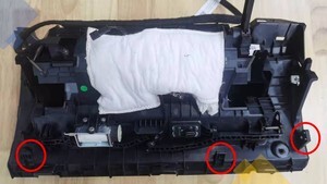
Remove the glove box from IP
carrier
注3x clips
-
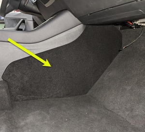
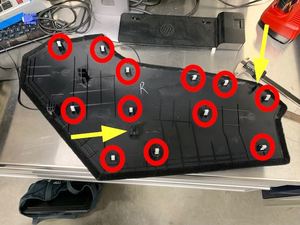
Remove RH console side panel
carpet
注12x clips, 2x locating pins, Use trim tool starting at top edge to release upper clips, Pull bottom to release remaining clips, Use caution and pull panel straight away from console, if panel is peeled off it could be damaged
-
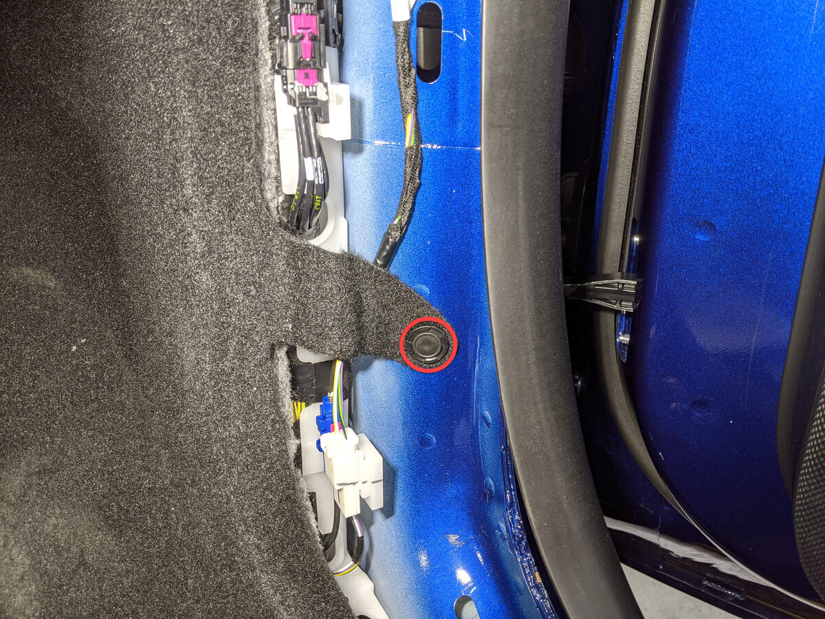
Remove clip securing RH front cabin
carpet to body
注1x clip
-
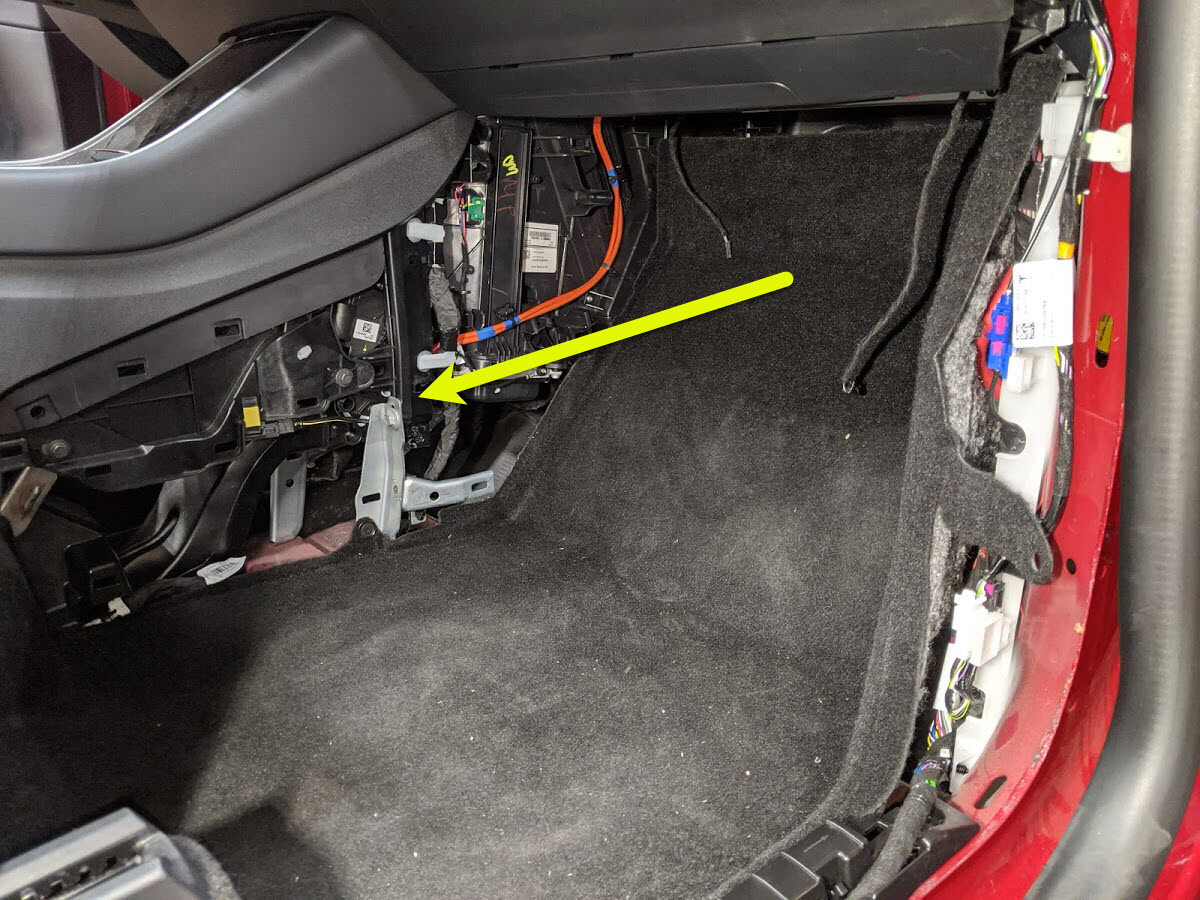
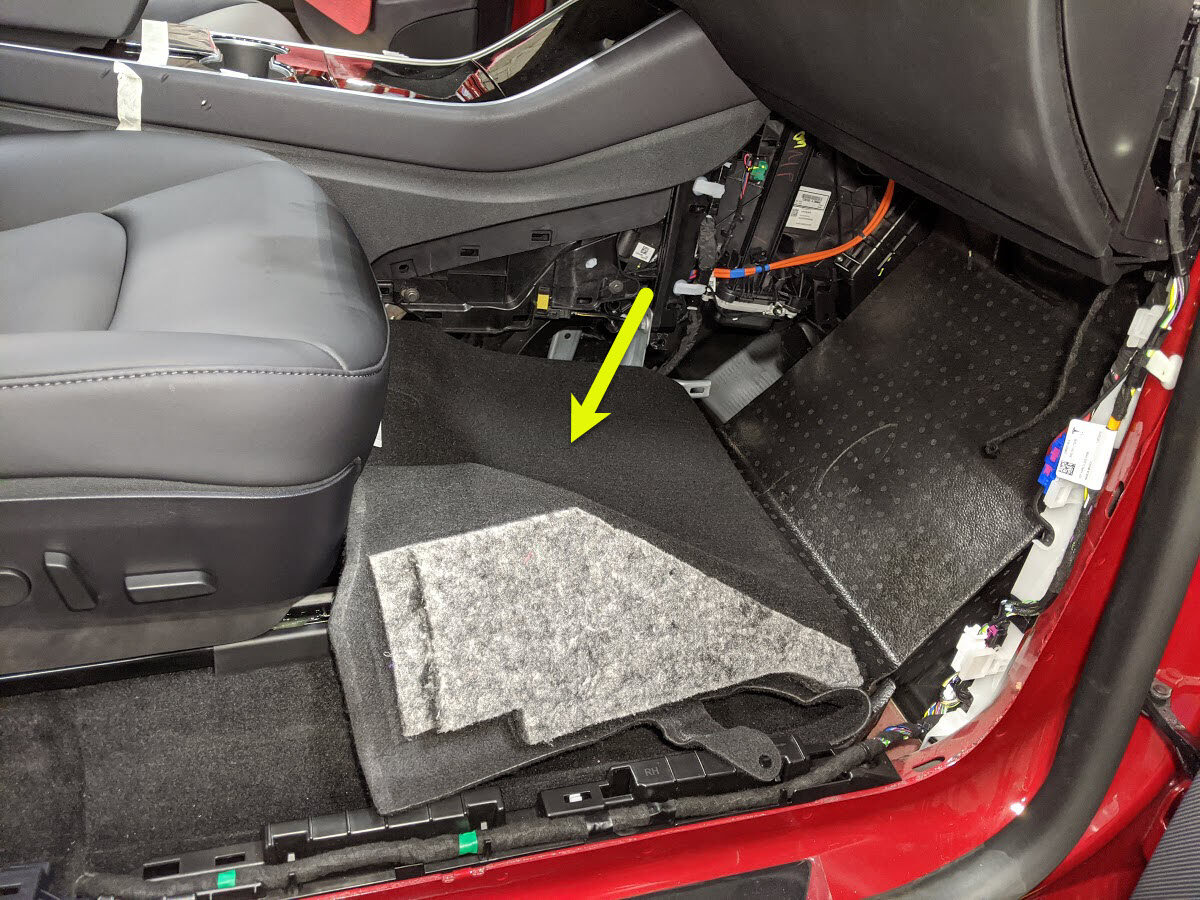
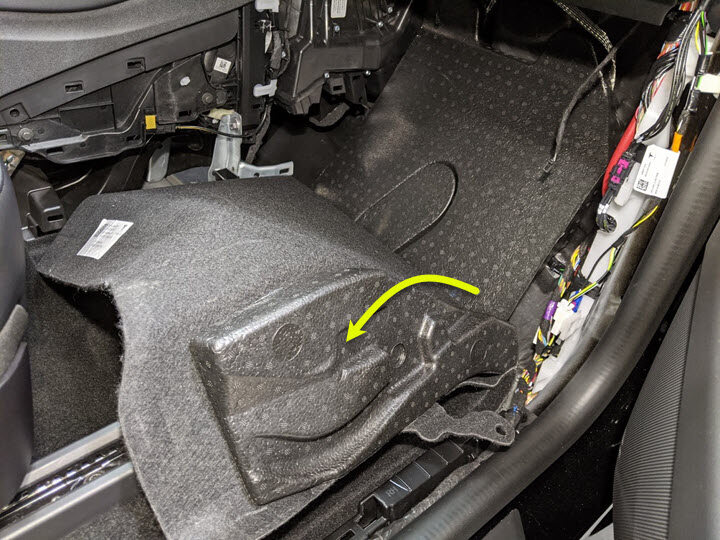
Fold RH front cabin carpet
rearward
注Newer VINs may be equipped with additional foam installed below carpet
-
Remove the passenger footwell air
duct
注1x push clip

-
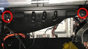
Remove the RH IP air wave duct
注2x push clips
-
Release ground strap from car
computer
注1x bolt, T25, 4 Nm, Bolt located, Discard bolt after removal

-
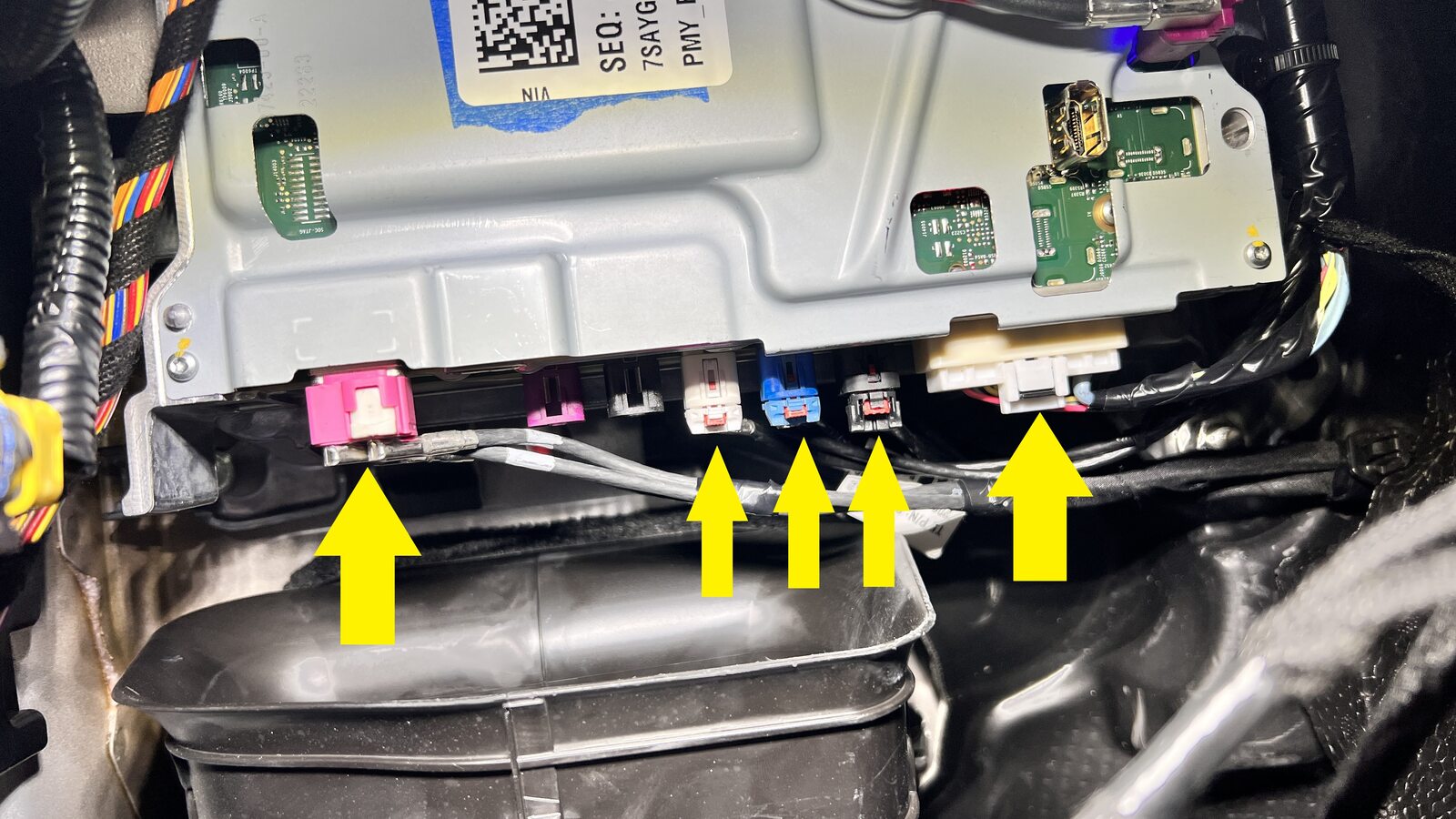
Release connections at LH side of car
computer
注5x connectors, Release locks on connectors before removal
-
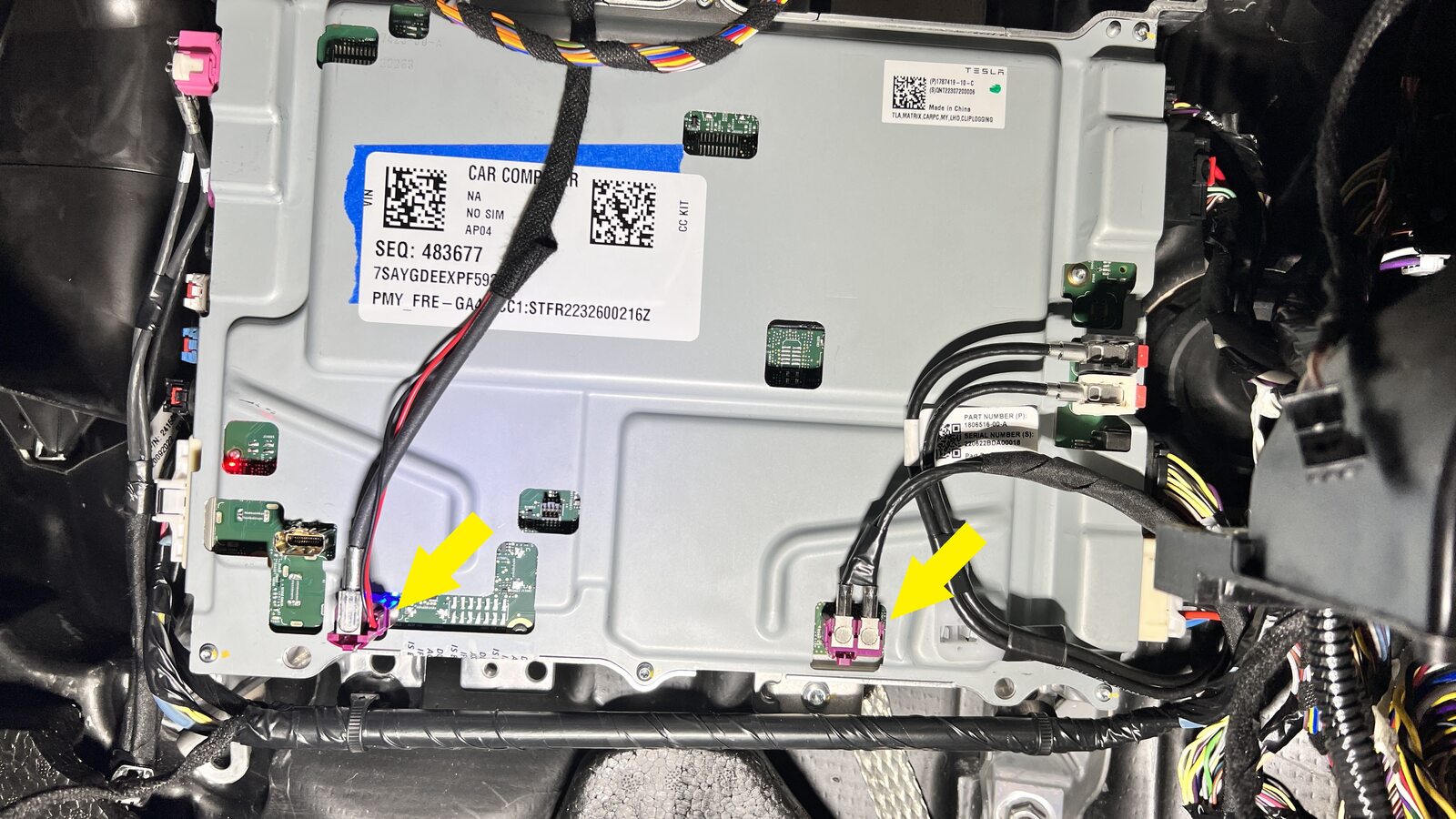
Disconnect connectors on front side of
car computer
注2x connectors
-
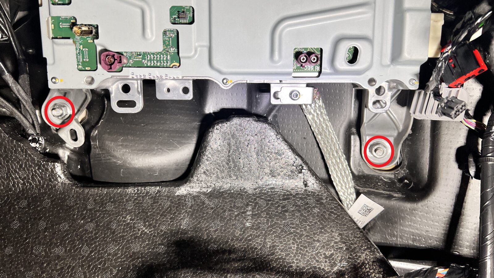
Remove car computer mounting
fasteners
注2x nuts, 13mm, 8 Nm
-
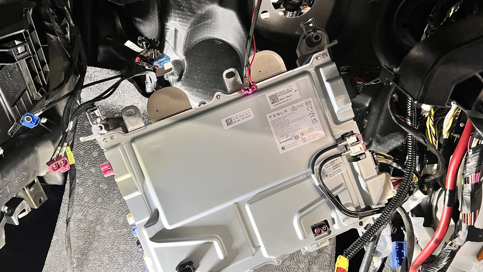
Partially remove car computer to
access RH connectors
注Avoid straining harness
-
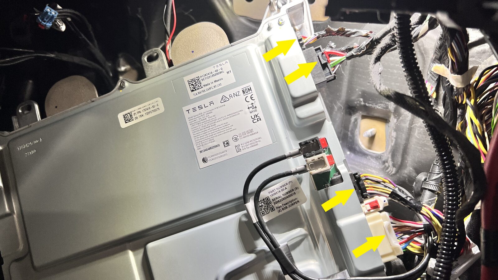
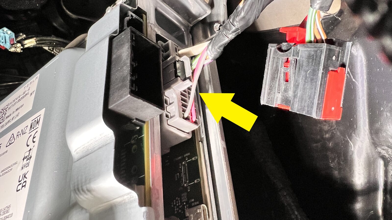
Release connectors at RH side of car
computer
注5x connectors, Release locks on connectors if equipped before removal
-
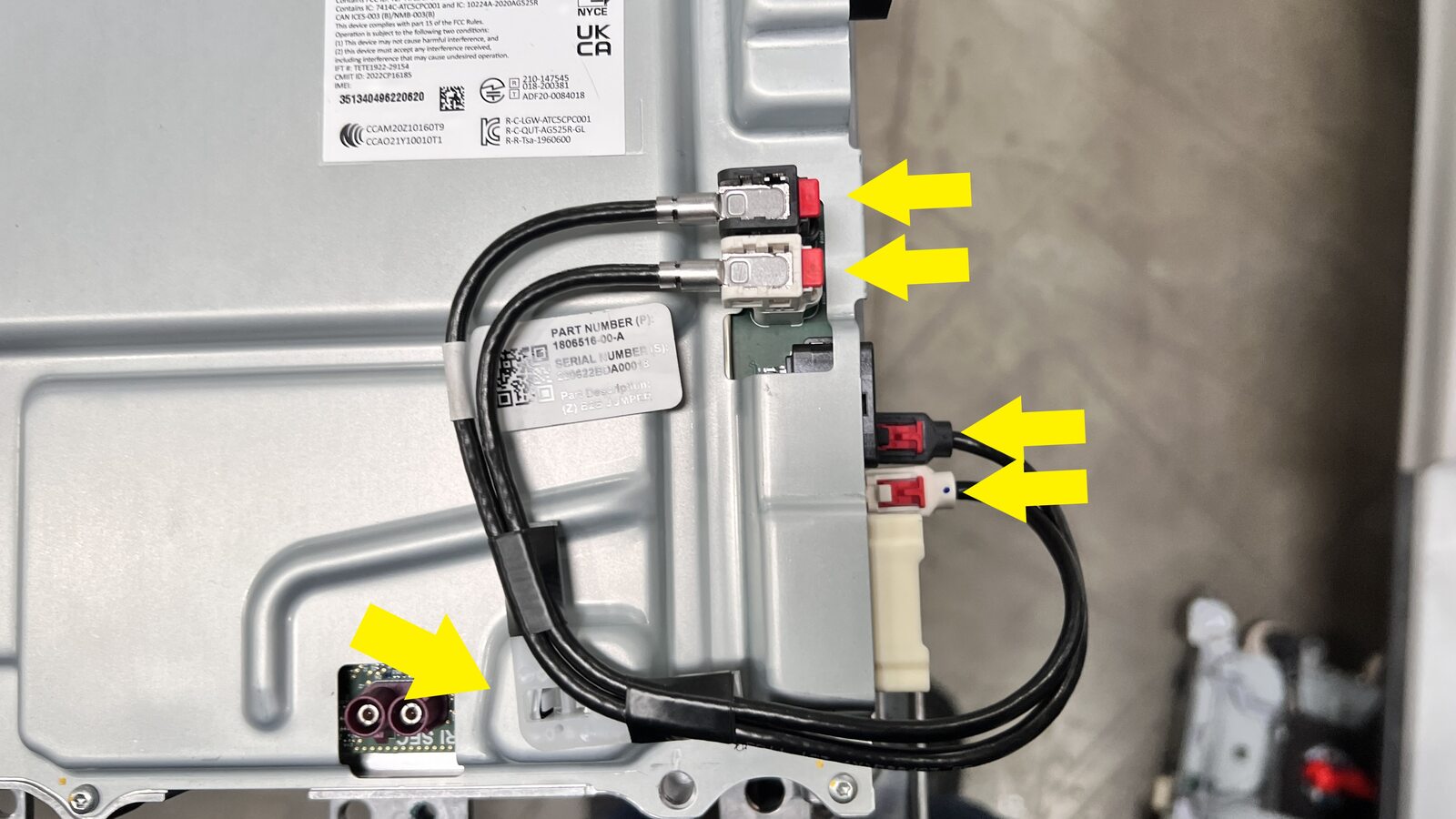
Remove board to board jumper
注4x connectors, 1x harness clip, This will be installed on new car computer


安装
-
Install board to board jumper on the
car computer
注4x connectors, 1x harness clip, Engage locking tabs
-
Secure connectors at RH side of car
computer
注5x connectors, Engage locks on connectors if equipped
-
Install car computer to mounting
studs
注2x nuts, 13mm, 8 Nm
-
Install connectors on front side of
car computer
注2x connectors
-
Install connectors at LH side of car
computer
注5x connectors, Engage locking tabs if equipped
-
Secure ground strap to car
computer
注1x bolt, T25, 4 Nm, Bolt located, Install new bolt
-
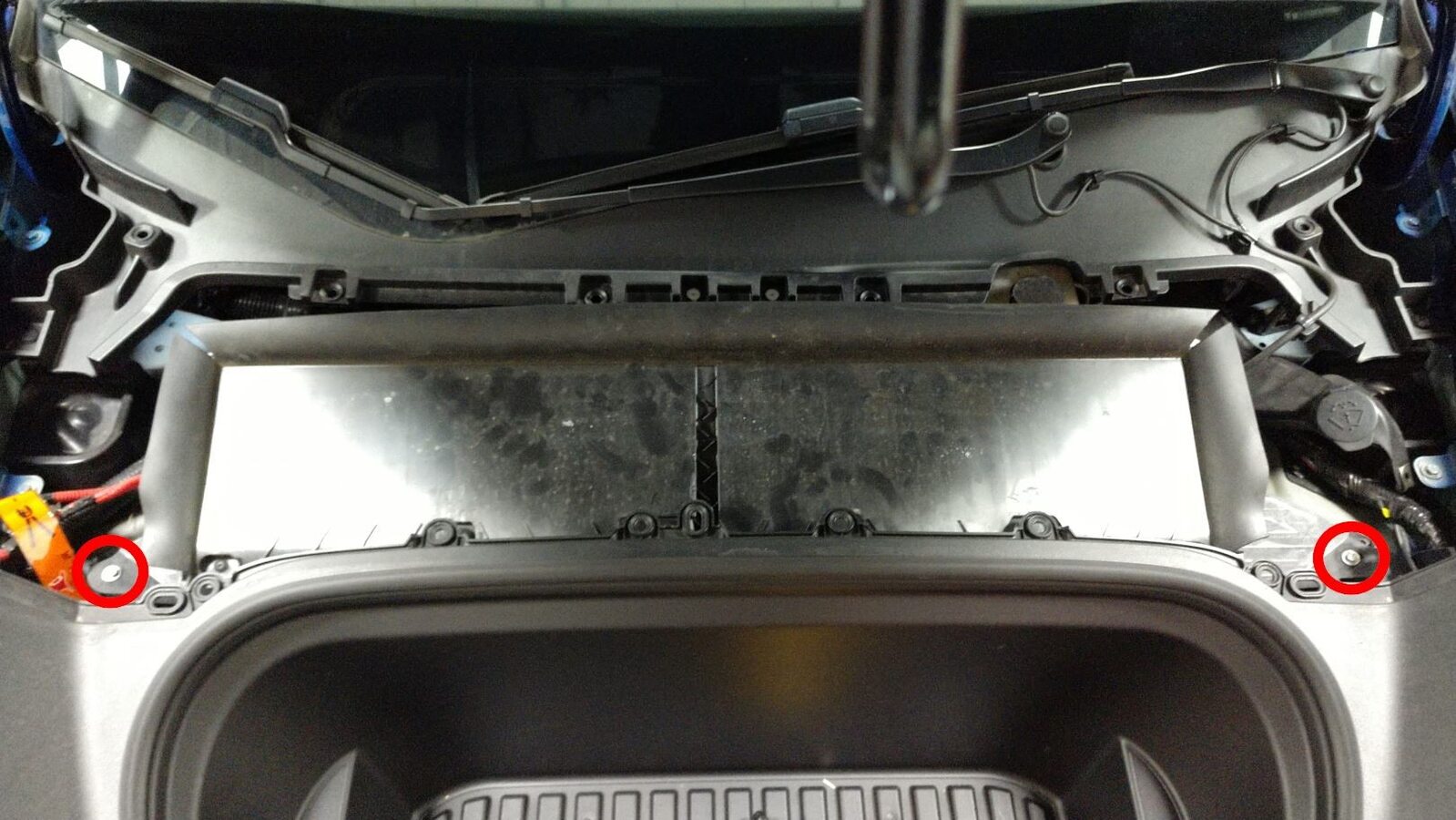
Install the bolts (x2) that attach the car computer to the bulkhead.
注13 mm, 15 Nm
-
Remove plugs from car computer coolant
hoses
注2x plugs, Engage spring clips after removal
-
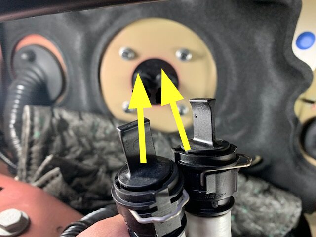
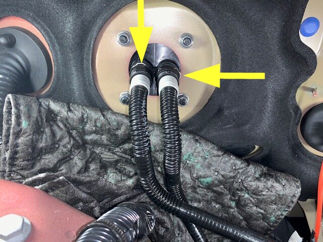
Secure hoses to car computer coolant
inlet/outlet
注2x spring clips, Perform push-pull-push test to ensure the hoses are fully seated
-
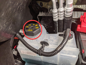
Remove coolant bottle cap
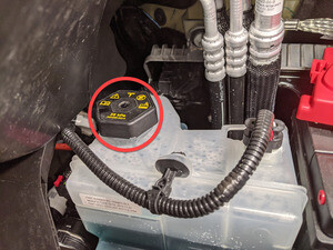
-
Fill coolant bottle to base of neck as
indicated
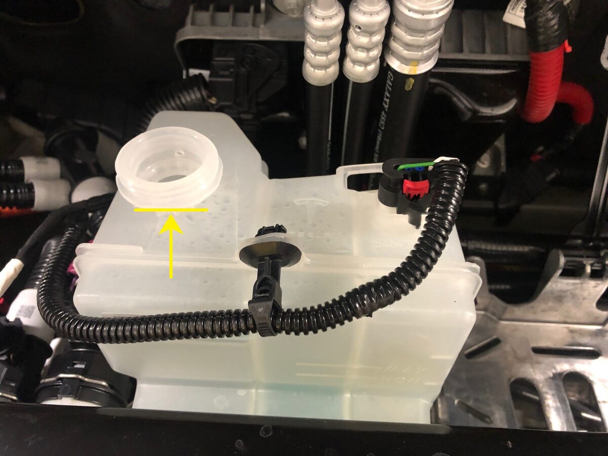
-
Remove absorbent material from below
car computer coolant hose connection points
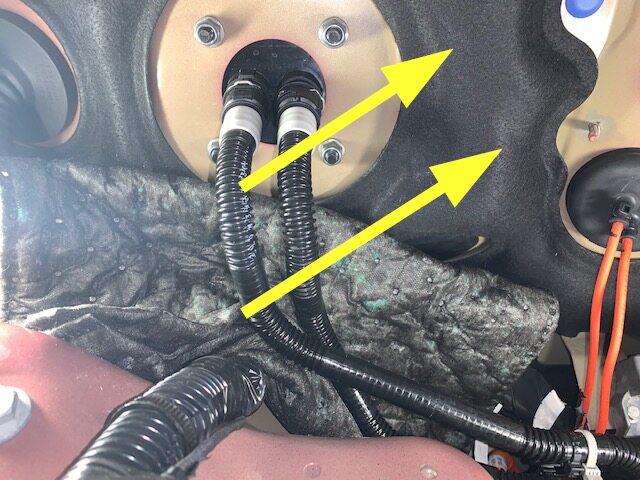
-
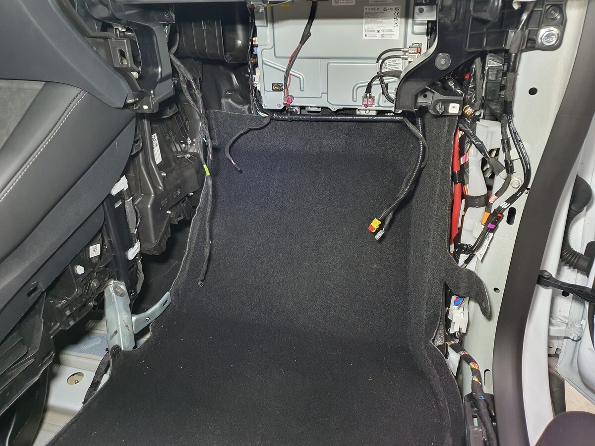
Fold RH main carpet back in
place
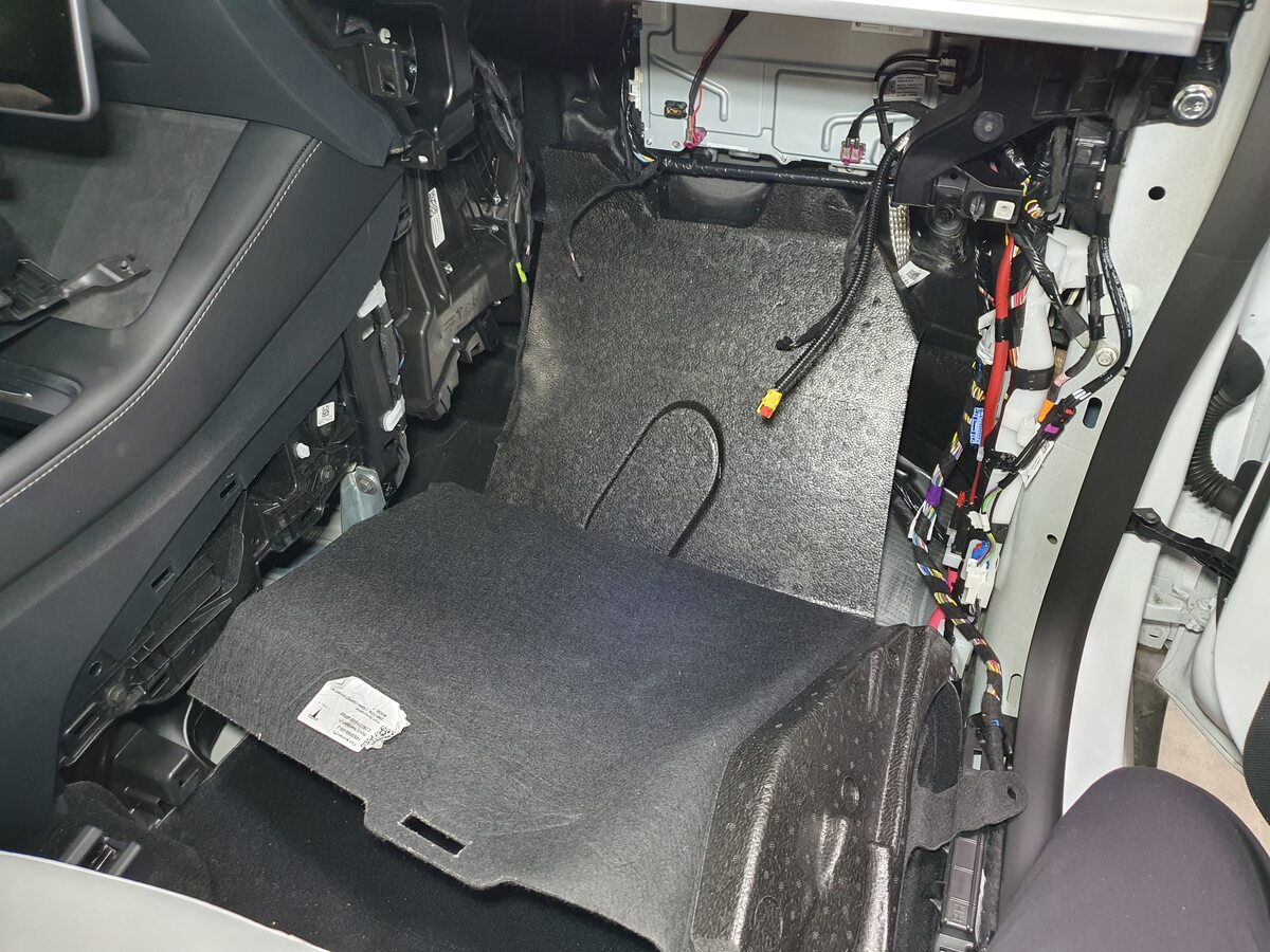
-
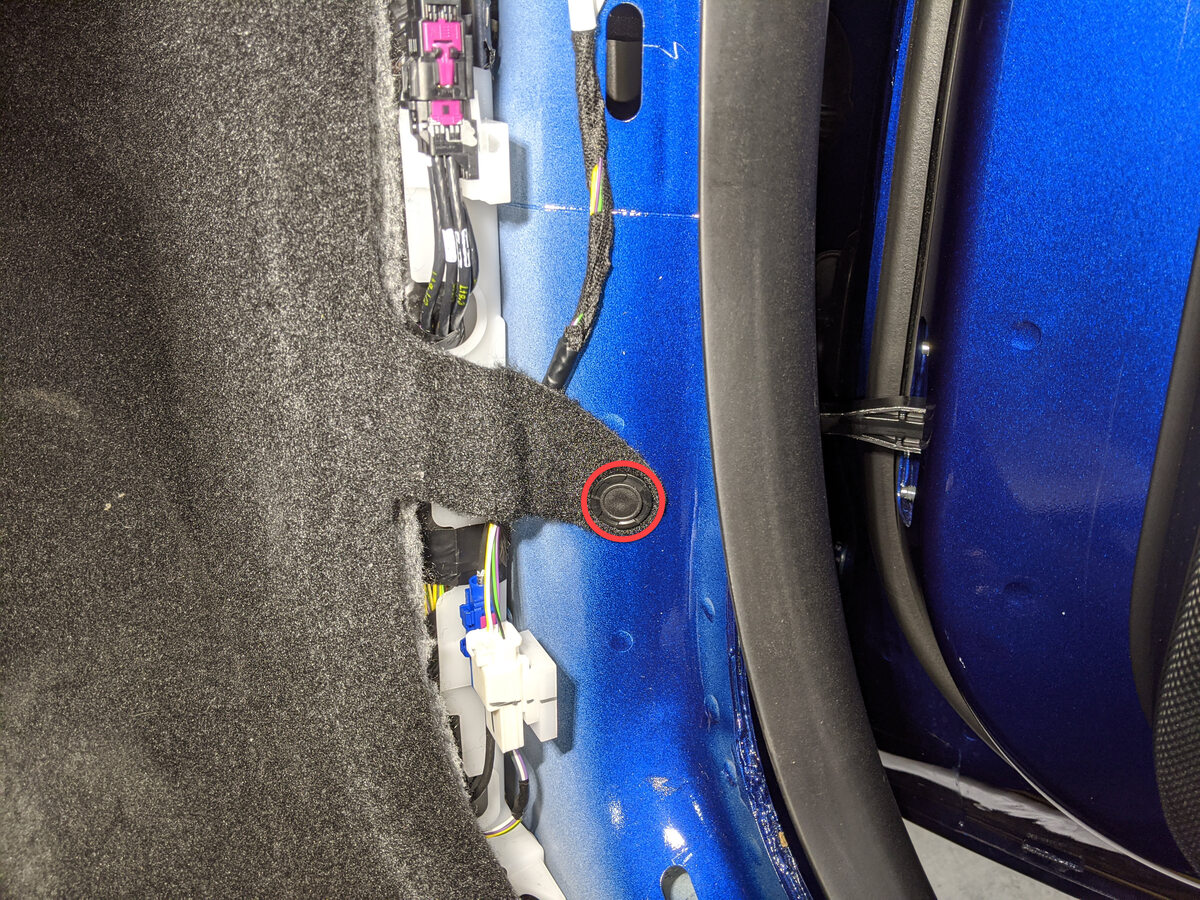
Install clip securing RH front cabin
carpet to body
注1x clip
-
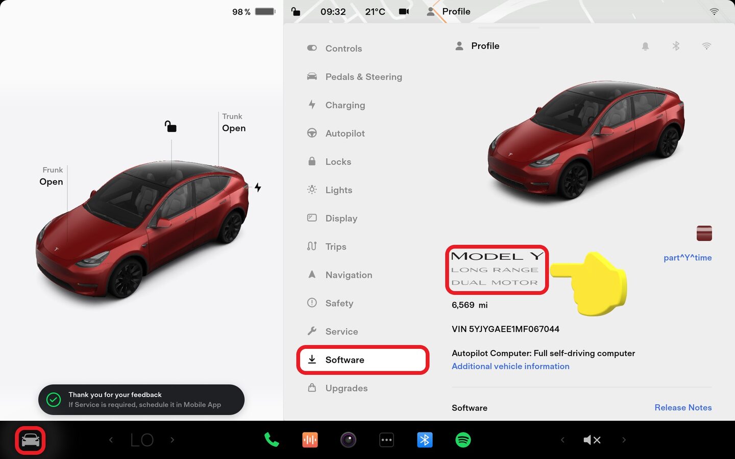
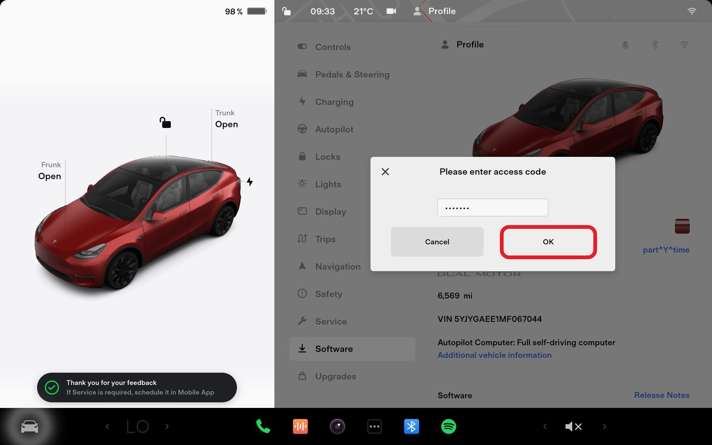
Place vehicle in service mode through
UI
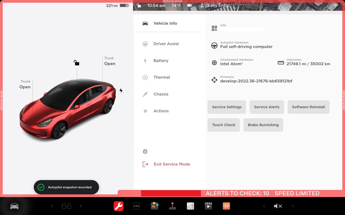
注Select vehicle's badge icon in Controls > Software for four seconds and then type "service" into dialog box And then touch "OK"At last Select ‘X’ at top left of window to close once complete
-
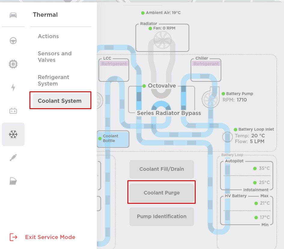
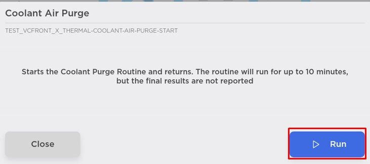
Select "Start Coolant Air Purge" using
the UI
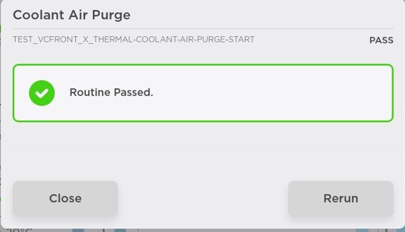
注Touch time only, wait until coolant pumps stop running (audible noise), Routine Passed will appear, but pumps will run for 10 minutes, If you start next another routine during this time, it will fail, Make sure vehicle is not in "Drive", Routine is still running despite the completed message, Speeds can be monitored in garage under PT Thermal tab, Idle speed = ~1500 RPM, Test will vary speeds from 3500-6500 RPM and actuate valves between SERIES and PARALLEL, Putting vehicle into "Drive" will stop this routine, If speeds hover at 7000 RPM, this indicates the pumps are air locked, perform a vacuum fill, Continue to add coolant and purge until the coolant level reaches between the NOM and MAX Lines on the bottle
-
Install coolant bottle cap
-
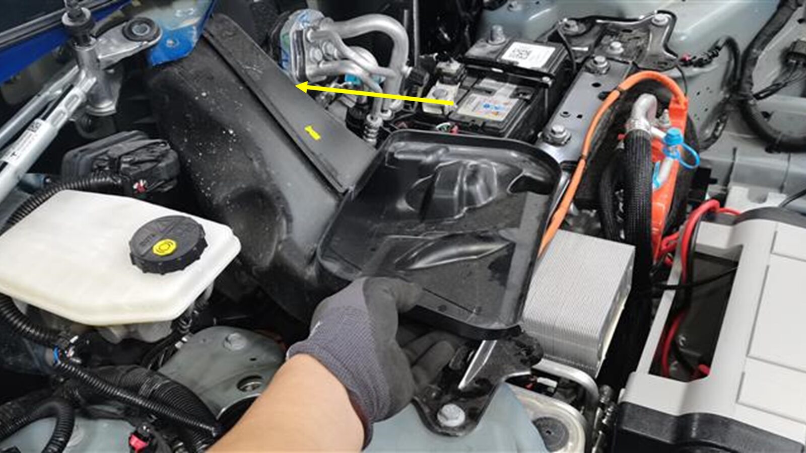
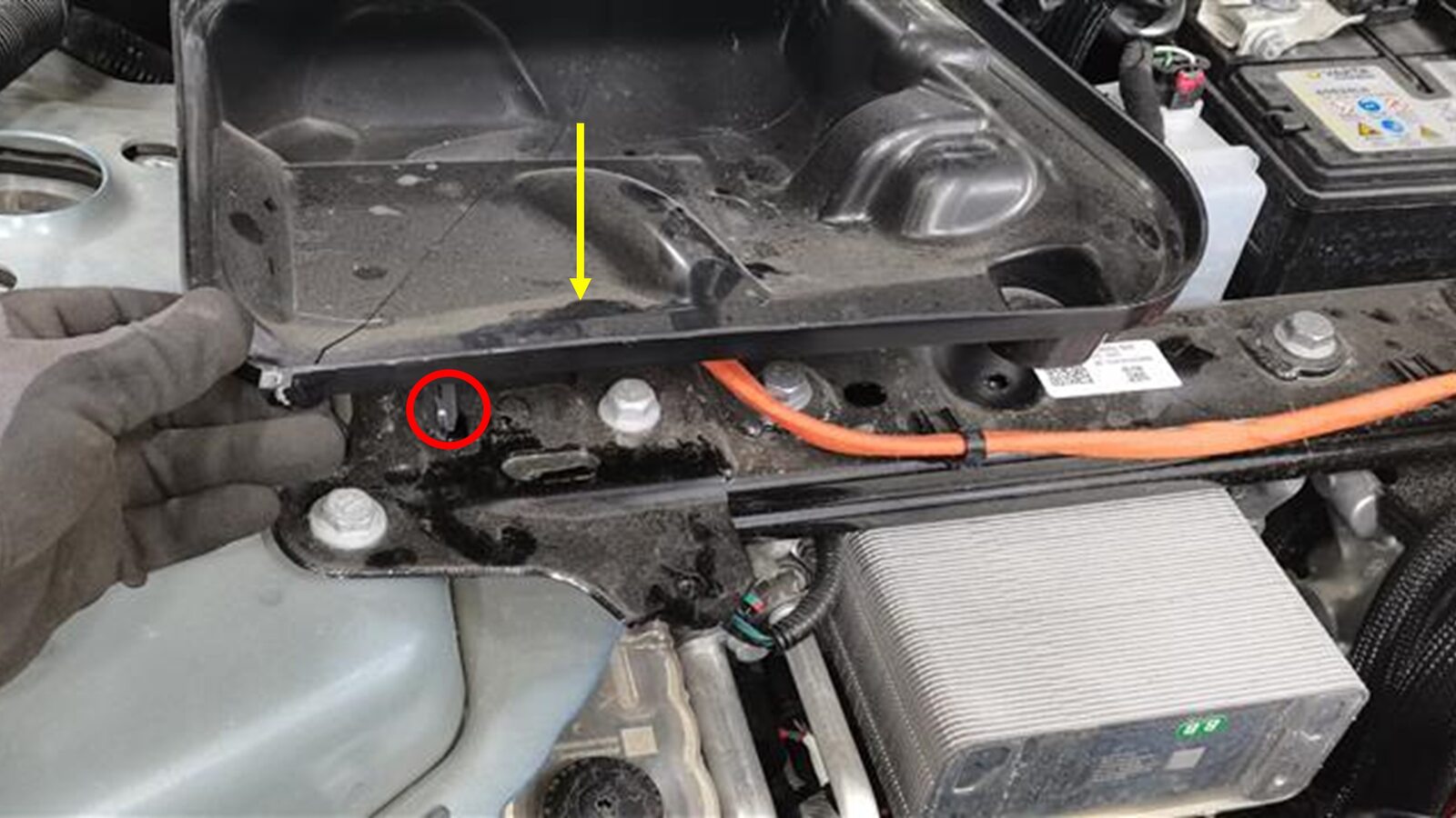
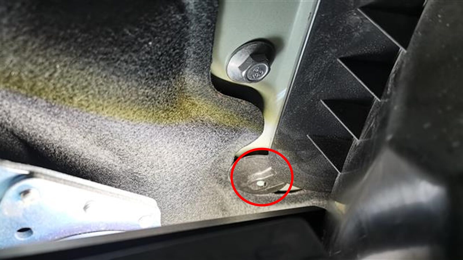
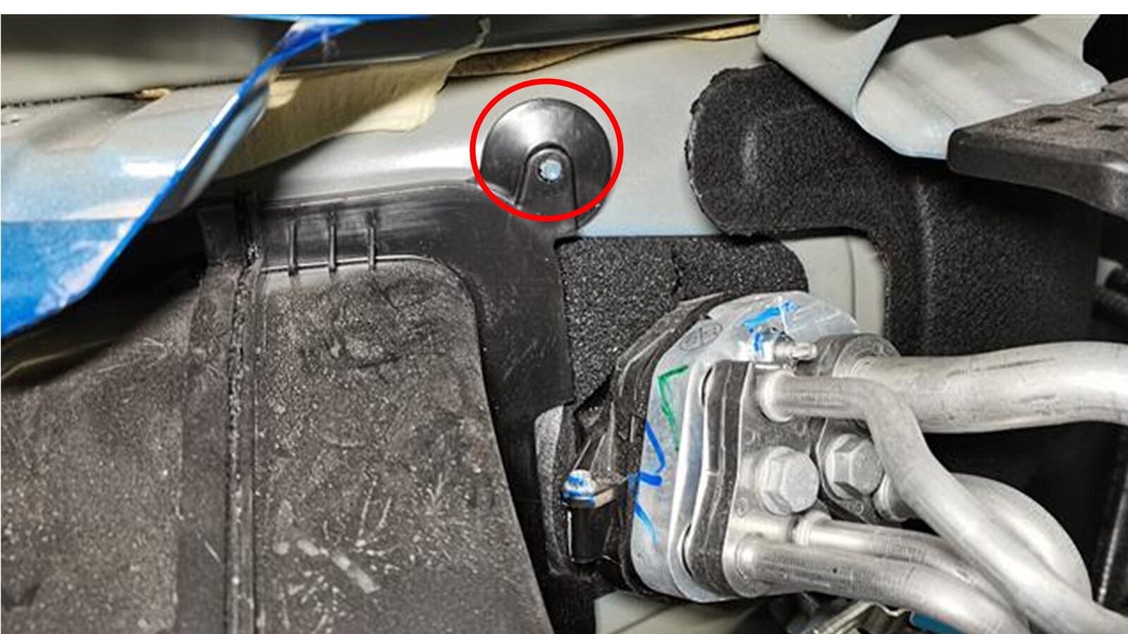
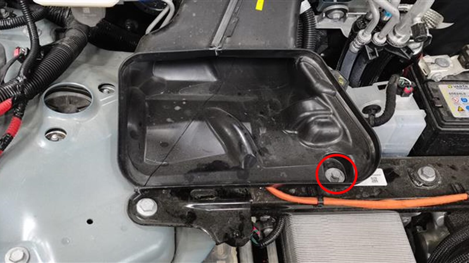
Install fresh air intake duct
注1x bolt, 10mm bolt, 4 Nm, 2x clips, 1x pin, Set clips on bulkhead studs, Secure to thermal bar
-
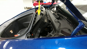
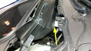
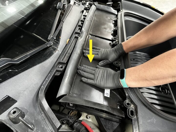
Install HEPA filter assembly
注2x bolts, 10mm, 5 Nm, Pivot forward edge down past frunk assembly, Then carefully move rear edge past brake reservoir and into position, Gently press on RH side of filter to seat seal onto duct, Rework requires new bolts
-
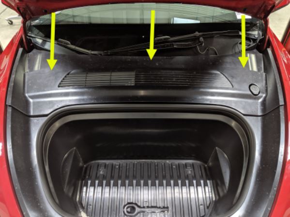
Install the rear apron.
- Close the hood.
-
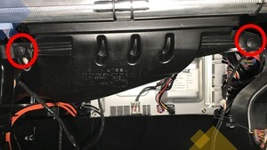
Install the RH IP air wave duct
注2x push clips
-
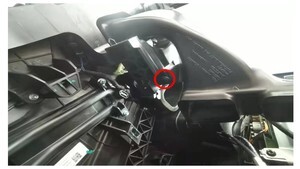
Install the passenger footwell air
duct
注1x push clip
-
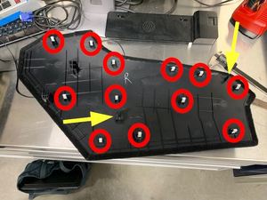
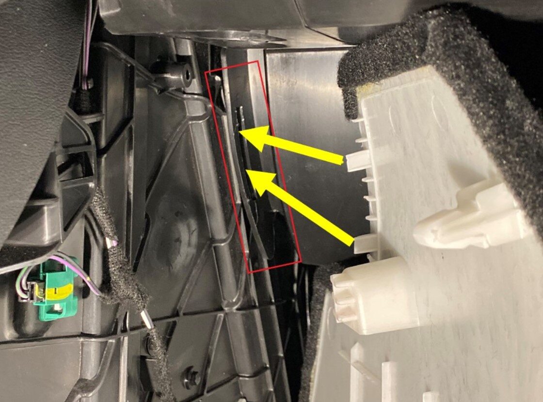
Install RH console side panel
carpet
注12x clips, 2x locating pins, Position side panel and align the front locator, then the rear locator, Push side panel towards console to install
-
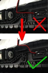
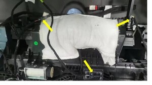
Connect glove box assembly
connectors
注3x connectors, Puddle lamp harness routing prevent blocking movement of pawls
-
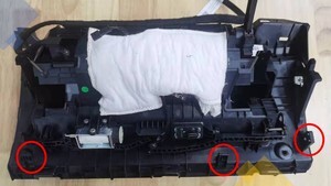
Install glove box into IP
carrier
注3x clips
-
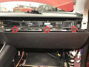
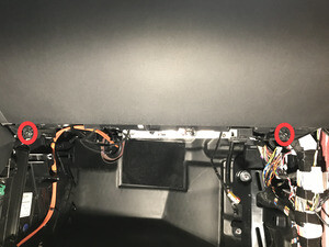
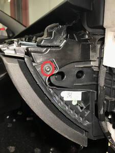
Install screws securing glove box
assembly to IP carrier
注6x screws, T20, 2.3 Nm
-
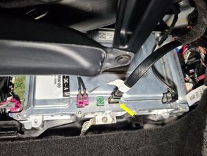
Connect glove box USB cable to car
computer
注1x connector, Connector count may vary depending from config
-
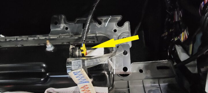
Install passenger knee air bag
注1x connector, Engage locking tab, Use caution not to damage connector/harness, Support air bag while connecting connector
-
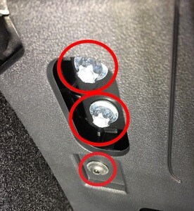
Install fasteners securing passenger
knee air bag to vehicle
注4x patch bolts, E10, 8 Nm, 2x screws, T20, 2 Nm, 1x push clip, Install new patch bolts

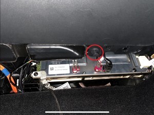
-
Position RH footwell assembly
注2x connectors
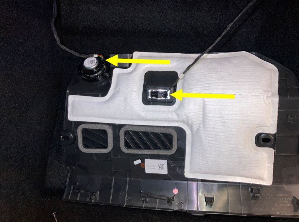
-
Secure RH footwell assembly onto
IP
注1x screw, T20, 1.2 Nm, 1x push clip, 8x tabs, carefully align tabs and push to secure in place
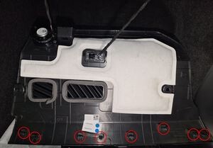
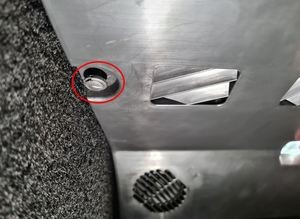
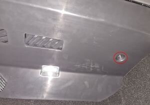
-
Install main decor assembly
注2x screws, T20, 2.3 Nm, 15x clips, 1x center clip, Replace securing clips as needed
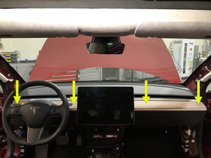
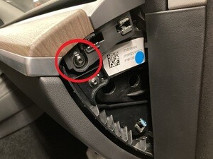
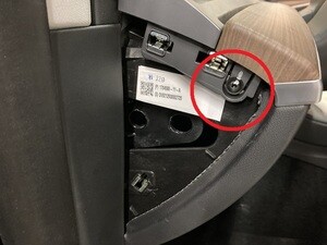
-
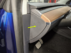
Install LH IP end cap
注3x clips
-
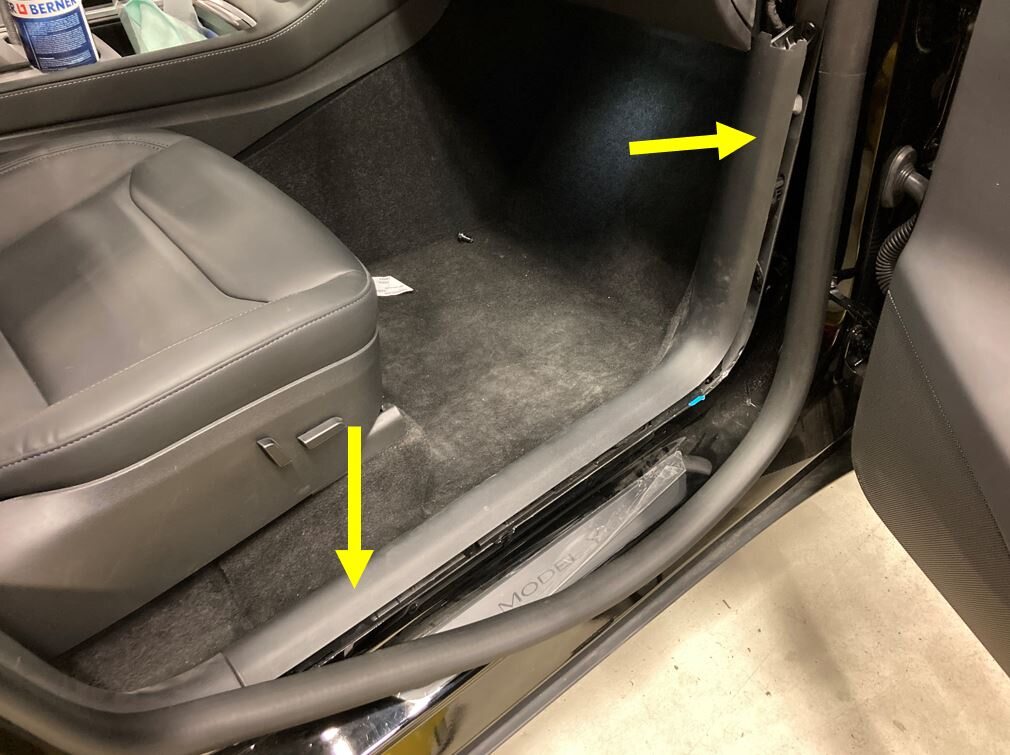
Install RH lower A-pillar trim
注6x clips, 2x locating pins, Align front locating pin first
-
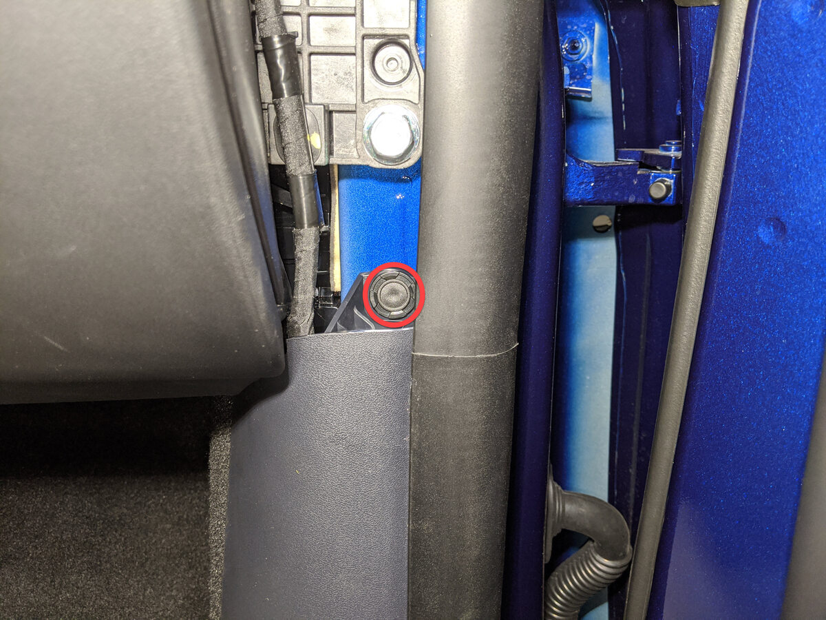
Install clip securing RH lower
A-pillar trim
注1x clip
-
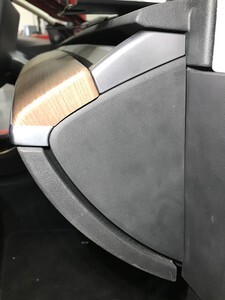
Install RH IP end cap
注3x clips
-
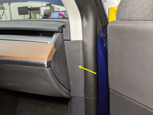
Install RH mid A-pillar assembly
注1x clip, 1x tab, Align the bottom tab then push the top clip to fully seat mid A-pillar, Make sure the seal seat on top of the trim
-
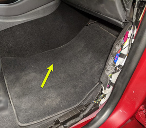
Install RH front floor mat
- Move the RH front seat to its original position.
-
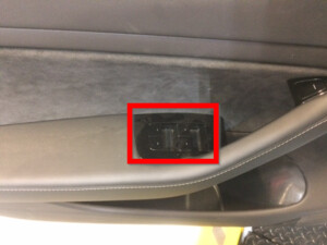
Raise all four windows
-
Close all four doors
注If 12V is powered up, Unlatch rear doors before closing