17/06/2024 21:24:07
分流器 - 高压电池(结构化电池组)(拆卸和更换)
 校正代码
16303632 2.46 注意:除非本程序中另有明确规定,否则上述校正代码和 FRT 反映的是执行本程序(包括关联程序)所需的所有工作。除非明确要求,否则请勿堆叠校正代码。注意:请参阅平均维修工时,深入了解 FRT 及其创建方式。要提供有关 FRT 值的反馈,请发送电子邮件至LaborTimeFeedback@tesla.com。注意:请参阅人员保护,确保在执行以下程序时穿戴适当的个人防护装备 (PPE)。
校正代码
16303632 2.46 注意:除非本程序中另有明确规定,否则上述校正代码和 FRT 反映的是执行本程序(包括关联程序)所需的所有工作。除非明确要求,否则请勿堆叠校正代码。注意:请参阅平均维修工时,深入了解 FRT 及其创建方式。要提供有关 FRT 值的反馈,请发送电子邮件至LaborTimeFeedback@tesla.com。注意:请参阅人员保护,确保在执行以下程序时穿戴适当的个人防护装备 (PPE)。
警告
尽管此程序已经过验证,但仍是一个草案。可能没有警告和注意事项。请遵守安全要求,处理或靠近高压系统和部件时,请谨慎操作。请将校正修理内容及反馈发送至ServiceDevelopment@teslamotors.com。
- Open all four doors
- Lower all four windows
-
Place vehicle in service mode with touchscreen
注Hold Tesla T icon at top of center display for four seconds and then type "service" into dialog box
- Remove the ancillary bay cover. See 盖板 - 高压电池仓(结构化电池组)(拆卸和更换).
- 拆下烟火电池隔离开关。请参阅烟火电池断接开关(结构化电池组)(拆卸和安装)。
-
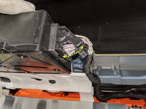
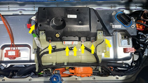
Disconnect HV controller connectors
注7x connectors, Lift hinge upwards to release levered connection
-
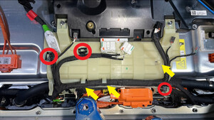
Release harness clips from HVC hinge tray and route harness away
注3x clips
-
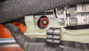
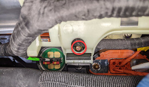
Remove bolts securing HV controller hinge tray to HV battery
注2x bolts, 8mm, 2 Nm
-
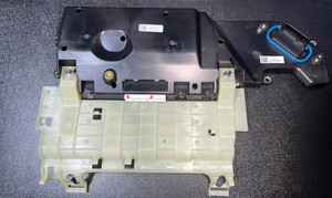
Remove HV controller and tray from ancillary bay
-
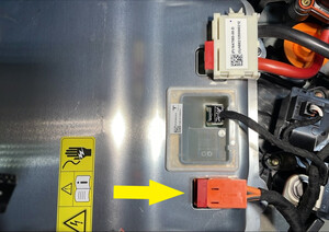
Disconnect PCS to DC bus HV connector
注1x connector, Release the locking tab by pulling upward, May need plastic trim tool to help lift the connector upward
-
Disconnect PCS logic connector from PCS
注1x connector
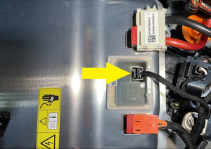
-
Disconnect PCS LV connector from PCS
注1x connector, Release the locking tab by pulling upward, May need plastic trim tool to help lift the connector upward
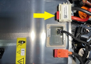
-
Remove bolts securing PCS to HV battery
注6x bolts, 8mm, 6 Nm, Ensure ONLY the 8mm fasteners are removed, Do not remove the T30 fasteners
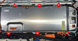
-
Disconnect shunt assembly
注1x connector
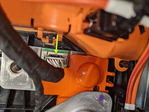
-
Disconnect fast charge contactor
注1x connector, Push on both side of connector to release tabs and pull upward
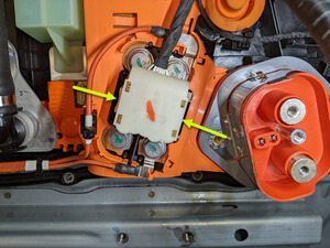
-
Release shunt harness branch from tray
注1x clip
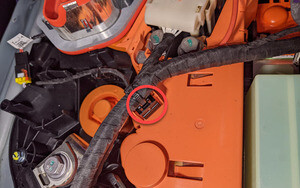
-
Remove bolt securing AC filter harness to negative DC inlet busbar
注1x bolt, 13mm, 15 Nm, Minus 180 degrees, 5 Nm + 60 degrees, Discard after removal
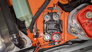
-
Remove bolt securing AC filter harness positive DC inlet busbar
注1x bolt, 13mm, 15 Nm, Minus 180 degrees, 5 Nm + 60 degrees, Discard after removal
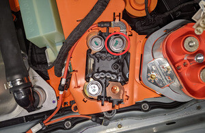
-
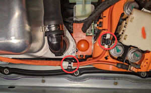
Release AC filter harness from tray
注2x clips
-
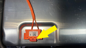
Disconnect AC filter harness
注1x connector, Release the locking tab by pulling upward, May need plastic trim tool to help lift the connector upward
-
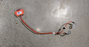
Remove AC filter harness from ancillary bay
-
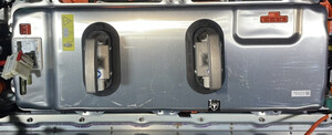
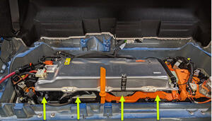
Lift front side of PCS and support
注Recommend assistance, Be cautious of coolant hoses and surrounding components. Use air bladder and plastic tool or similar to keep PCS upright
-
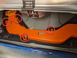
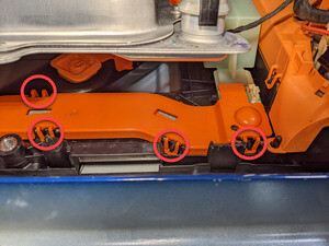
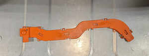
Remove flex jumper busbar insulator
注8x securing tabs, Be very gentle when releasing these tabs as they are very brittle, If damage occurs, replace insulator
-
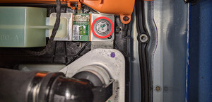
Remove bolt securing shunt assembly
注1x bolt, 13mm, 5 Nm + 60 degrees, Discard bolt after removal
-
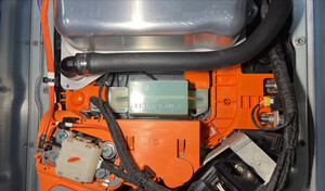
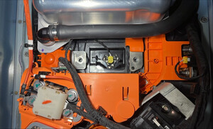
Remove pyro disconnect dummy cover
-
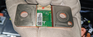
Remove shunt assembly from ancillary bay
注Use trim tool to lift one side to ease removal

-
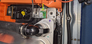
Position shunt assembly into ancillary bay
-
Install pyro disconnect dummy cover
-
Install bolt securing shunt assembly
注1x bolt, 13mm, 5 Nm + 60 degrees, Install new bolt
-
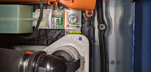
Perform Hioki measurement at joint from shunt to shunt pyro jumper busbar
注1x HV joint, 60µΩ or less
-
Install flex jumper busbar insulator
注8x securing tabs, If damage is present, replace insulator
-
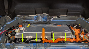
Lower front side of PCS back into position for installation
注Remove tooling supporting PCS
-
Install bolts securing PCS to HV battery
注6x bolts, 8mm, 6 Nm
-
Connect PCS to DC bus HV connector
注1x connector, Secure connector and engage red locking tab, Make sure the connector is fully seated
-
Connect PCS logic connector to PCS
注1x connector
-
Connect PCS LV connector to PCS
注1x connector, Secure connector and enage red locking tab, Make sure the connector is fully seated
-
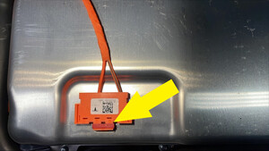
Connect PCS to fastcharge contactor HV harness connector
注1x connector, Secure connector and enage red locking tab, Make sure the connector is fully seated
-
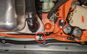
Secure AC filter harness onto tray
注2x clips
-
Install bolt securing AC filter harness positive DC inlet busbar
注1x bolt, 13mm, 15 Nm, Minus 180 degrees, 5 Nm + 60 degrees, Install new bolt
-
Install bolt securing AC filter harness to negative DC inlet busbar
注1x bolt, 13mm, 15 Nm, Minus 180 degrees, 5 Nm + 60 degrees, Install new bolt
-
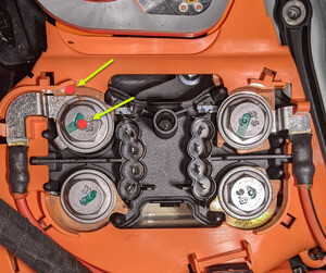
Perform Hioki impedance measurement at joint from AC filter harness to positive DC inlet busbar
注1x HV joint, 150µΩ or less
-
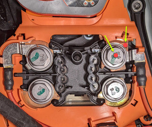
Perform Hioki impedance measurement at joint from AC filter harness to negative DC inlet busbar
注1x HV joint, 150µΩ or less
-
Secure shunt harness branch onto tray
注1x clip
-
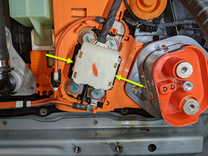
Connect fast charge contactor
注1x connector, Push on both side of connector to release tabs and pull upward
-
Connect shunt assembly
注1x connector
- 测量烟火电池隔离开关安装点间的电压,然后安装烟火电池隔离开关。请参阅烟火电池断接开关(结构化电池组)(拆卸和安装)。
-
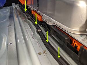
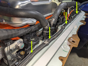
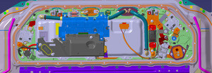
Inspect ancillary bay phantom seal to verify no damage is present
注If damage is present, Replace ancillary bay phantom seal
-
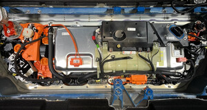
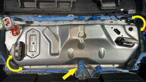
Install ancillary bay cover onto HV battery
注Recommend assistance, Guide LH side in, Maneuver cover past body casting and into position with charge port components
-
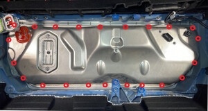
Install perimeter bolts securing ancillary bay to HV battery
注22x captured bolts, EPL 10, 5 Nm, Thread bolts in evenly and torque
-
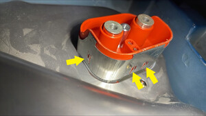
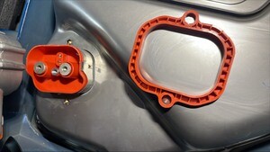
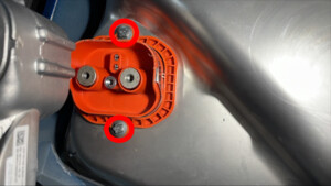
Secure doubler and install fasteners securing charge port header to ancillary bay cover
注2x bolts, 10 EPL, 10 Nm, Secure doubler onto header and install bolts, Take note of small tabs on shielding
-
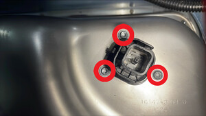
Install fasteners securing PCS LVDC header to ancillary bay cover
注3x bolts, T20, 2.5 Nm
-
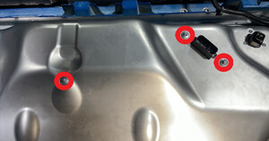
Install fasteners securing ancillary bay cover to high voltage controller
注3x bolts, E10, 10 Nm
-
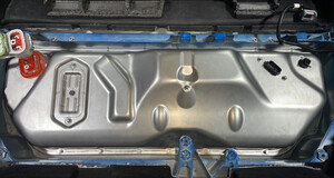
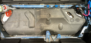
Install NVH insulation onto ancillary bay cover
-
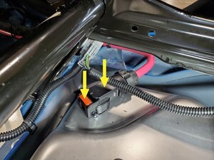
Connect power connector to HV battery
注1x connector, Push red locking tab down to secure connection
-
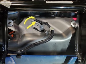
Connect HVC logic connector
注1x connector, Pivot handle upward to engage connector and secure locking tab, Remove cap if needed
-
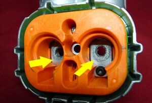
Clean busbar HV connector contact surface of residual Penetrox
注Allow 1 minute dry time after removing Penetrox, It is necessary to clean HV connector during re-use of busbar
-
Clean HV connector contact surface of residual Penetrox
注Allow 1 minute dry time after removing Penetrox, New busbar comes with Penetrox applied to HV connector
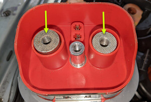
-
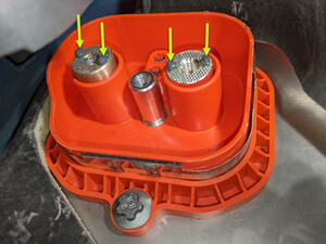
Apply Penetrox onto HV connector joints
注Apply 2 drops of Penetrox A-13 about 5mm in diameter to either side of the hole on both leads, Spread evenly to verify the contact surface is fully covered
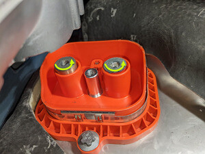
-
Position busbar kit connector and lower onto HV header
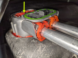
-
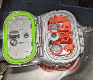
Install bolts securing charge port busbar kit to HV Header
注2x bolts, 10mm, 9 Nm
-
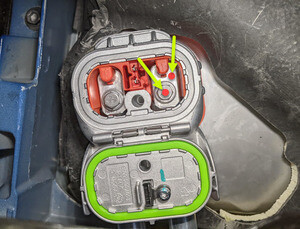
Perform Hioki resistance test at each HV joint from HV busbar lead to bolt head
注2x HV joints, The acceptable resistance is between 0.050 mΩ (50 μΩ) and 0.195 mΩ (195 μΩ).If the resistance is greater than 0.195 mΩ (195 μΩ), there is too much resistance in the High Voltage joint. Remove the fastener, clean areas with isopropyl alcohol, install fastener back and test again.If the resistance is lower than 0.050 mΩ (50 μΩ), reposition the probes and measure again.If the resistance is repeatedly between 0.00 mΩ and 0.050 mΩ (50 μΩ), hioki test passed, proceed to next step
-
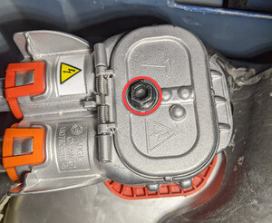
Install fastener securing busbar cover access door
注1x bolt, 10mm, 9 Nm
- Remove HV insulating gloves
-
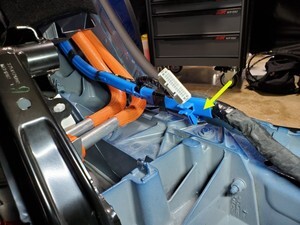
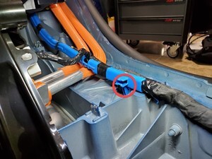
Engage LH body harness onto rear body
注1x clip
-
Raise vehicle fully and lower lift onto locks
注Set vehicle to comfortable working height, Make sure there's an audible click of the locks on both sides before lowering, otherwise vehicle may tilt to the side
-
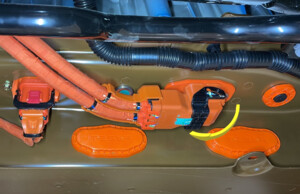
Secure RDU HV harness onto HV battery
注1x connector, Verify lever is in the upright and open position, Carefully seat connector and allow lever to engage, Fully secure lever and verify red tab is locked, Do not damage any pins
-
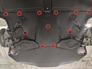
Apply Loctite 222 onto mid aero shield bolts and install mid aero shield
注11x bolts, 10mm, 5 Nm, Fasteners may vary, Model Y Structural Pack will one less bolt and one extra clip
-
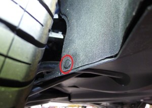
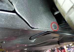
Install push clips at left and right wheel house liner to mid aero shield
注2x clips
-
Lower vehicle fully
注Raise lift off locks, then hold lock release lever to keep locks free while vehicle is lowered
-
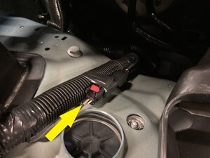
Connect first responder loop and leave LV battery disconnected
注1x connectors, Secure FRL only, Leave LV battery disconnected
-
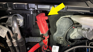
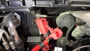
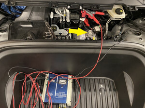
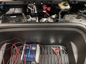
Connect 12V maintainer
注Release positive terminal cover, Connect 12v maintainer to positive terminal and chassis ground, Leave LV battery disconnected
-
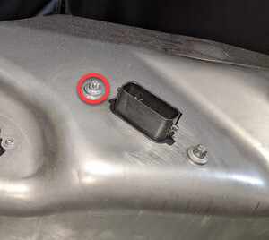
Remove HVC bolt
注1x bolt, E10, 5 Nm + 30 degrees
-
Connect to vehicle using Toolbox 3.0
注Vehicle connection is integrated into drivers footwell cover, Open Toolbox 3 website and establish connection to the vehicle. https://toolbox.teslamotors.com, Select connection status icon at top right corner, and select connect locally (icon will turn green when vehicle is connected)
-
Place holder- Reference hex value from provided document
注Use CTRL + F to search for VIN and then reference the hex value at the right column, Location of document TBD

-
Select ‘Actions/Autodiag’, and search for ‘HVP write shunt ohm'
注https://toolbox.teslamotors.com/dashboards/users?view=sessions&query=repair_network.ODIN_HVP_WRITE_SHUNT_OHM&searchType=actions
-
Select ‘ vehicle environment ’, click ‘Run’, and allow routine to complete
注Continue to follow routine
-
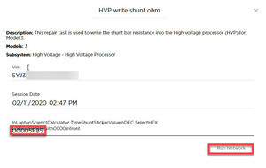
Type shunt resistance in hex format into the pop up window and select "Run Network"
注If value is "0x6229", format to enter is 00006229
- Remove ethernet cable from Ethernet port to disconnect Toolbox 3.0 from vehicle
-
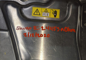
Write shunt resistance value and date onto top of ancillary bay cover for future reference
注Resistance value is also on the spreadsheet or can be converted from Hex to Decimal through Google

-
Install HVC bolt
注1x bolt, E10, 5 Nm + 30 degrees
-
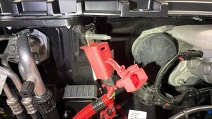
Disconnect 12v maintainer
注Unplug maintainer and release connections from vehicle, Re-secure positive terminal cover

-
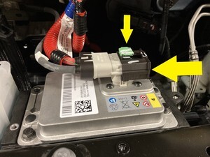
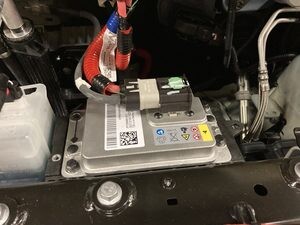
Connect LV battery
注1x connector, Seat LV battery connection and push black connector lock inwards to secure, Engage green locking tab when fully seated
-
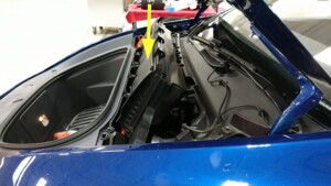
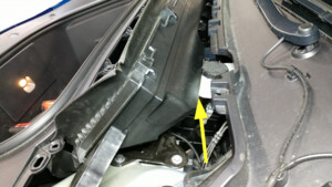
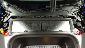
Install HEPA filter assembly
注2x bolts, 10mm, 5 Nm, Pivot forward edge down past frunk assembly, then carefully move rear edge past brake reservoir and into position
-
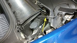
Install washer tank neck to washer tank
注1x O-ring, Ensure washer hose is properly routed after installation
-
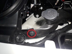
Secure frunk to washer fluid reservoir neck
注1x bolt, 10mm, 5 Nm
- Install the rear underhood apron. See 前备箱挡板 - 后部(拆卸和更换).
- Install the RH 2nd row seat back. See 座椅靠背 - 第二排 - RH(拆卸和更换).
- Install the RH lower c-pillar trim. See 饰板 - C 柱 - 下 - LH(拆卸和更换).
- Install the LH 2nd row seat back. See 座椅靠背 - 第二排 - LH(拆卸和更换).
- Install the LH lower c-pillar trim. See 饰板 - C 柱 - 下 - LH(拆卸和更换).
-
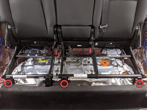
Install clips securing rear main cabin carpet to vehicle
注3x push clips
- Install the 2nd row lower seat cushion. See 座椅座垫 - 下部 - 第二排(拆卸和更换).
- Move LH front seat to original position
- Move RH front seat to original position
-
Exit Service Mode through UI
注Controls > Service Mode > Exit Service Mode
-
Remove vehicle from lift
注Lower rack arms fully and remove from under vehicle
- Raise all four windows
-
Close all four doors
注If 12V is powered up, Unlatch rear doors before closing


