17/06/2024 21:25:03
Assembly - Brake Lines - Master Cylinder to HCU (RHD) ((拆卸和更换))
 校正代码
3303020022
FRT
4.32
注意:除非本程序中另有明确规定,否则上述校正代码和 FRT 反映的是执行本程序(包括关联程序)所需的所有工作。除非明确要求,否则请勿堆叠校正代码。
注意:请参阅平均维修工时,深入了解 FRT 及其创建方式。要提供有关 FRT 值的反馈,请发送电子邮件至LaborTimeFeedback@tesla.com。
注意:请参阅人员保护,确保在执行以下程序时穿戴适当的个人防护装备 (PPE)。
校正代码
3303020022
FRT
4.32
注意:除非本程序中另有明确规定,否则上述校正代码和 FRT 反映的是执行本程序(包括关联程序)所需的所有工作。除非明确要求,否则请勿堆叠校正代码。
注意:请参阅平均维修工时,深入了解 FRT 及其创建方式。要提供有关 FRT 值的反馈,请发送电子邮件至LaborTimeFeedback@tesla.com。
注意:请参阅人员保护,确保在执行以下程序时穿戴适当的个人防护装备 (PPE)。
- 2024-06-17: Added step to perform test drive and add correction code 00040100 as a separate acitivity to the Service Visit.
拆卸
- Remove the steering column. See Steering Rack (Dual Motor) (RHD) ((拆卸和更换)).
- Remove the wiper module. See Wiper Module (RHD) ((拆卸和更换)).
- Remove the fresh air intake assembly. See HVAC,新鲜空气进气口 ((拆卸和更换)).
- Remove the LV battery. See 16V 锂离子电池包 ((拆卸和更换)).
- Remove the shock tower brace. See 减震塔支架总成 ((拆卸和更换)).
- Remove the front controller. See 3 代前控制器总成 ((拆卸和更换)).
-
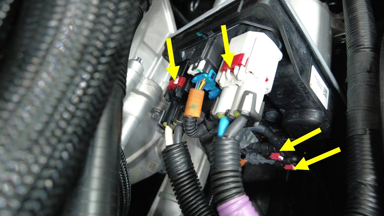
Disconnect the steering gear assembly
connectors (x4).
-
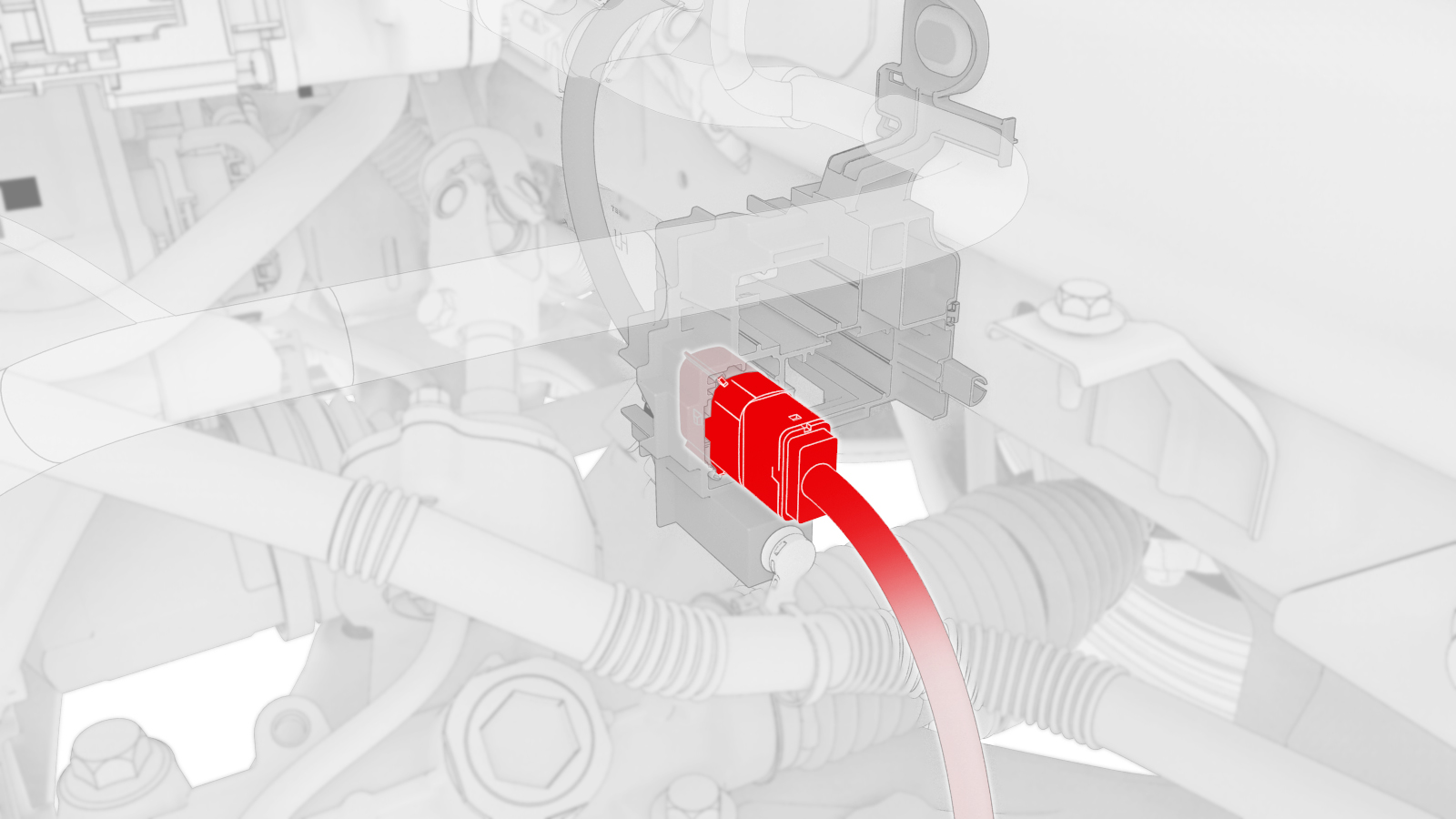
Disconnect FDU front subframe harness
connector.
-
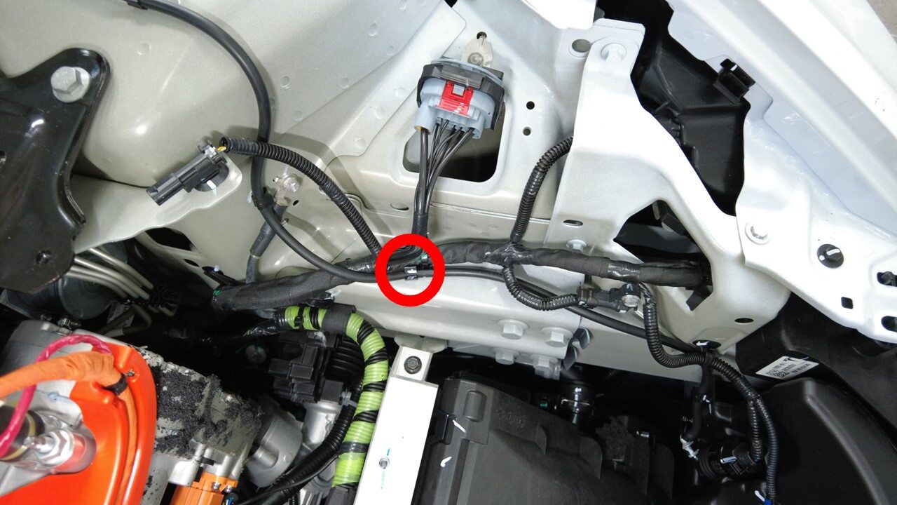
Remove washer hose from LH front frame
rail area
注1x clip
-
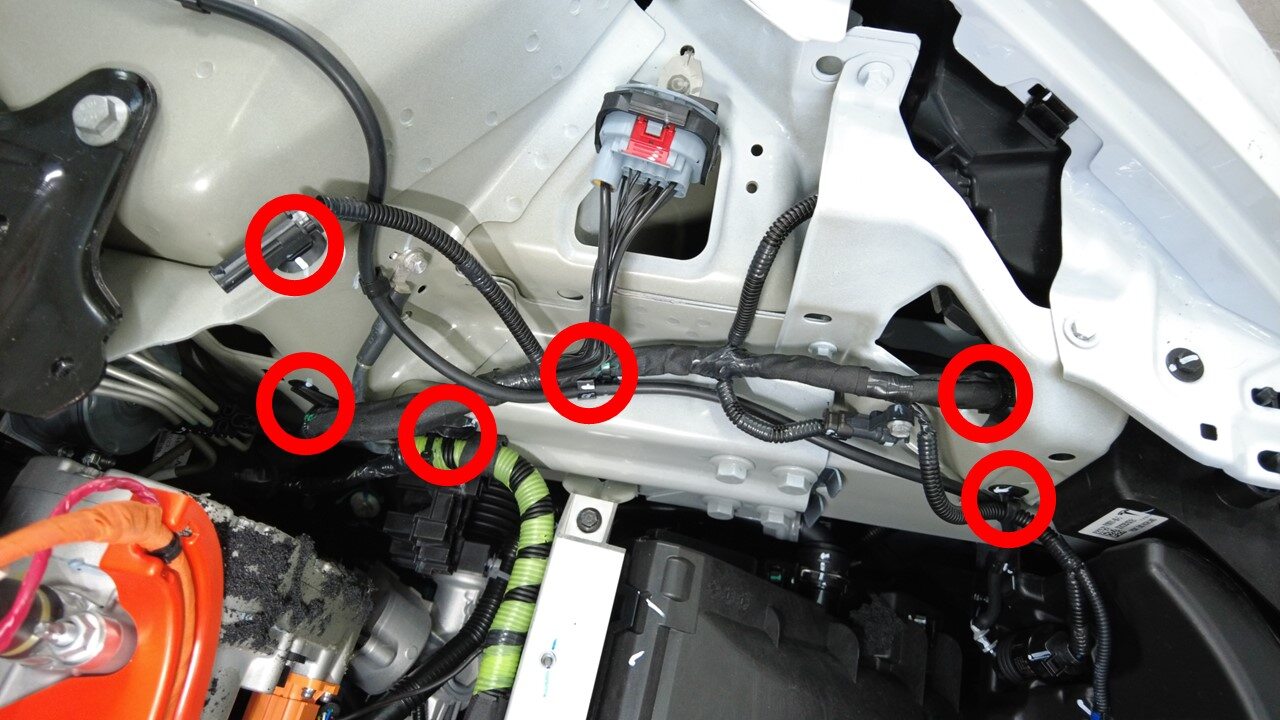
Release front harness clips around LH
front frame rail area
注6x clips
-
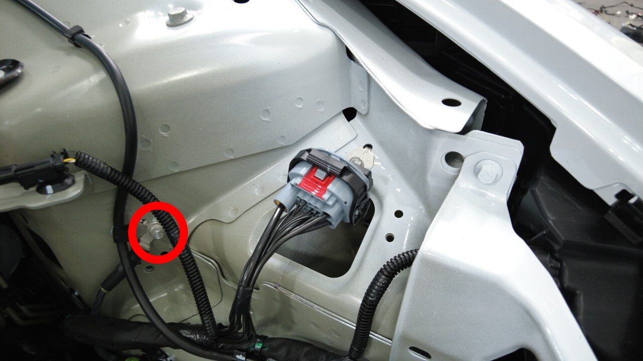
Remove front harness ground terminal
at LH front shock tower
注1x bolts, 10mm, 8 Nm, Inspect bolts: if they are self tapping tri-lobular bolts (1128269-00-A) then discard, If they are normal bolts (1447438-00-A) they can be reused
-
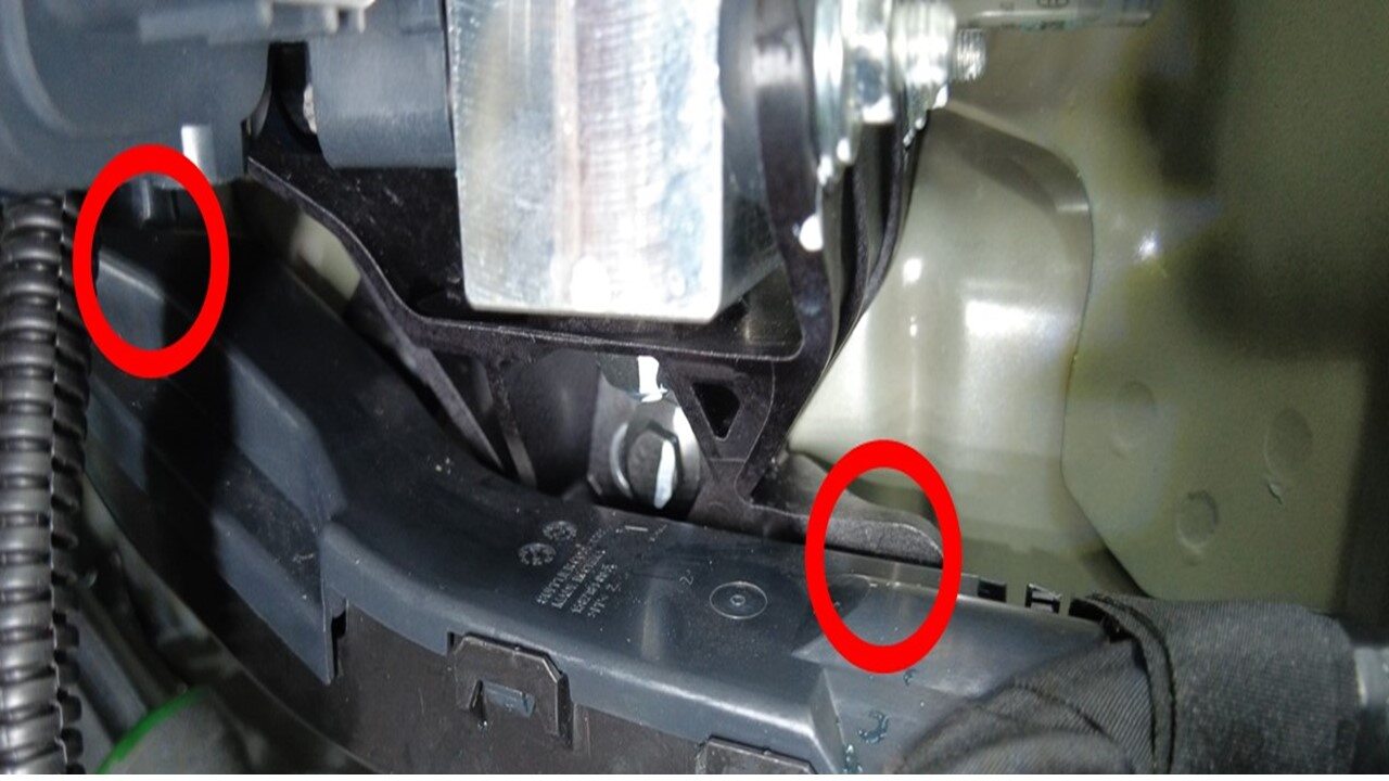
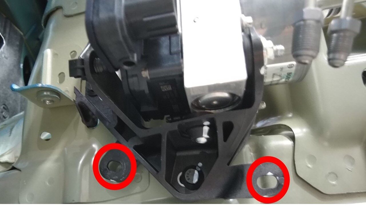
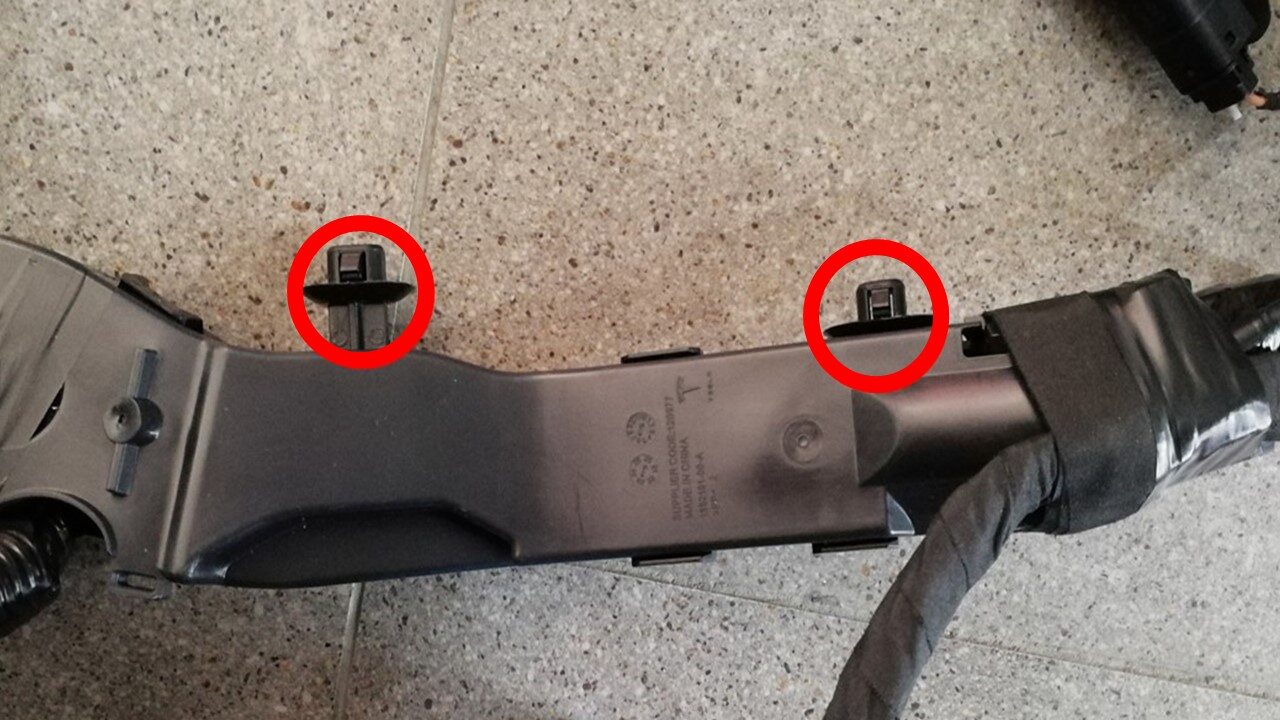
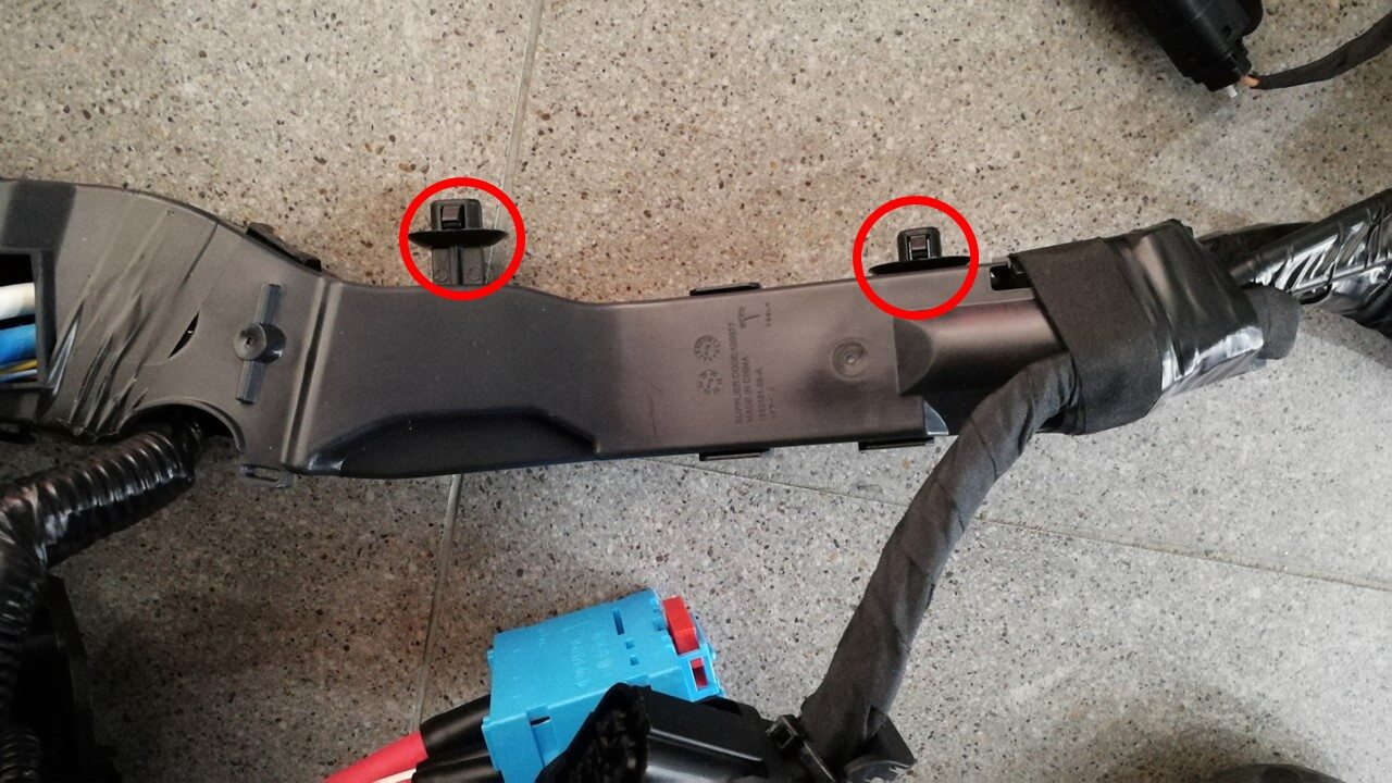
Remove LH harness bracke clip and
remove from vehicle
注2x clips
-
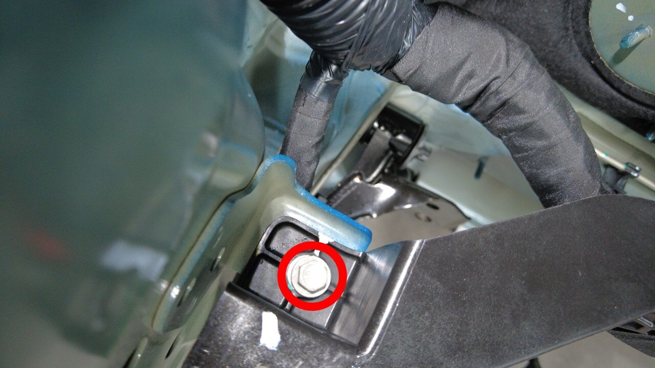
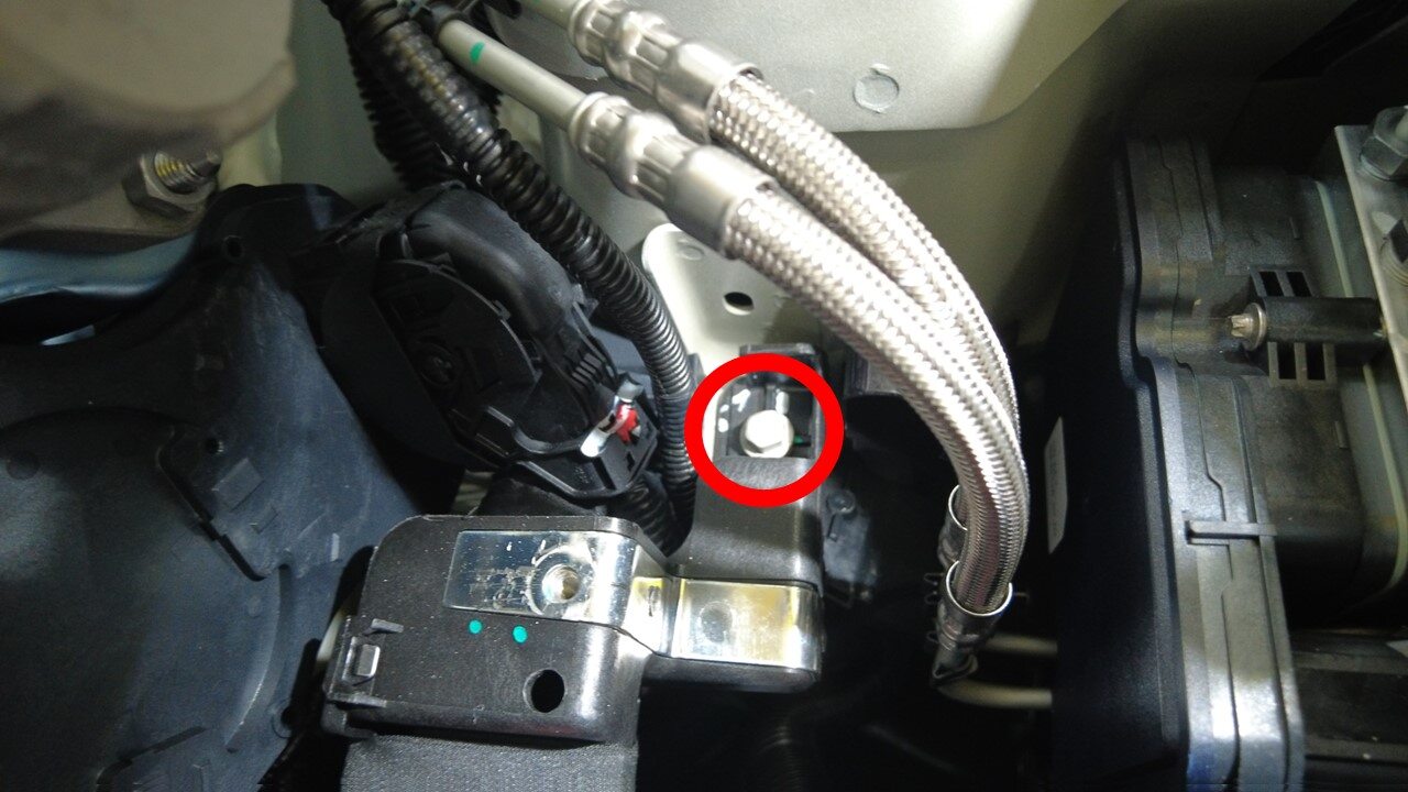
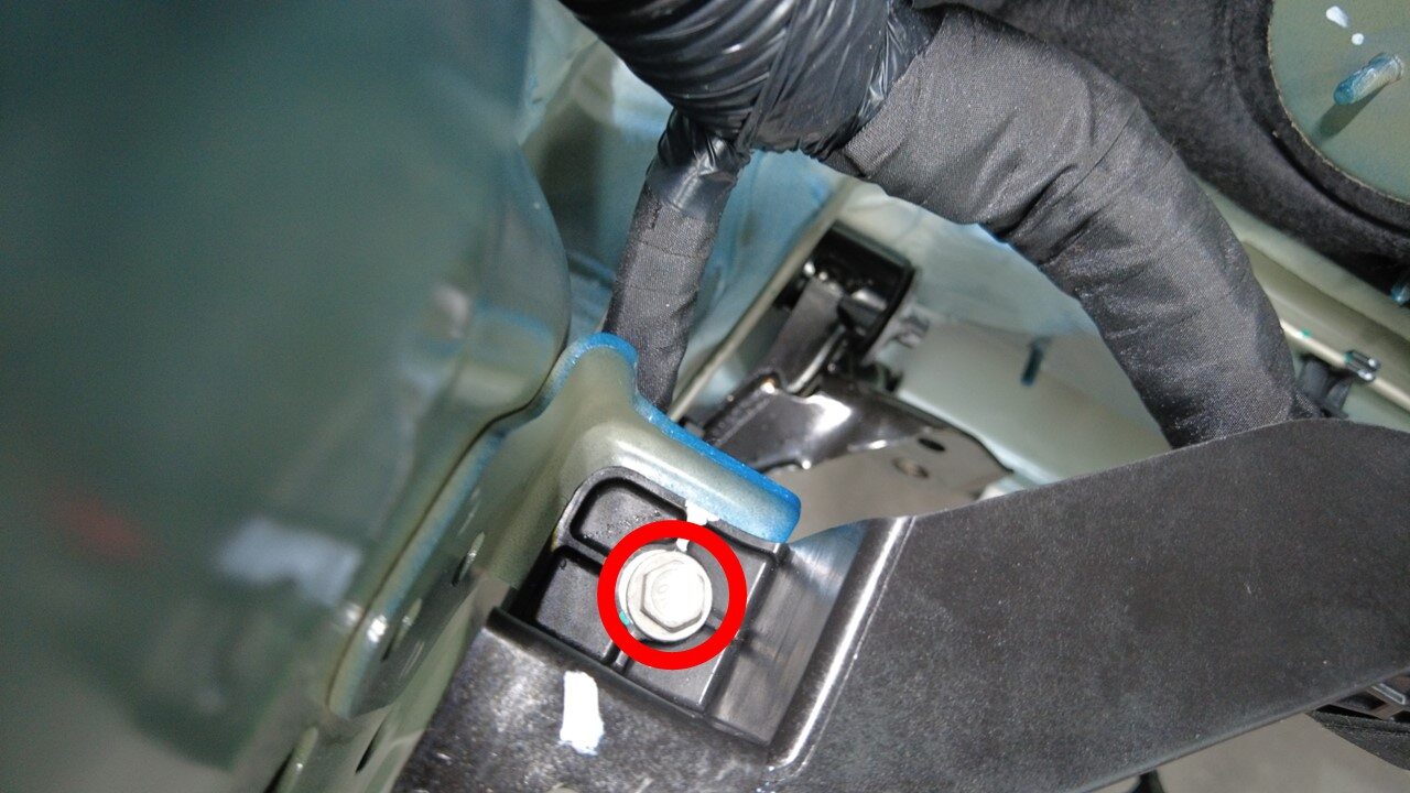
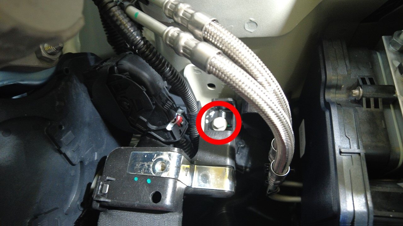
Remove bolts securing front harness
bracke from vehicle
注2x bolts,10mm,9 Nm
-
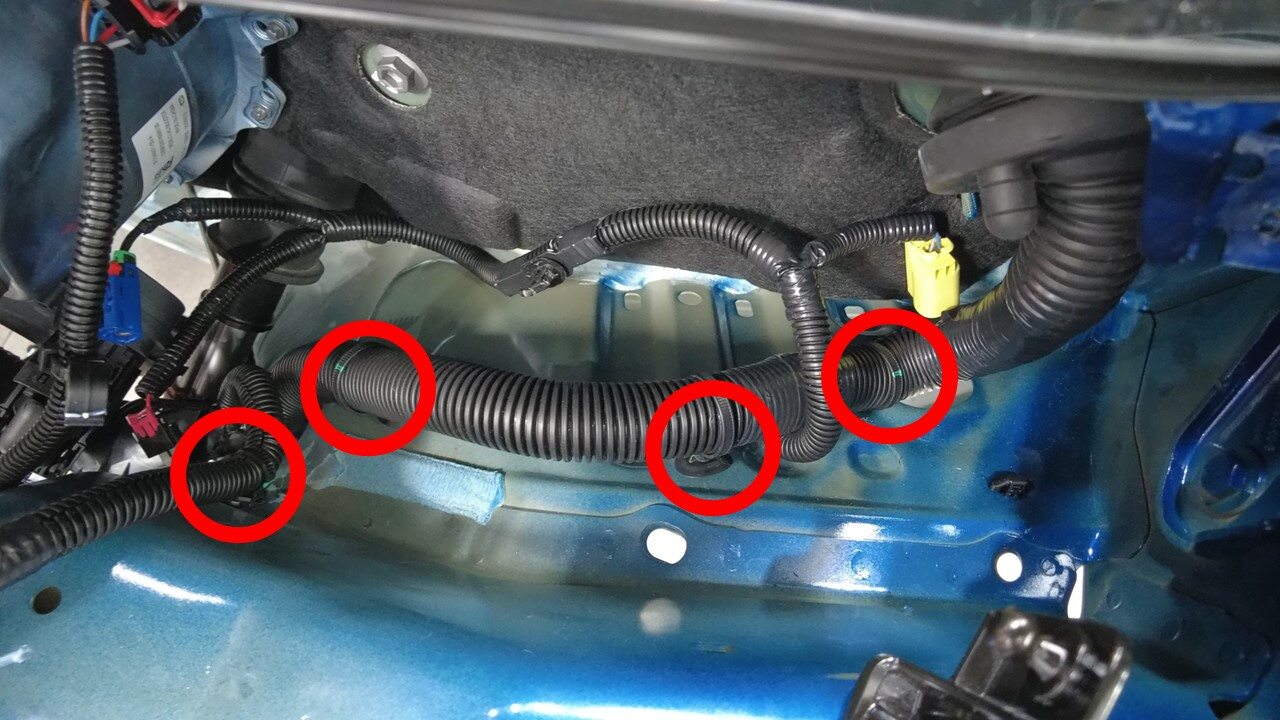
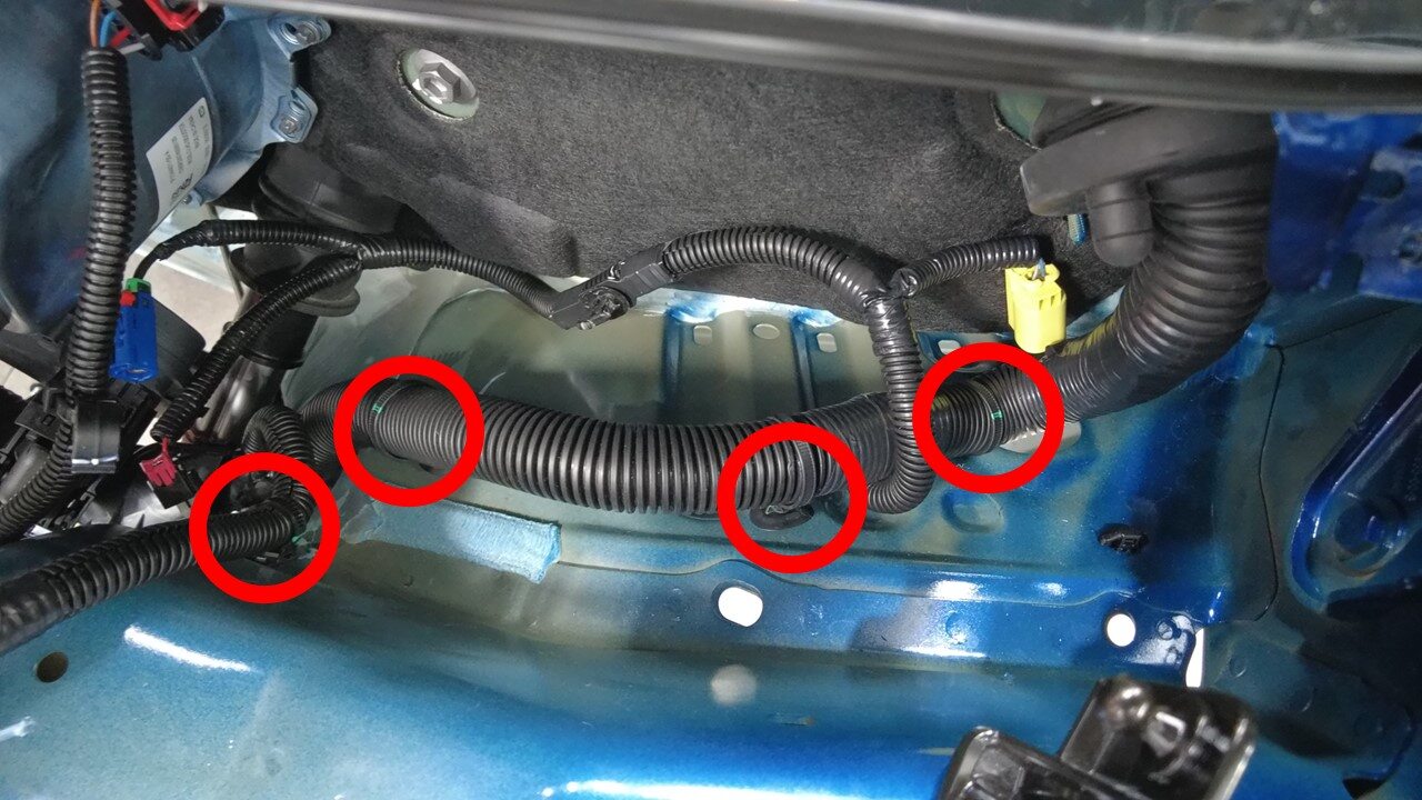
Release clips securing harness behind
LH shock tower
注4x clips
-
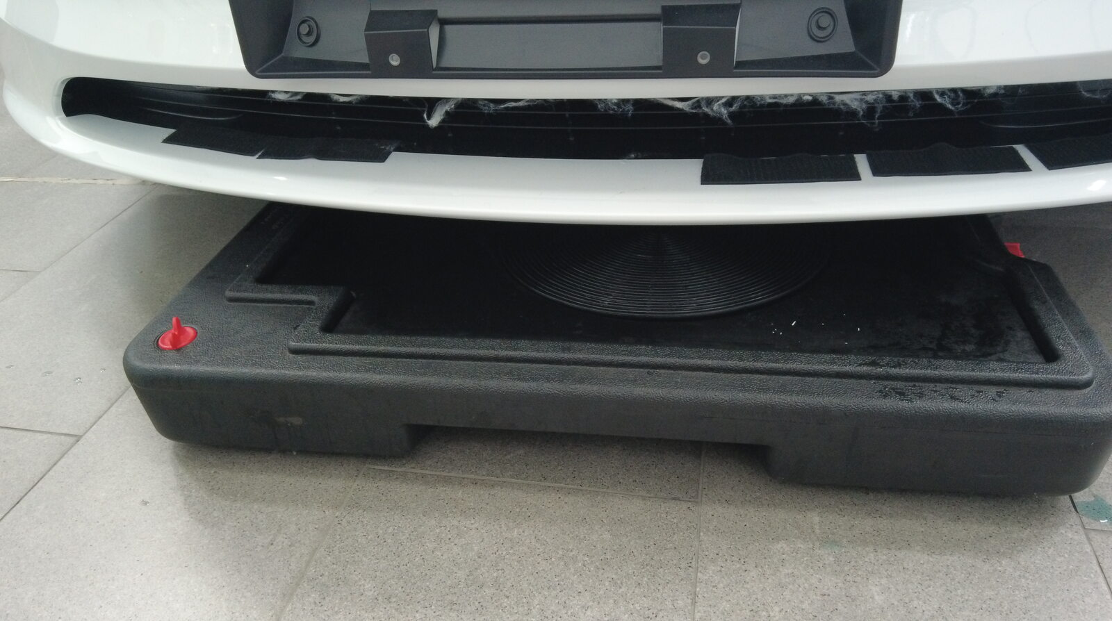
Position fluid catcher under
underneath vehicle
-
Place absorbent material underneath
brake booster and reservoir area

-
Remove fluid from brake fluid
reservoir
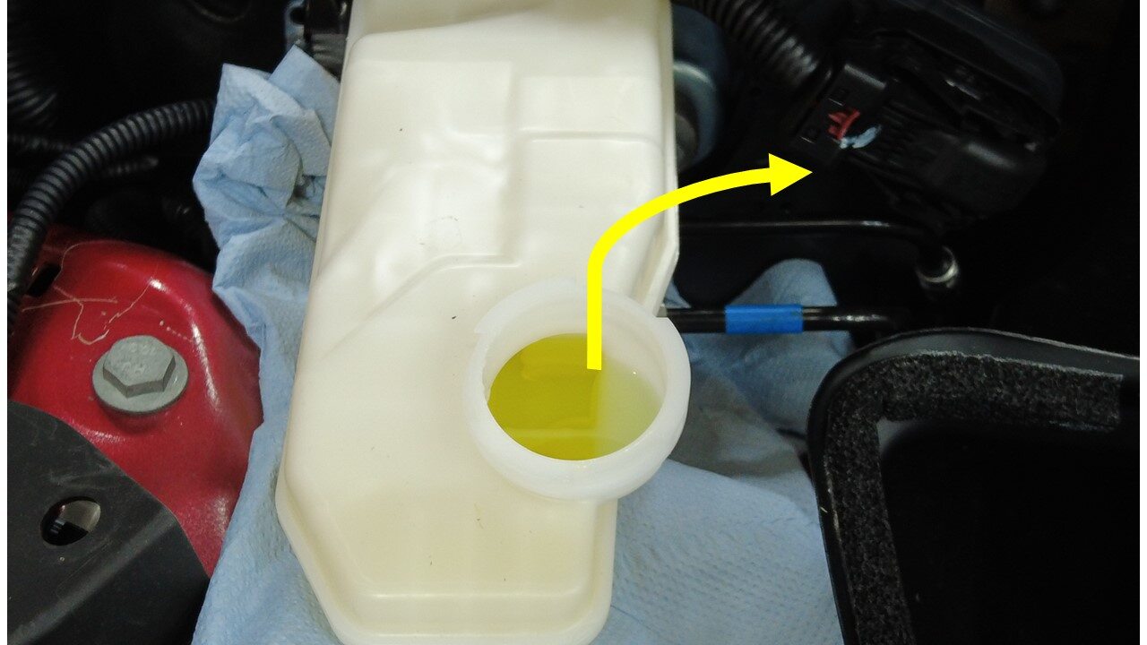
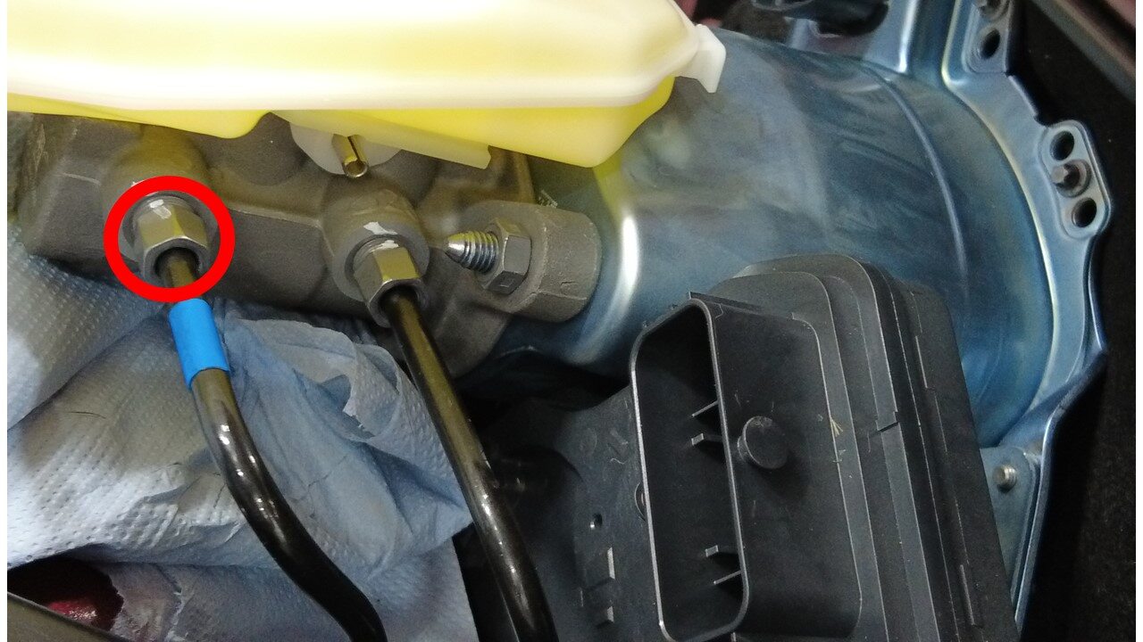
-
Disconnect forward brake line from
brake booster
注1x nut, 12mm, 16 Nm
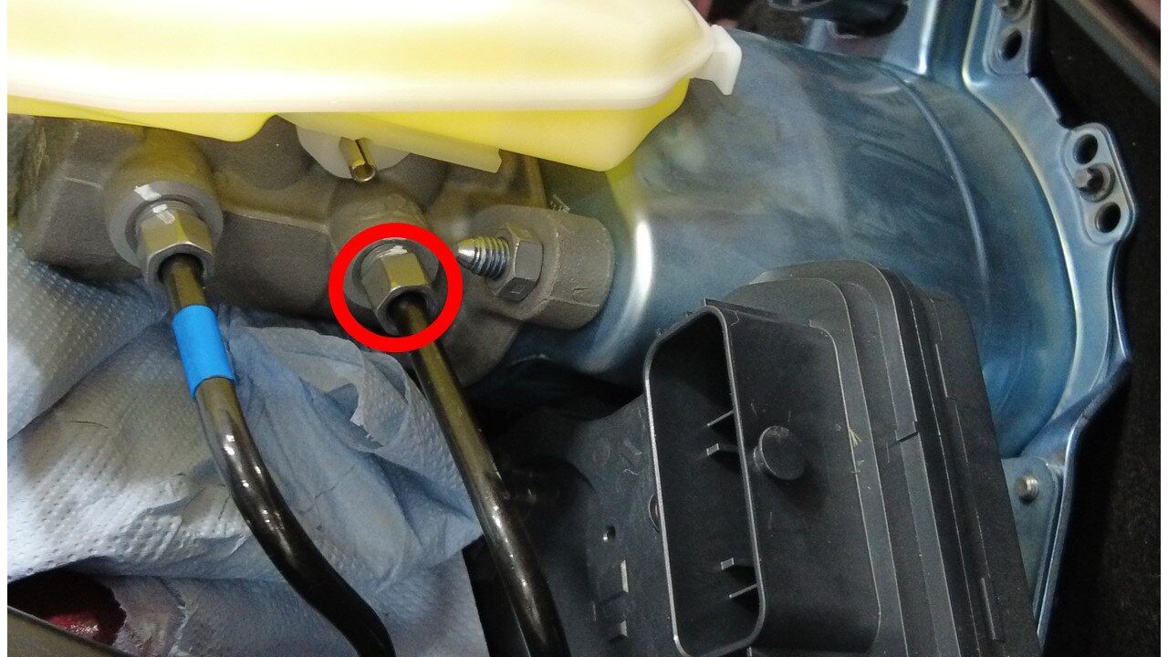
-
Disconnect rear brake line from brake
booster
注1x nut, 12mm, 16 Nm
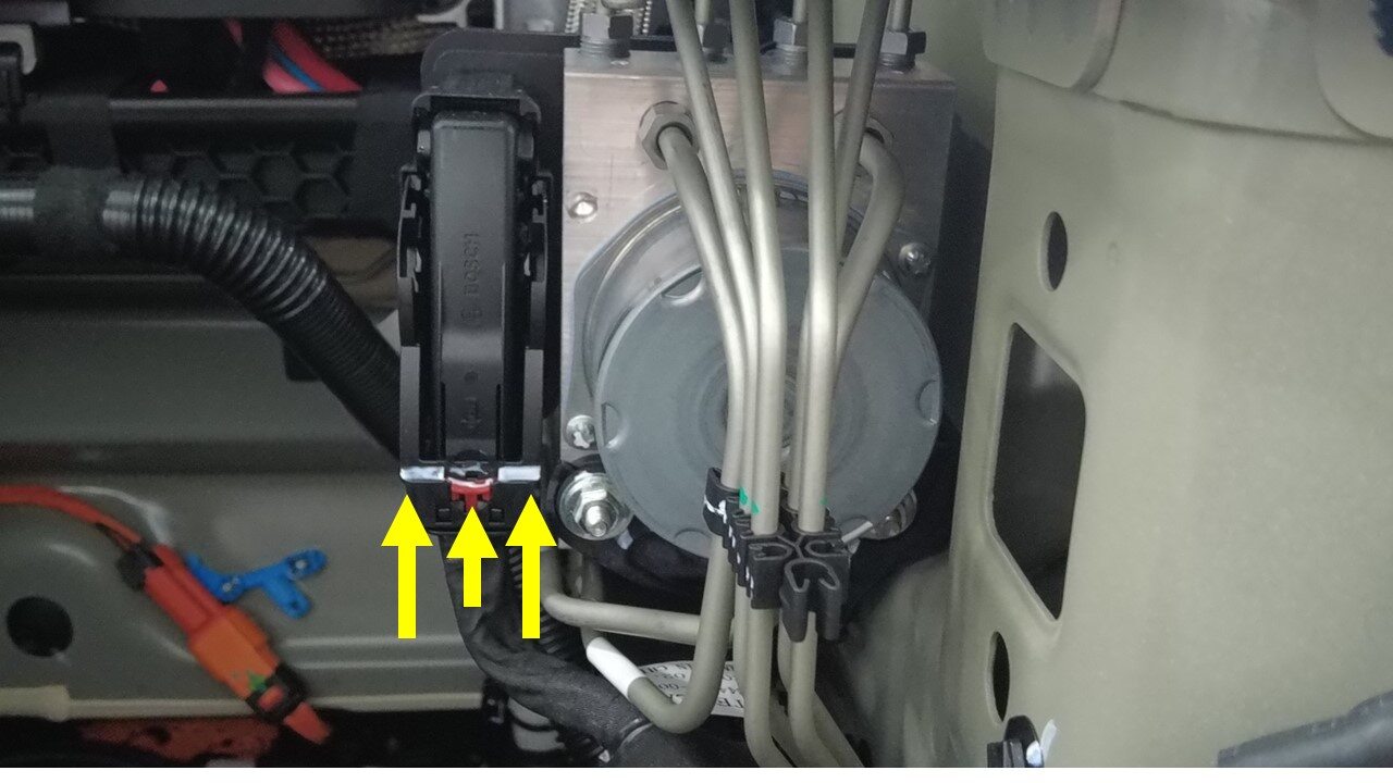
-
Disconnect the hydraulic control unit
connector
注1x connector, Disengage locking tab and pull up on connector to release
-
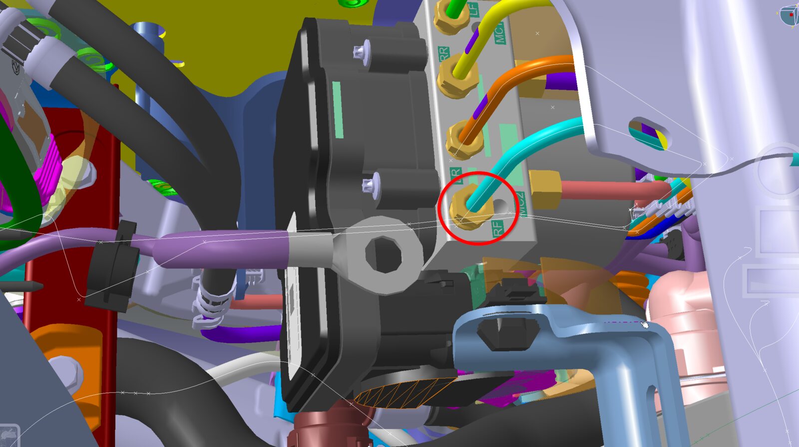
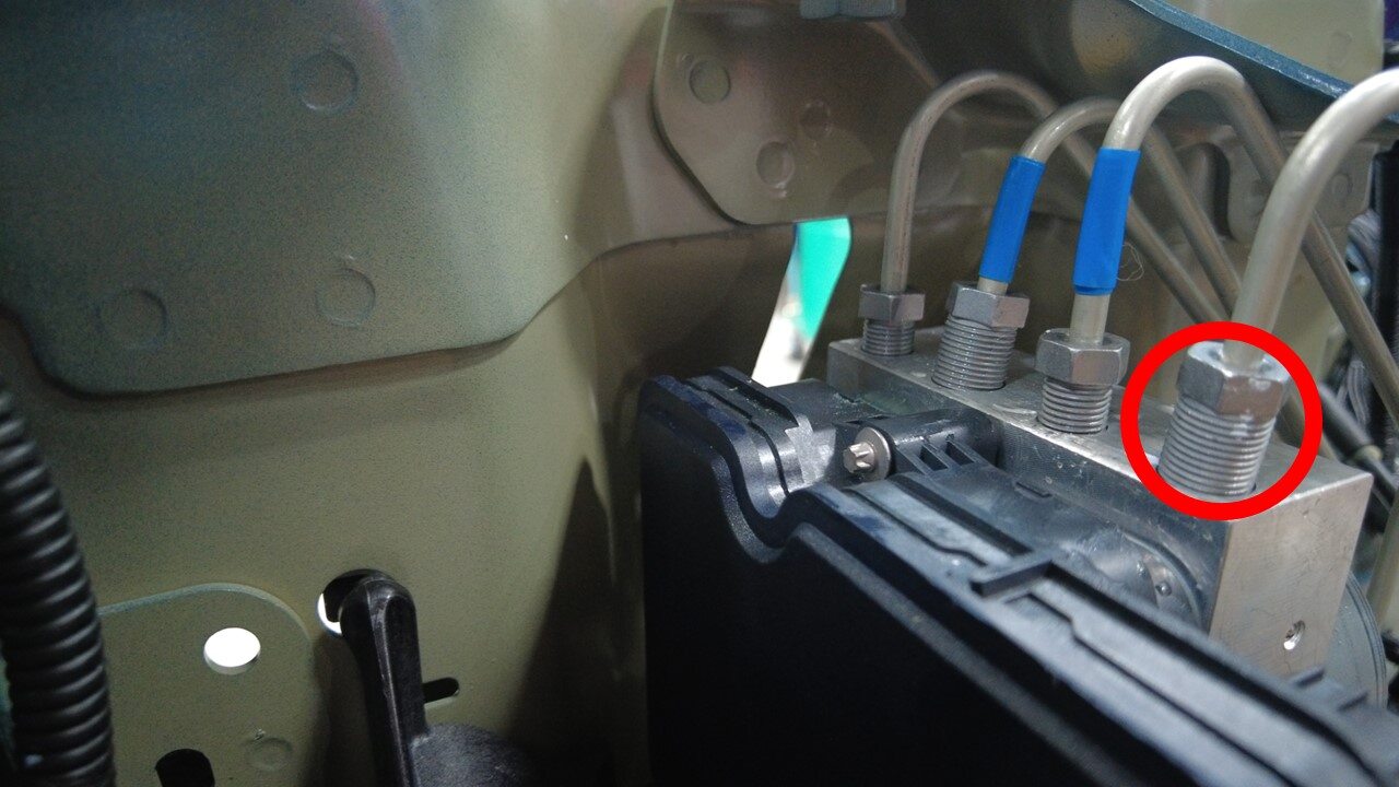
Remove RH front brake line tube nut
from hydraulic control unit
注1x nut, 12mm, 16 Nm
-
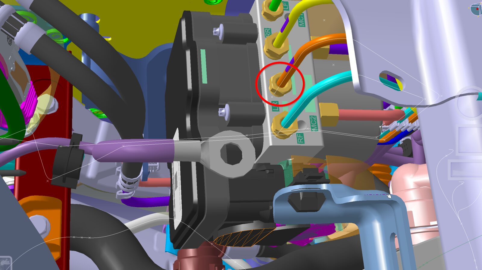
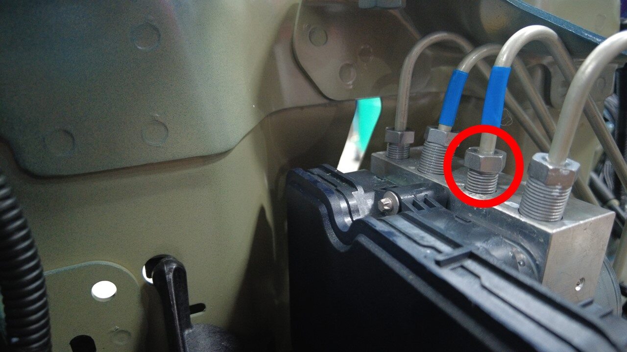
Remove the LH rear brake line tube nut
from hydraulic control unit
注1x nut, 12mm, 16 Nm
-
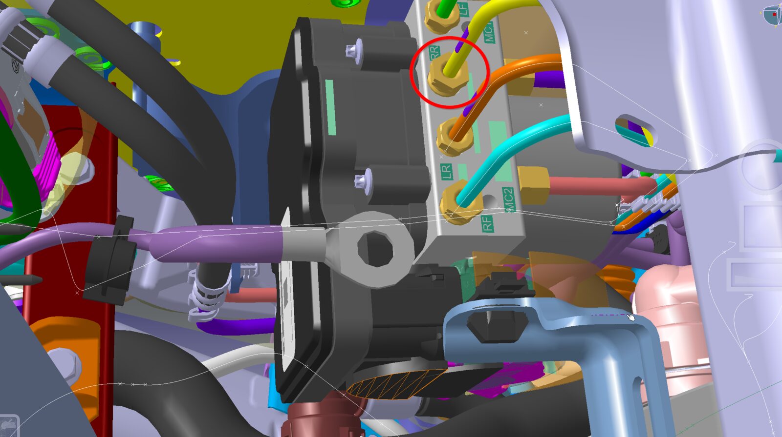
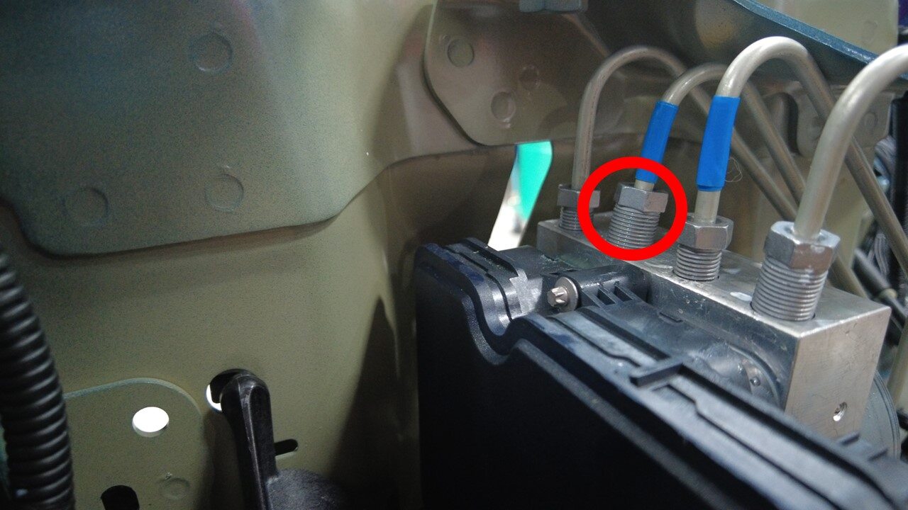
Remove RH rear brake line tube nut
from hydraulic control unit
注1x nut, 12mm, 16 Nm
-
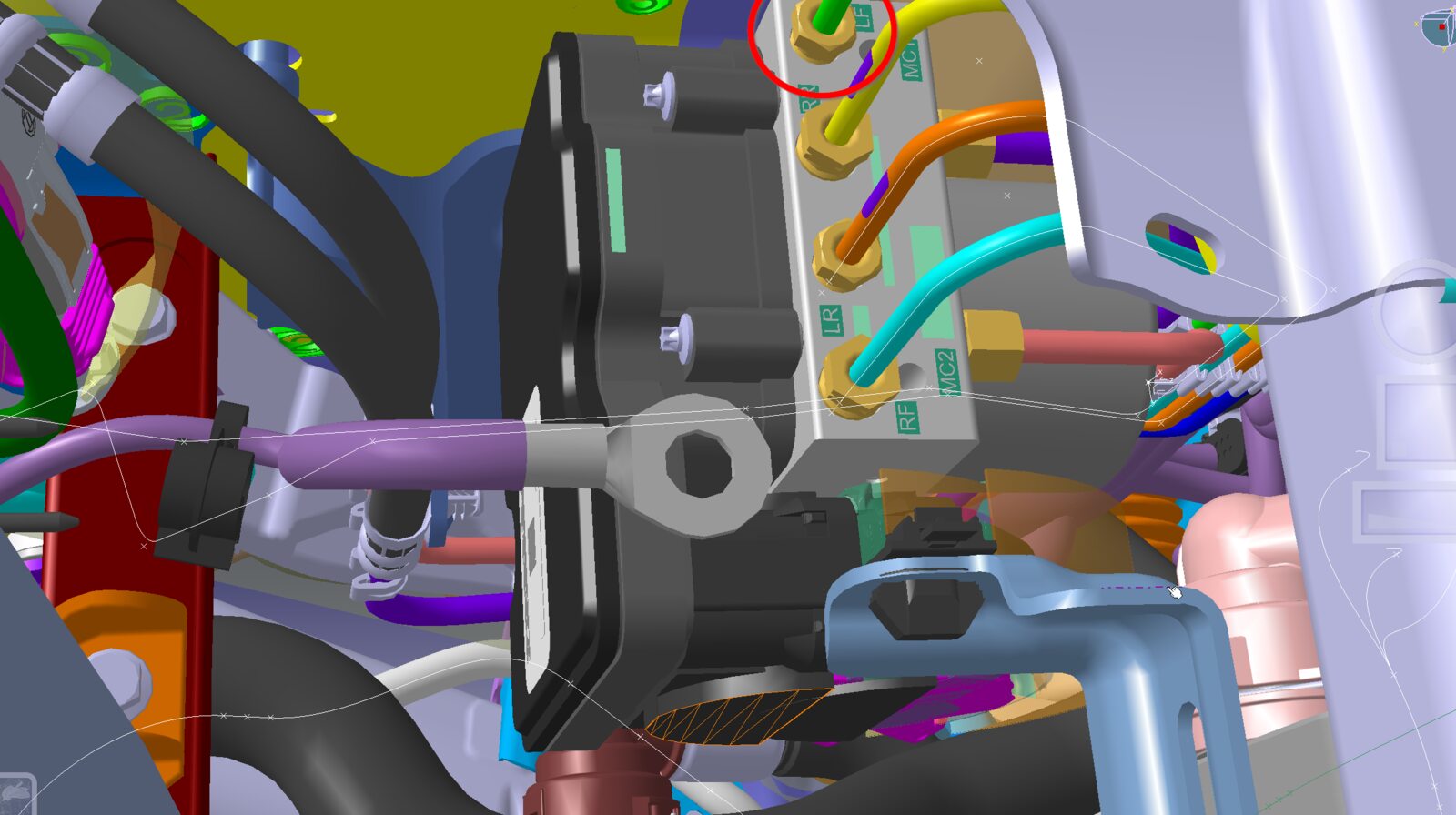
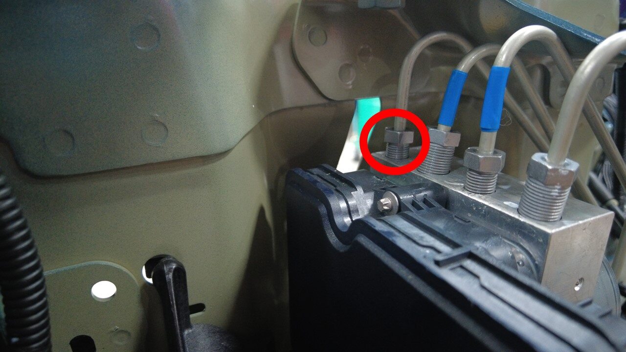
Remove LH front brake line tube nut
from hydraulic control unit
注1x nut, 12mm, 16 Nm
-
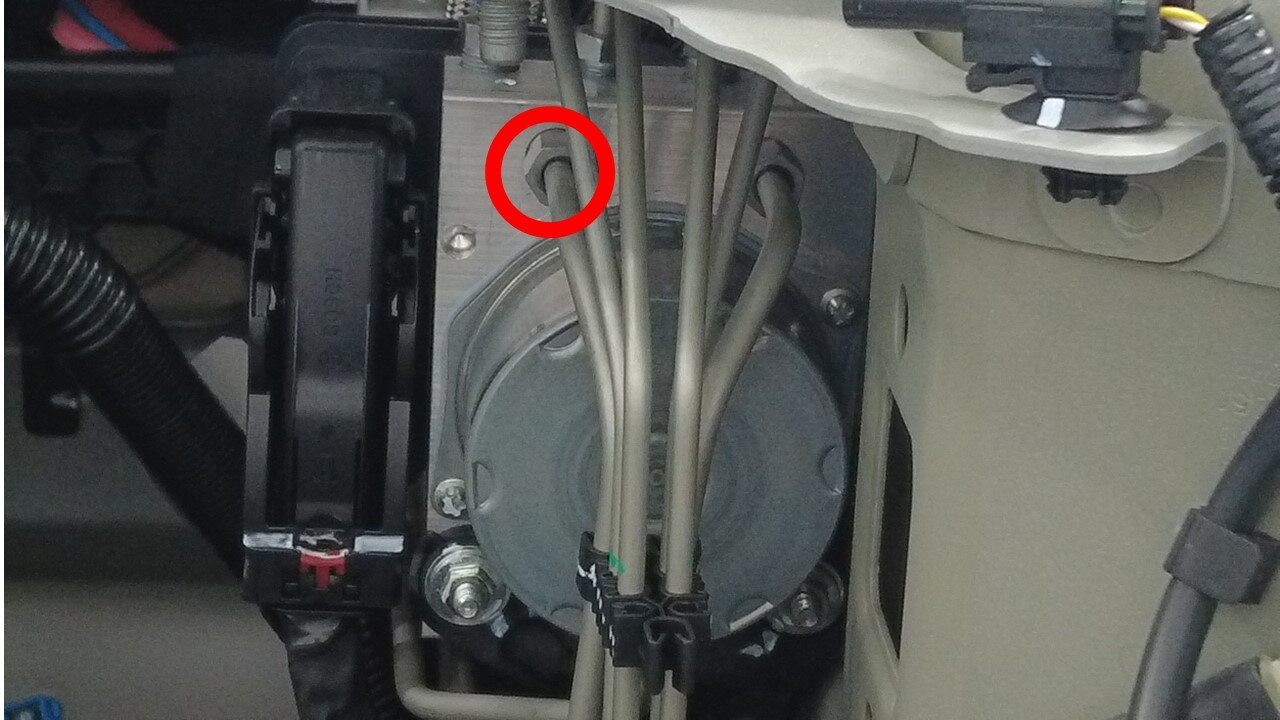
Remove the master cylinder secondary
pipe nut from hydraulic control unit
注1x nut, 12mm, 16 Nm
-
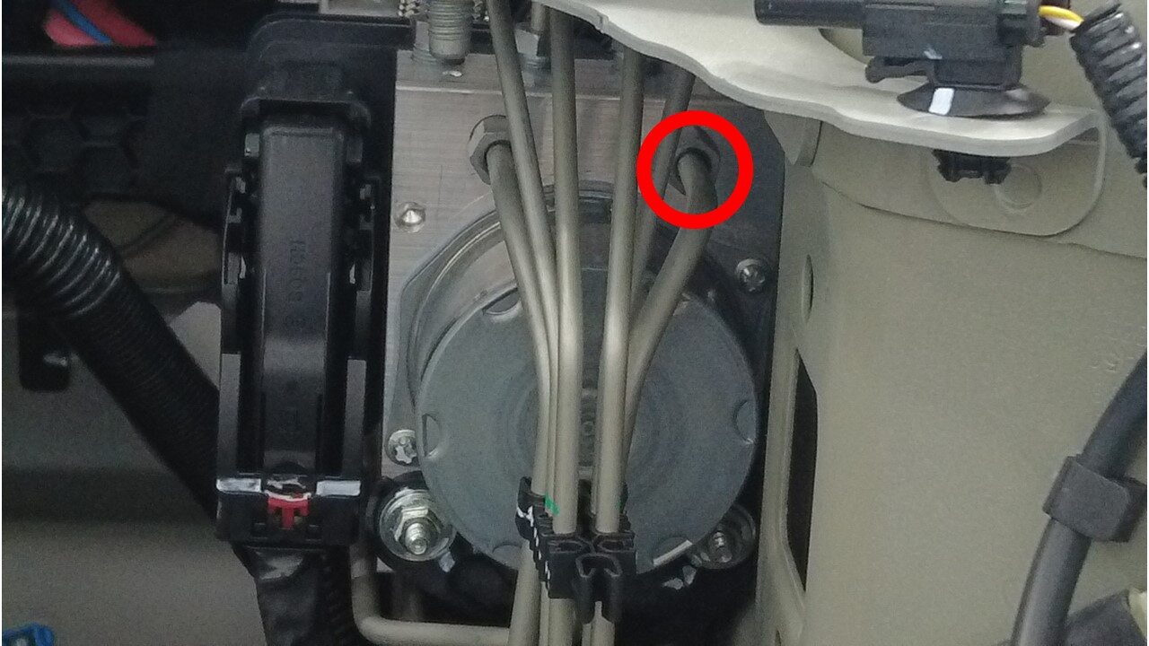
Remove the master cylinder primary
pipe nut from hydraulic control unit
注1x nut, 12mm, 16 Nm
-
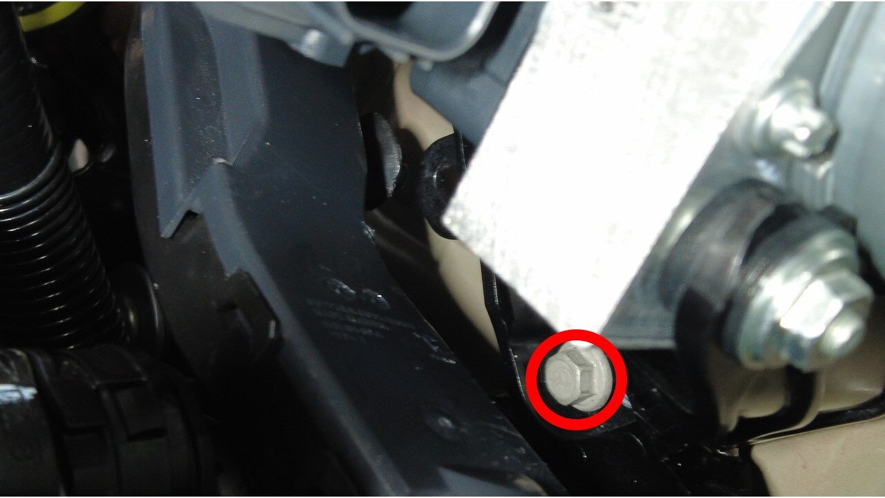
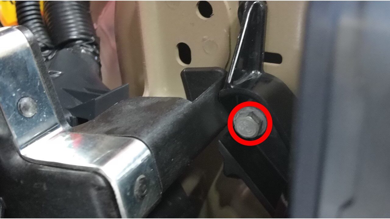
Remove bolts securing hydraulic
control unit bracket to frame rail
注2x bolts, 10mm, 10 Nm
-
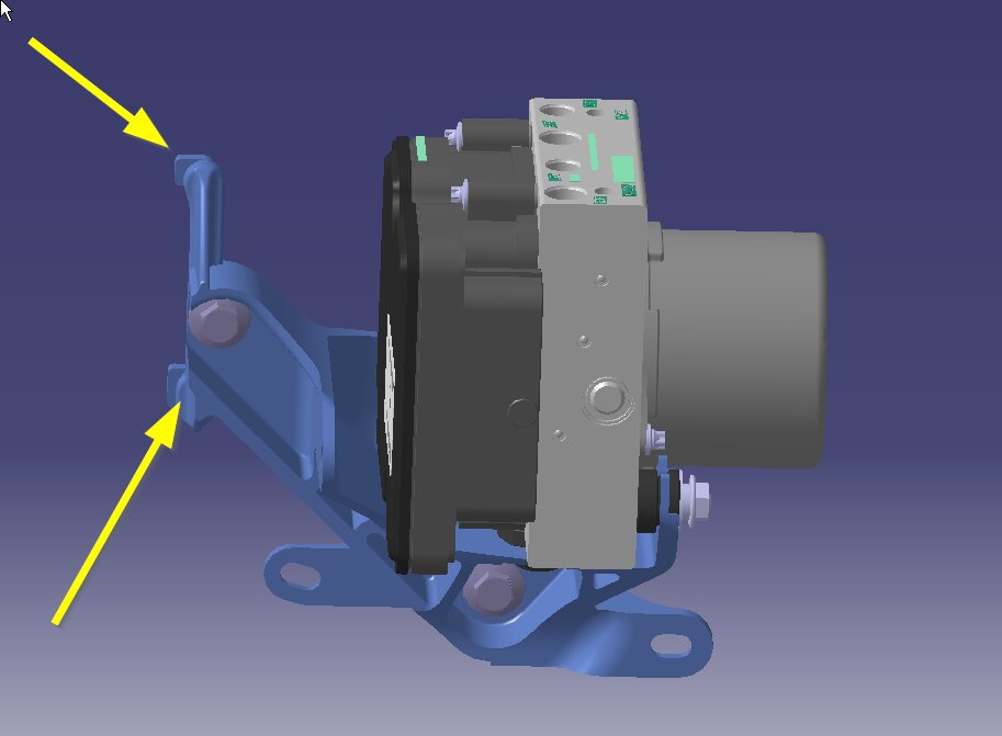
Remove hydraulic control unit and
bracket from vehicle
注2x tabs

-
Place absorbent material below car
computer coolant hose connection points to collect any spilled coolant
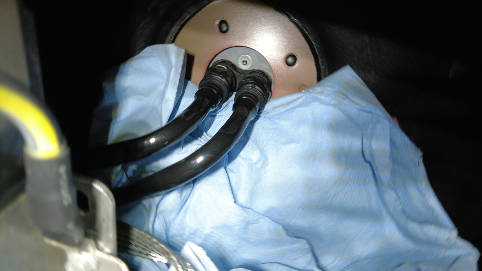
-
Disconnect outer coolant hose from car
computer mount
注1x spring clip, Plug hose
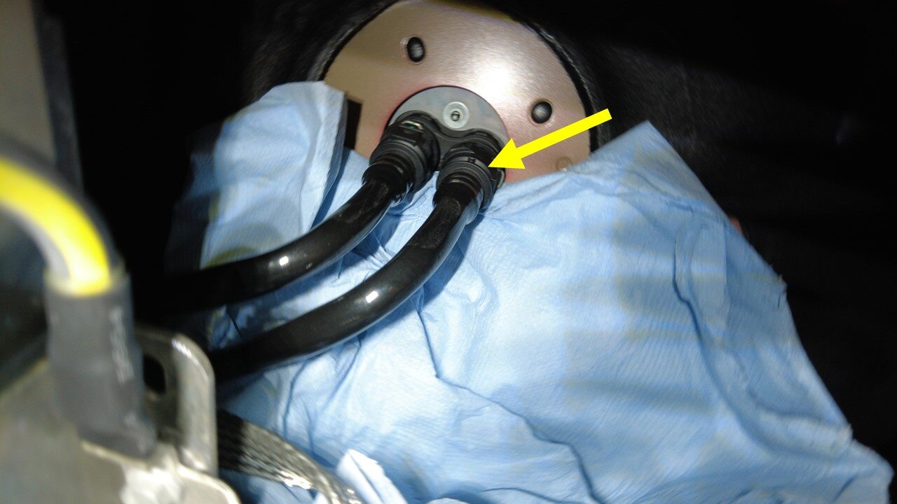
-
Disconnect inner coolant hose to car
computer mount and remove coolant hoses from car computer
注1x spring clip, Plug hose
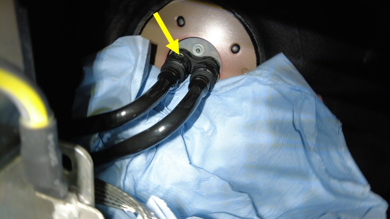
-
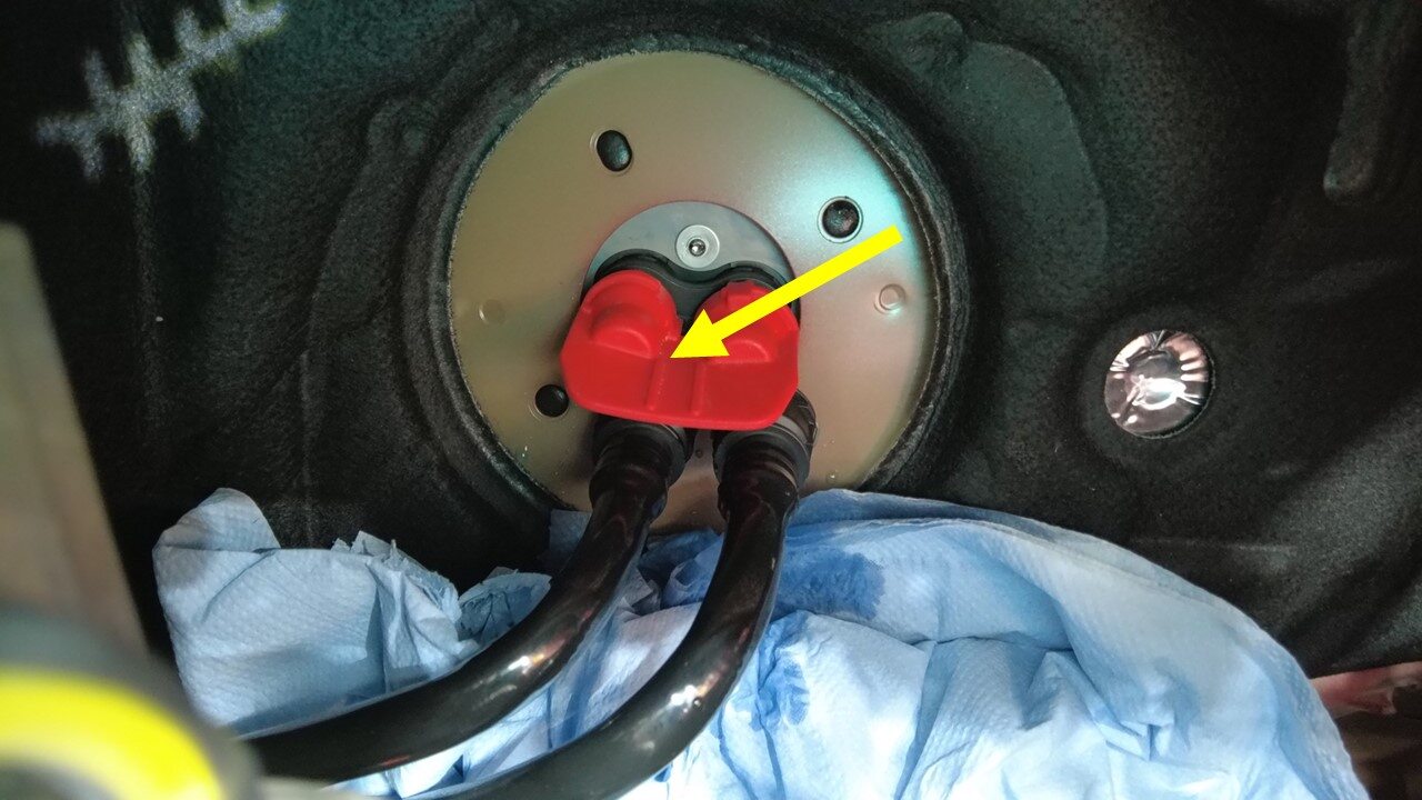
Install car computer coolant
plug
注1x coolant plug
-
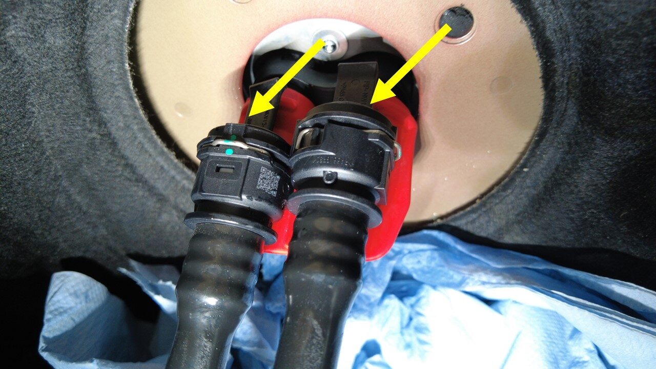
Install plugs to car computer coolant
hoses
注2x plugs, Do not need to engage spring clips
-
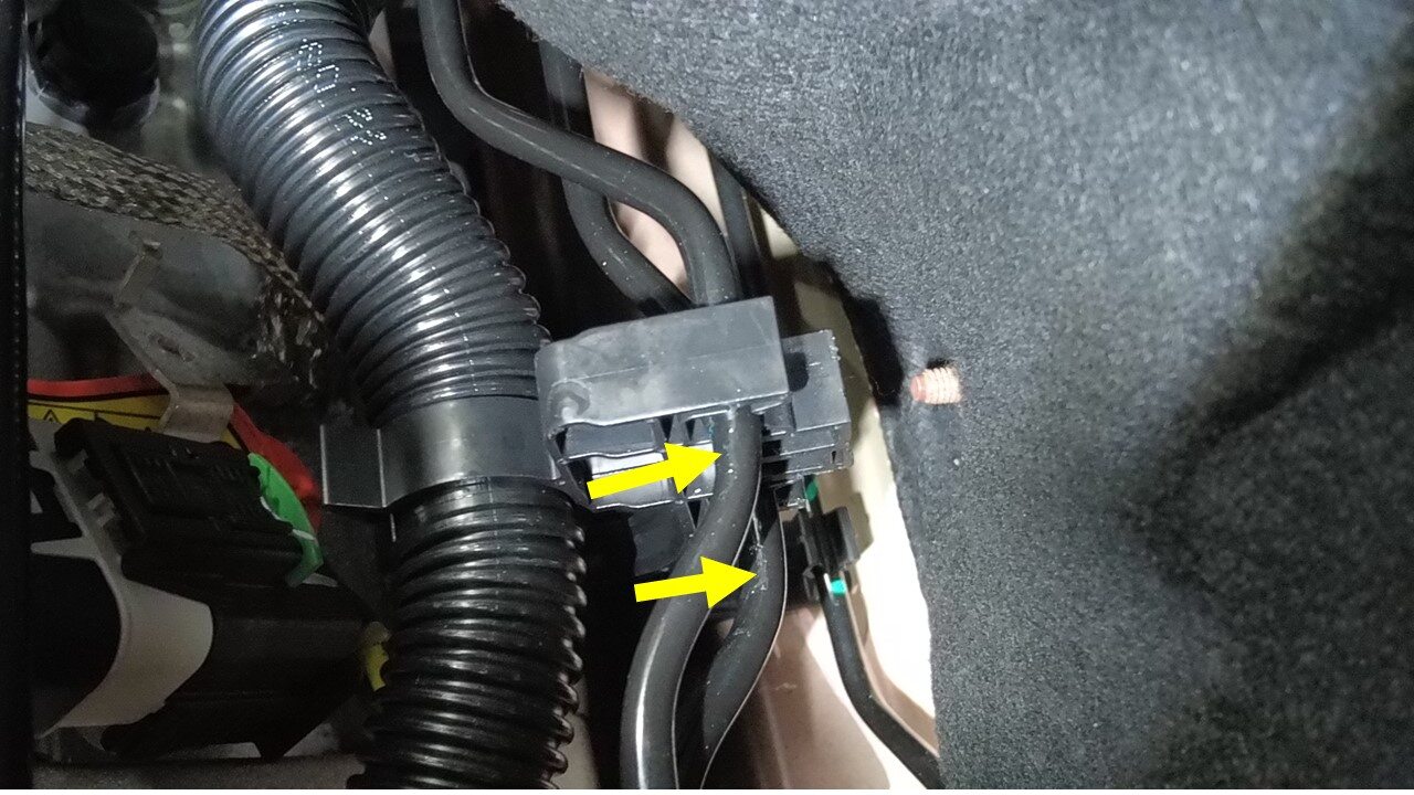
Release primary and secondary pipe
from bundle clip

-
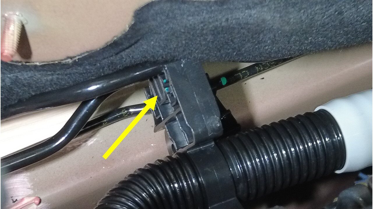
Release LH bundle clip from body
注Be careful with water pipe during disassembly
-
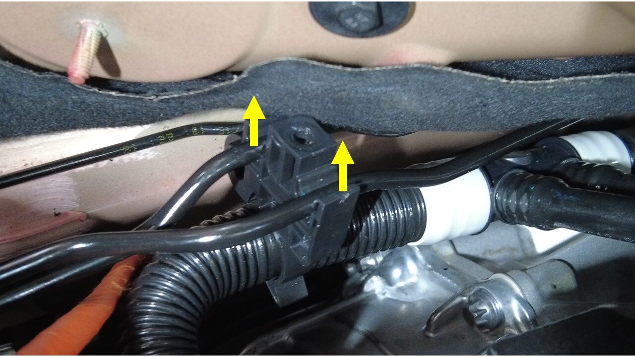
Release primary and secondary pipe
from LH bundle clip
-
Release RH bundle clip from body
注Be careful with water pipe during disassembly

-
Release primary and secondary pipe
from RH bundle clip
-
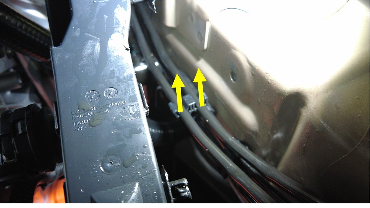
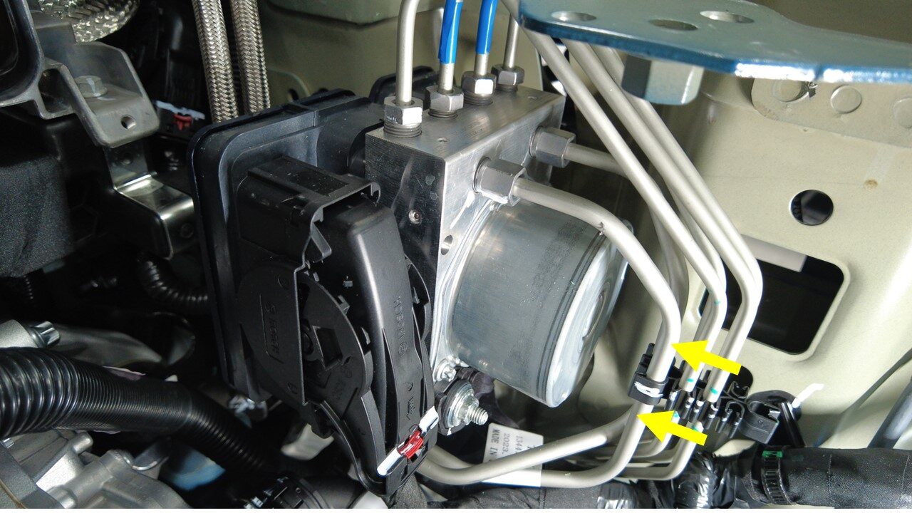
Release primary and secondary pipe
from bundle clips
注2x clips
-
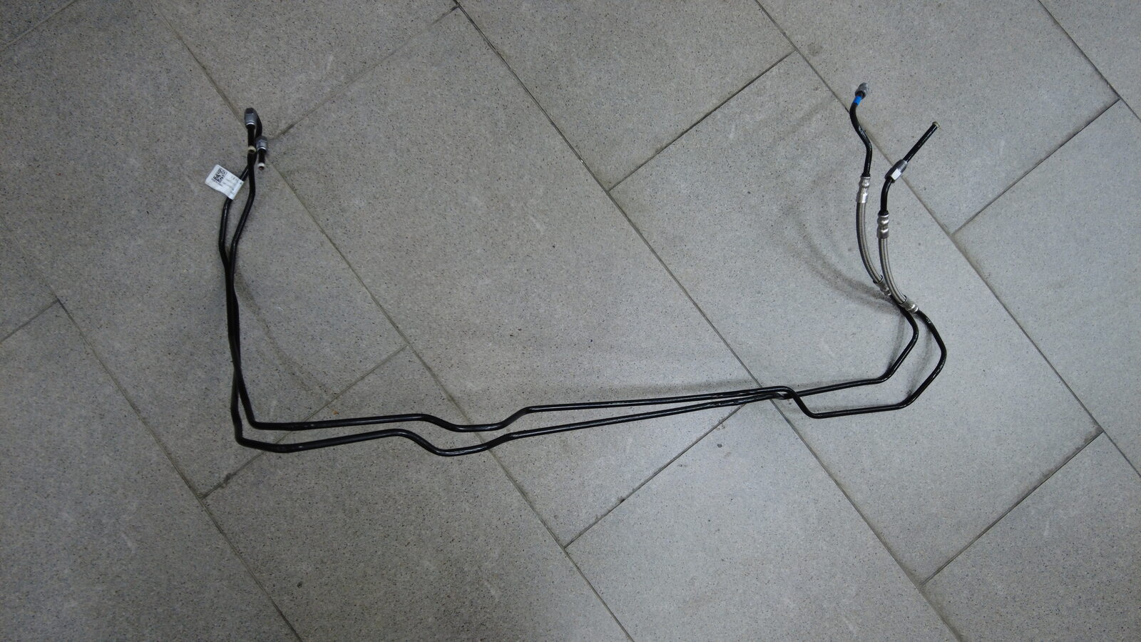
Remove brake line bundle from
vehicle
注Move right side of pipeline upwards, pass through wiring harness, and take it out from right side


安装
-
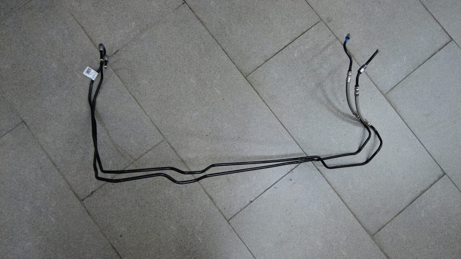
Install brake line bundle to
vehicle
-
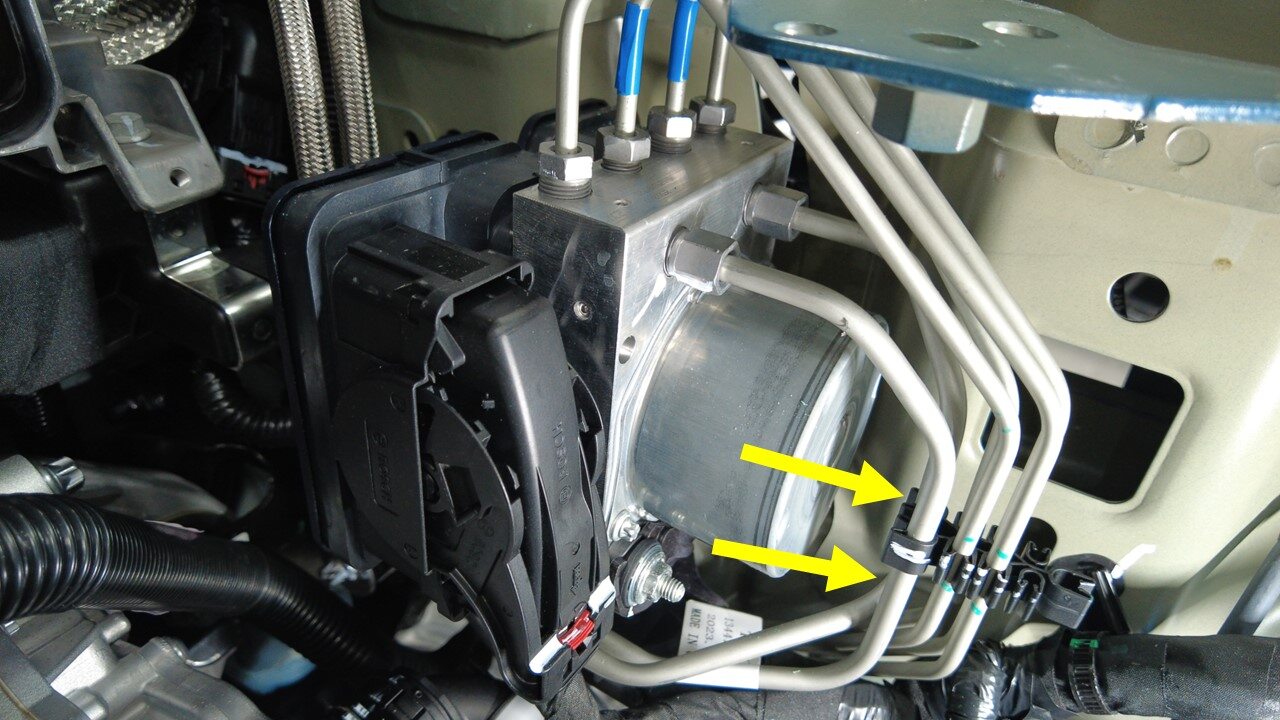
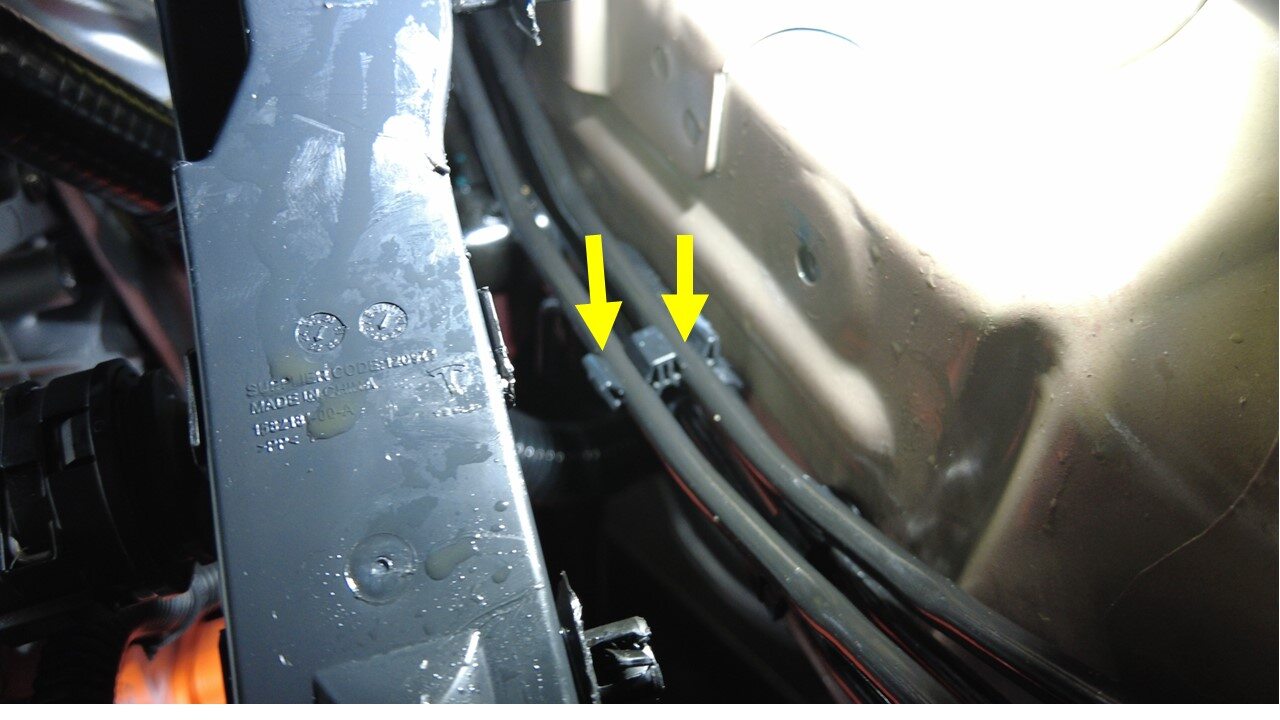
Install primary and secondary pipe to
bundle clips
注2x clips
-
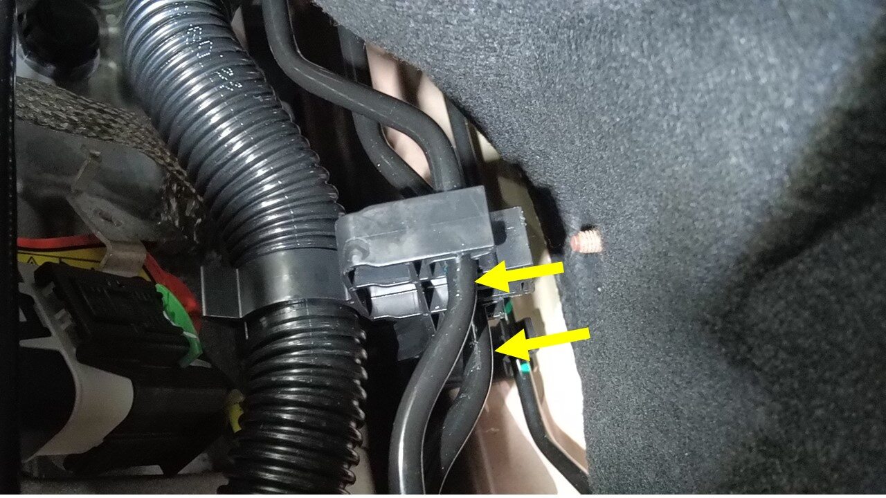
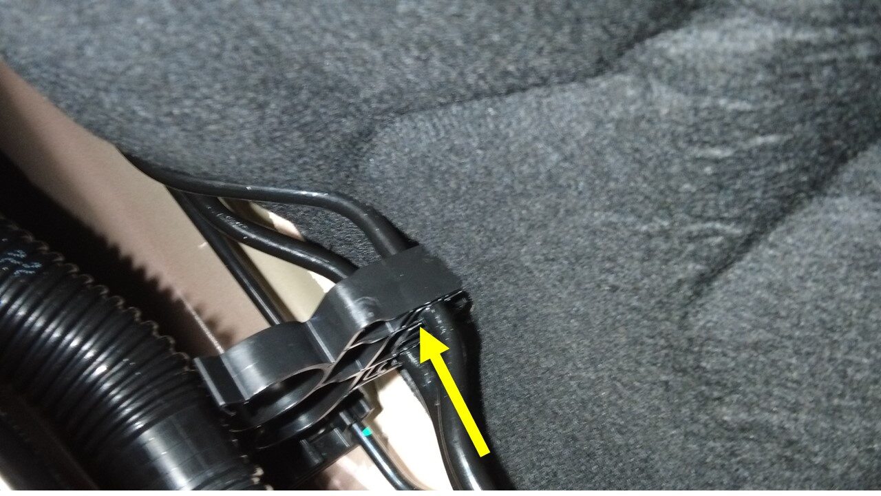
Install primary and secondary pipe to
RH bundle clip
-
Install RH bundle clip to body
注Be careful with water pipe during disassembly
-
Install primary and secondary pipe to
LH bundle clip
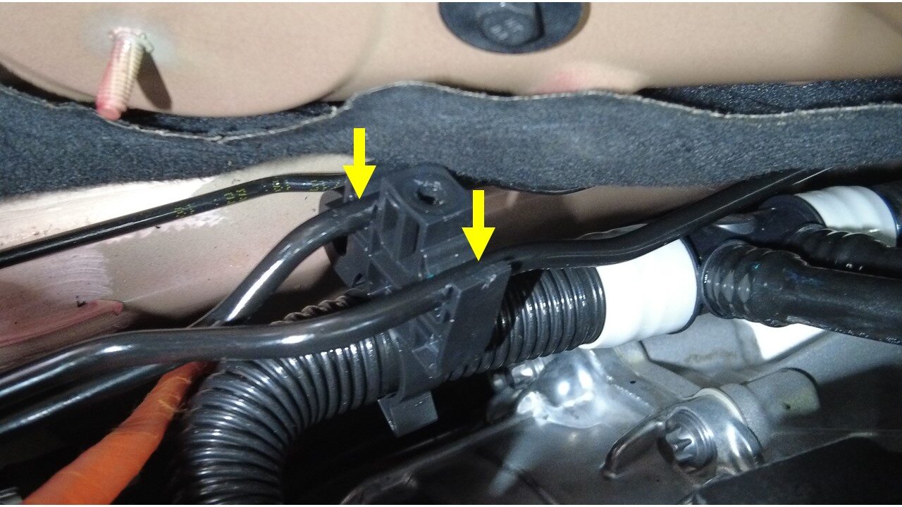
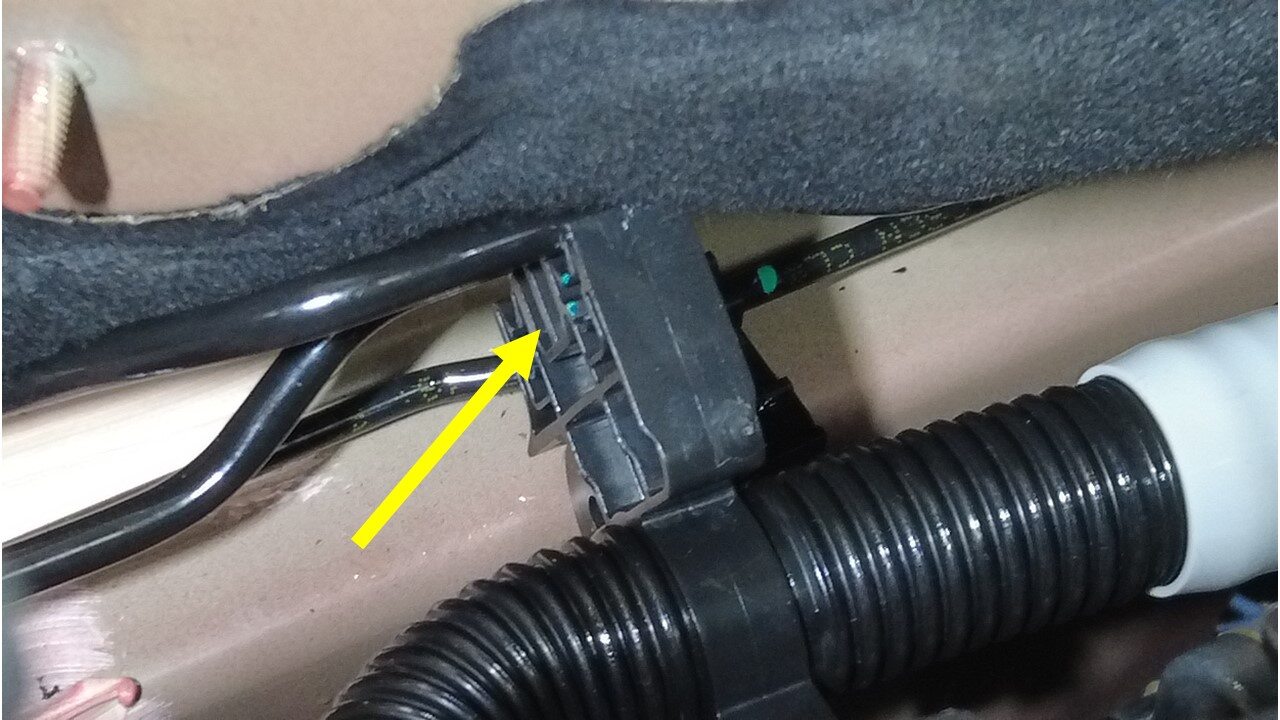
-
Install LH bundle clip to body
注Be careful with water pipe during disassembly
-
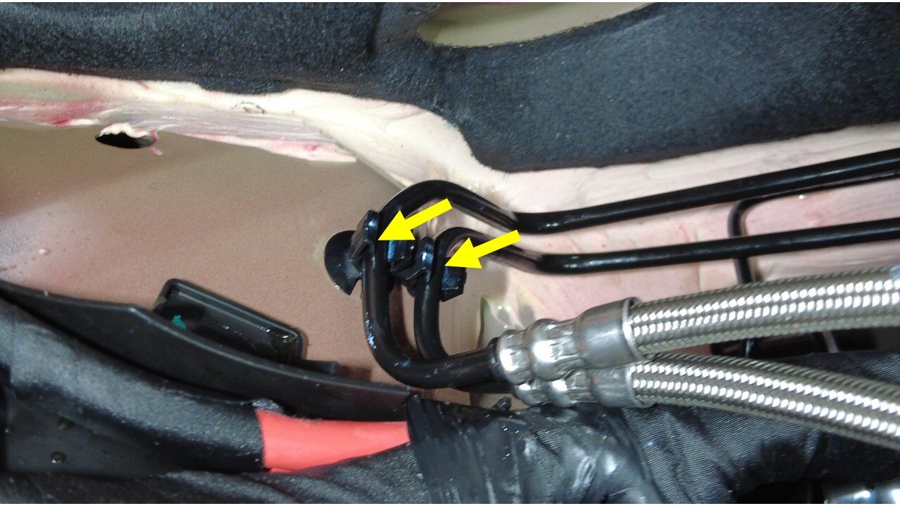
Install primary and secondary pipe to
bundle clip
-
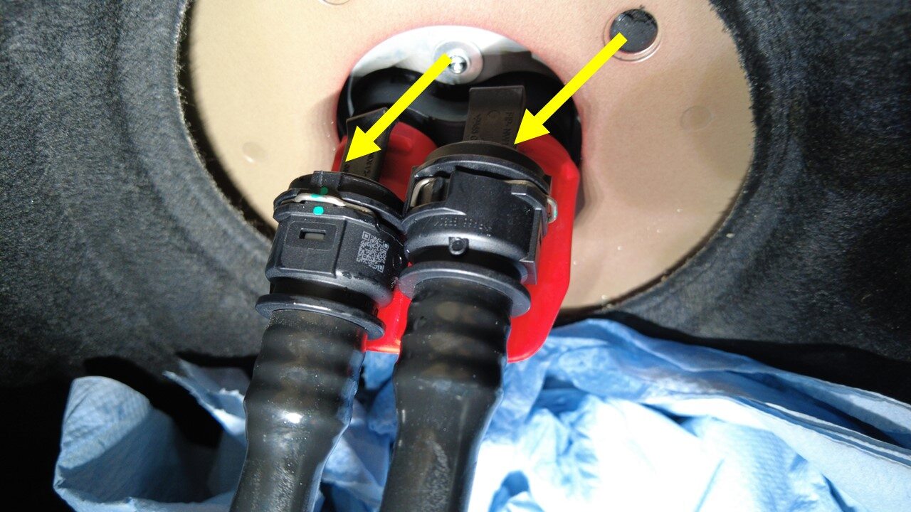
Remove plugs to car computer coolant
hoses
注2x plugs, Do not need to engage spring clips
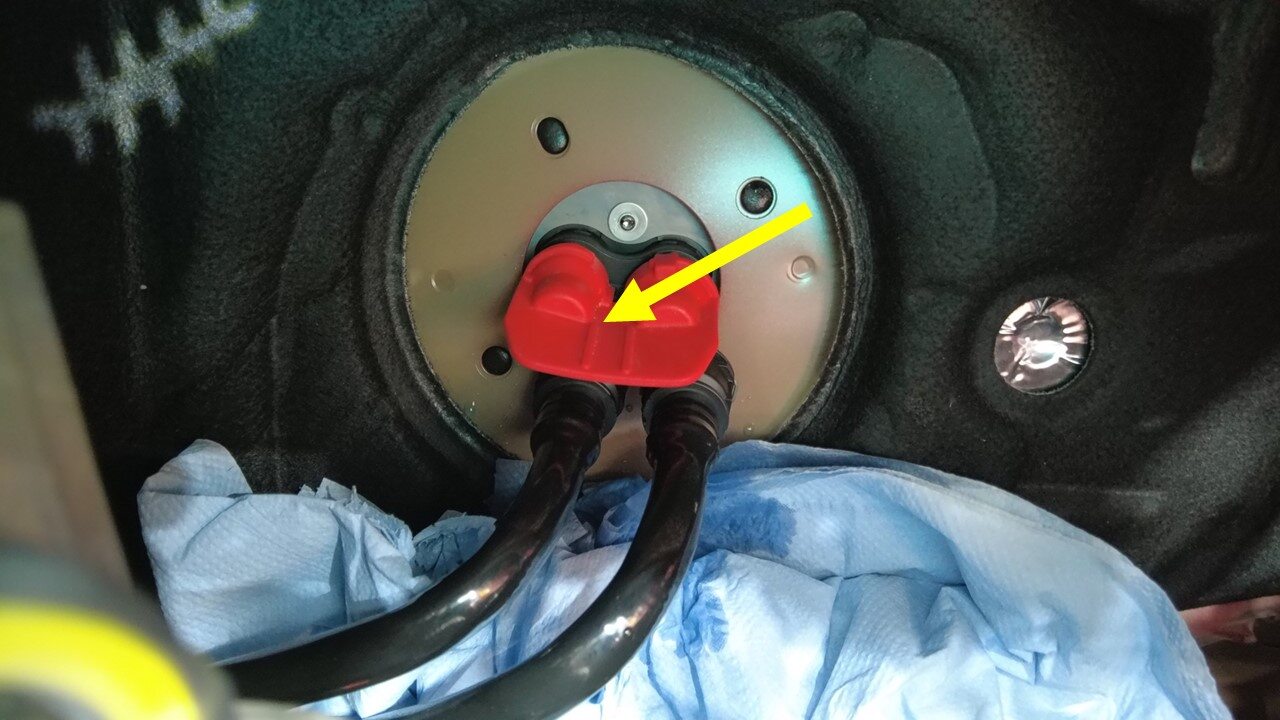
-
Remove coolant plug from car
computer
注1x coolant plug
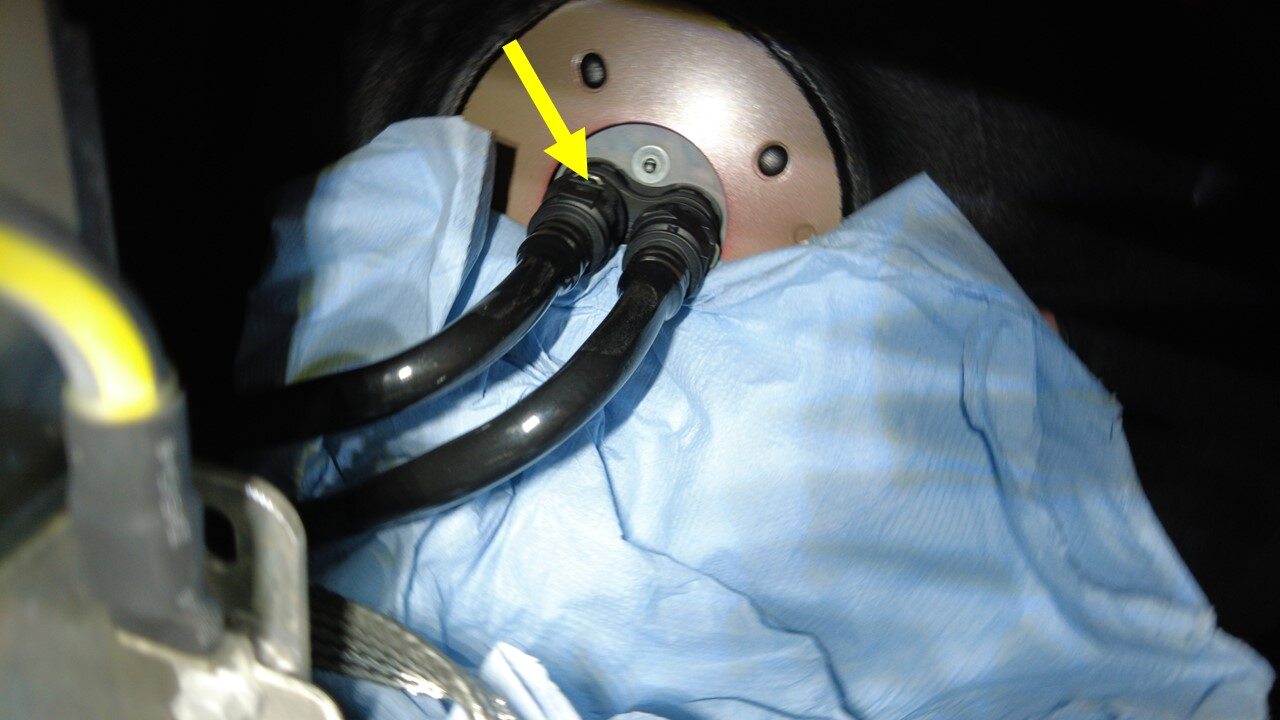
-
Install inner coolant hose to car
computer mount
注1x spring clip, Plug hose
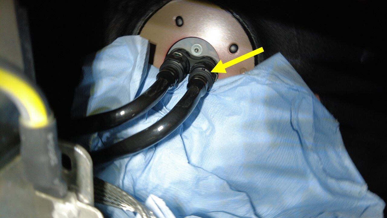
-
Install outer coolant hose to car
computer mount
注1x spring clip, Plug hose
-
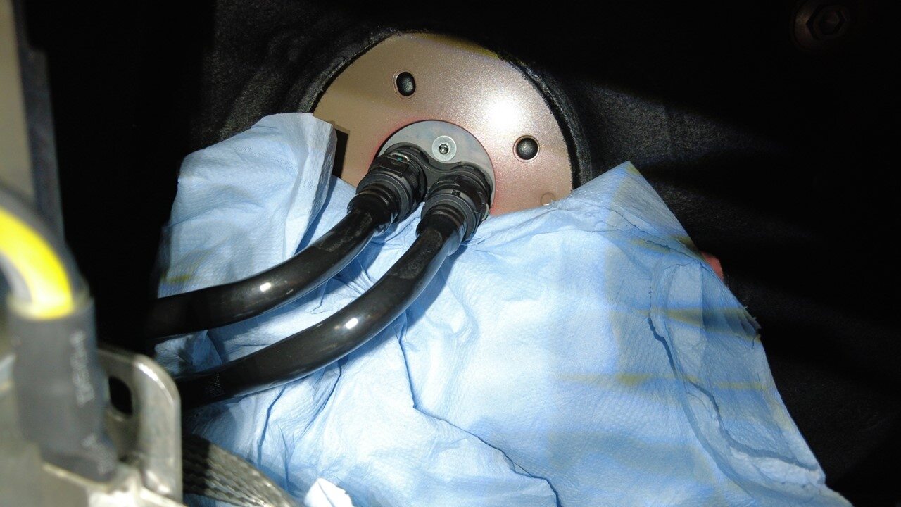
Remove absorbent material
-
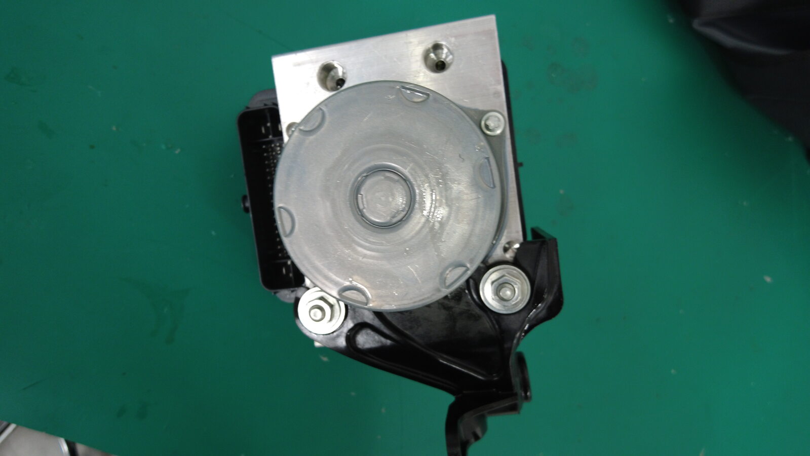
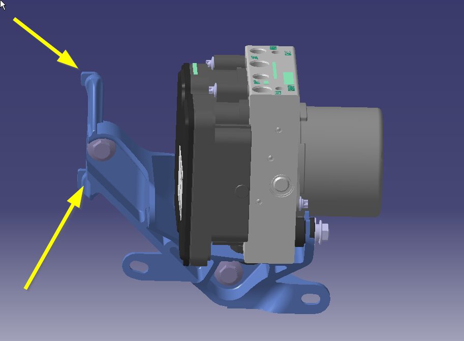
Install hydraulic control unit and
bracket to vehicle
注2x tabs
-
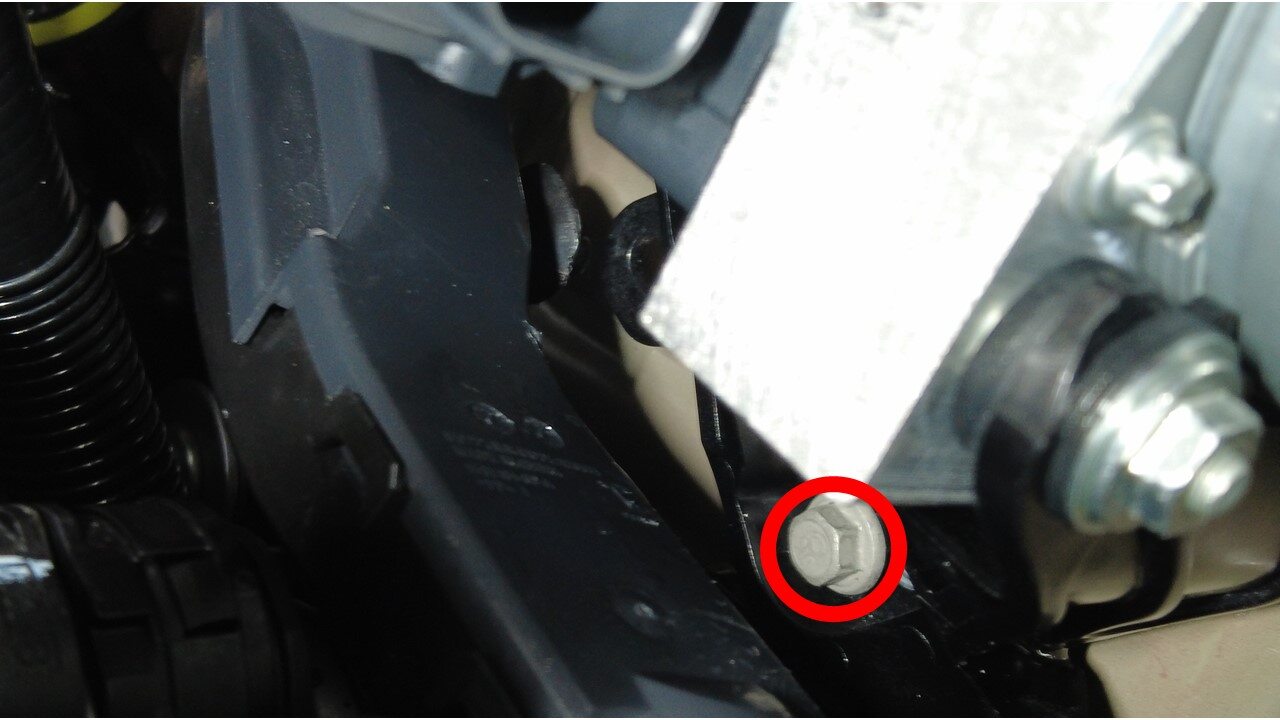
Install bolts securing hydraulic
control unit bracket to frame rail
注2x bolts, 10mm, 10 Nm

-
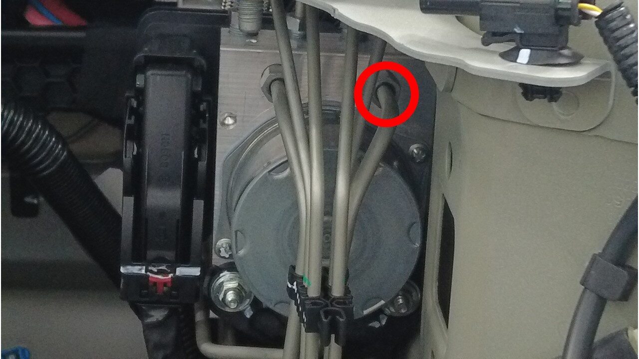
Install the master cylinder primary
pipe nut to hydraulic control unit
注1x nut, 12mm, 16 Nm
-
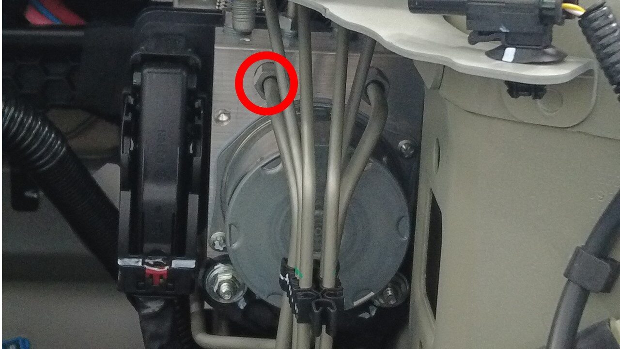
Install the master cylinder secondary
pipe nut to hydraulic control unit
注1x nut, 12mm, 16 Nm
-
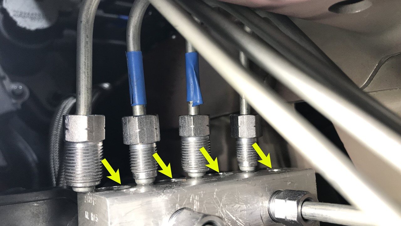
Move master cylinder lines into
position for installation
-
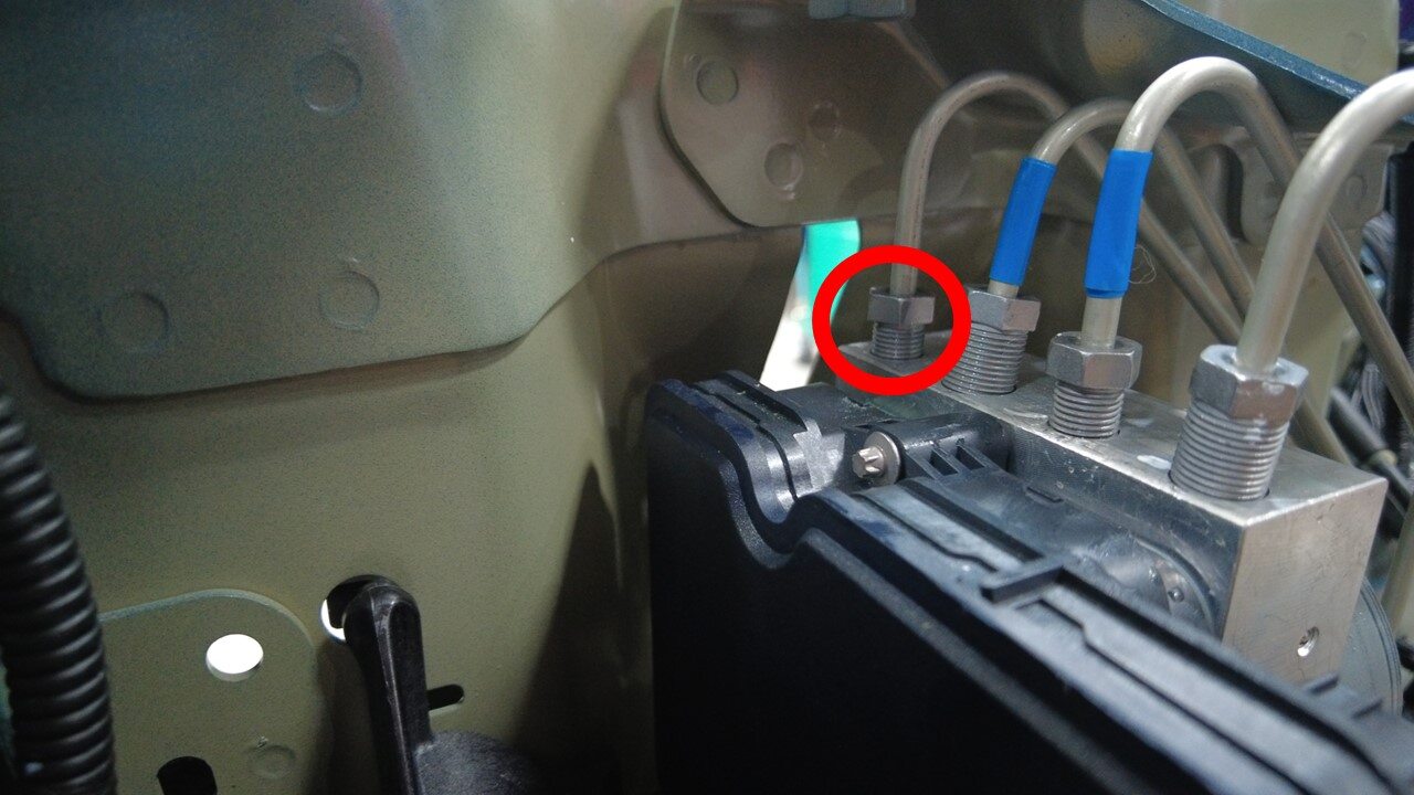
Install LH front brake line tube nut
to hydraulic control unit
注1x nut, 12mm, 16 Nm
-
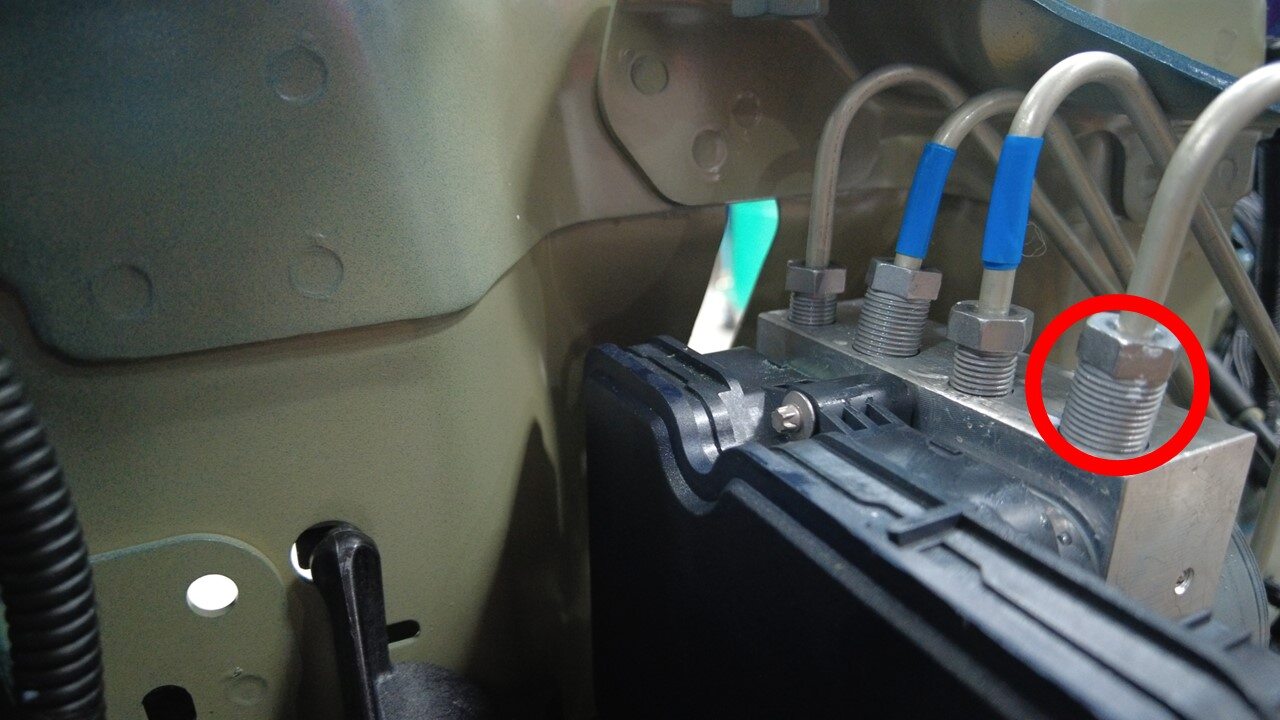
Install RH front brake line tube nut
to hydraulic control unit
注1x nut, 12mm, 16 Nm
-
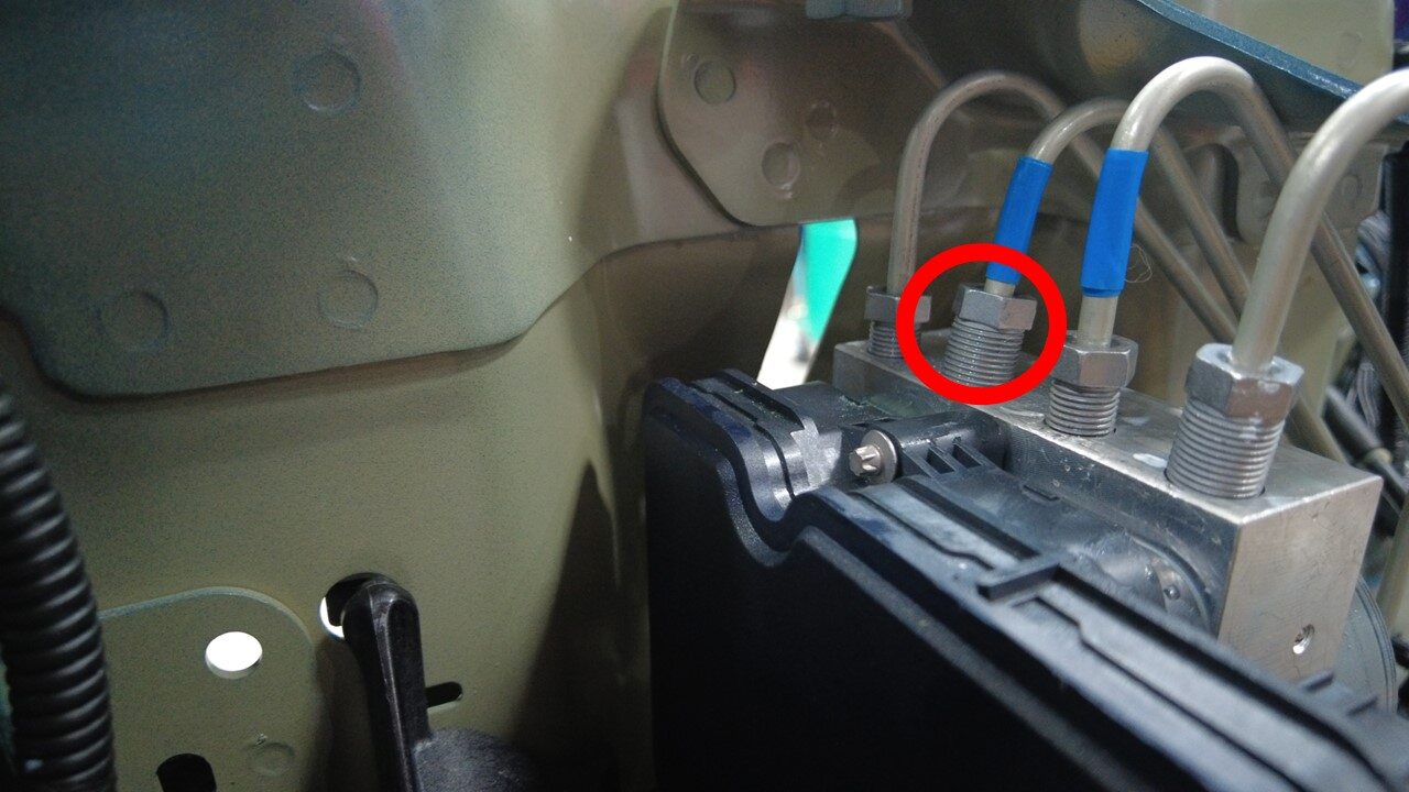
Install RH rear brake line tube nut to
hydraulic control unit
注1x nut, 12mm, 16 Nm
-
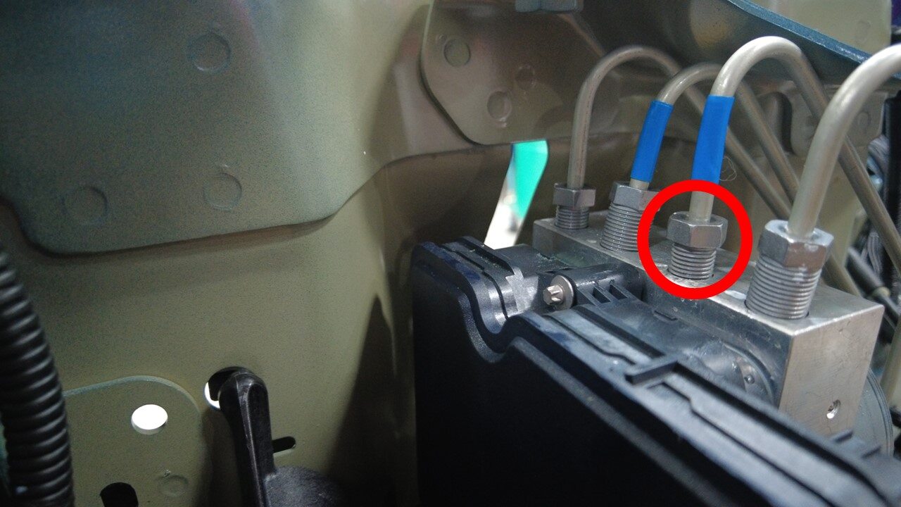
Install LH rear brake line tube nut to
hydraulic control unit
注1x nut, 12mm, 16 Nm
-
Install RH front brake line tube nut
to hydraulic control unit
注1x nut, 12mm, 16 Nm
-
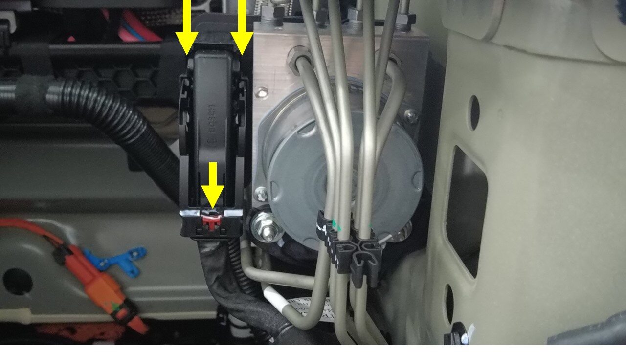
Connect the hydraulic control unit
connector
注1x connector, Gently push connector downward, Engage locking tab
-
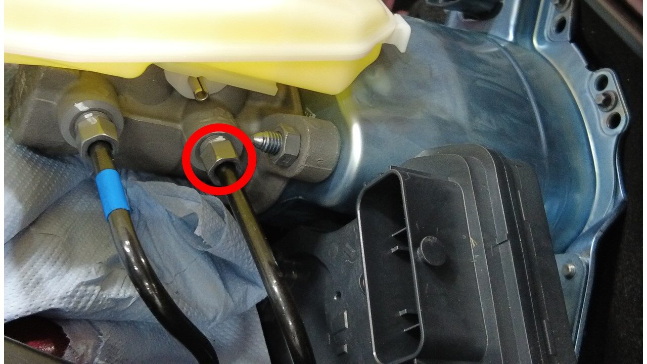
Connect rear brake line into brake
booster
注1x nut, 12mm, 16 Nm
-
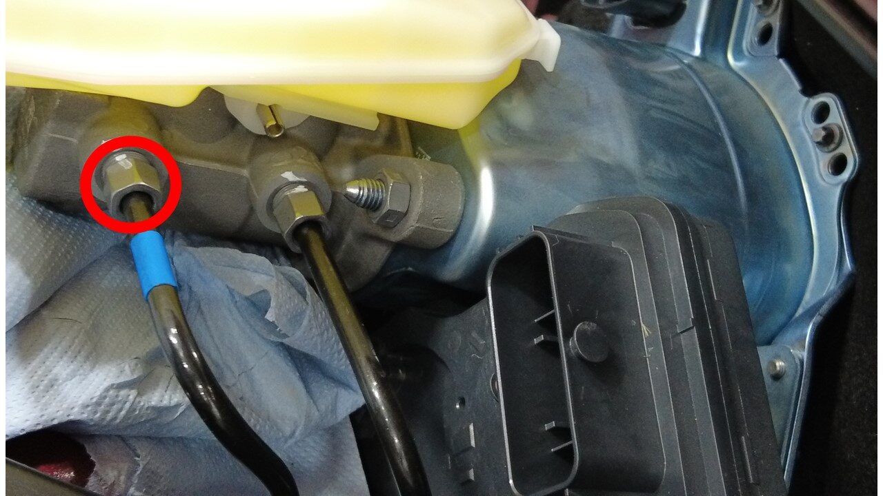
Connect forward brake line into brake
booster
注1x nut, 12mm, 16 Nm
-
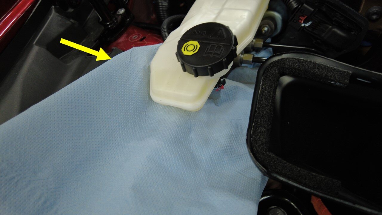
Remove absorbent material from
underneath brake booster and reservoir area
-
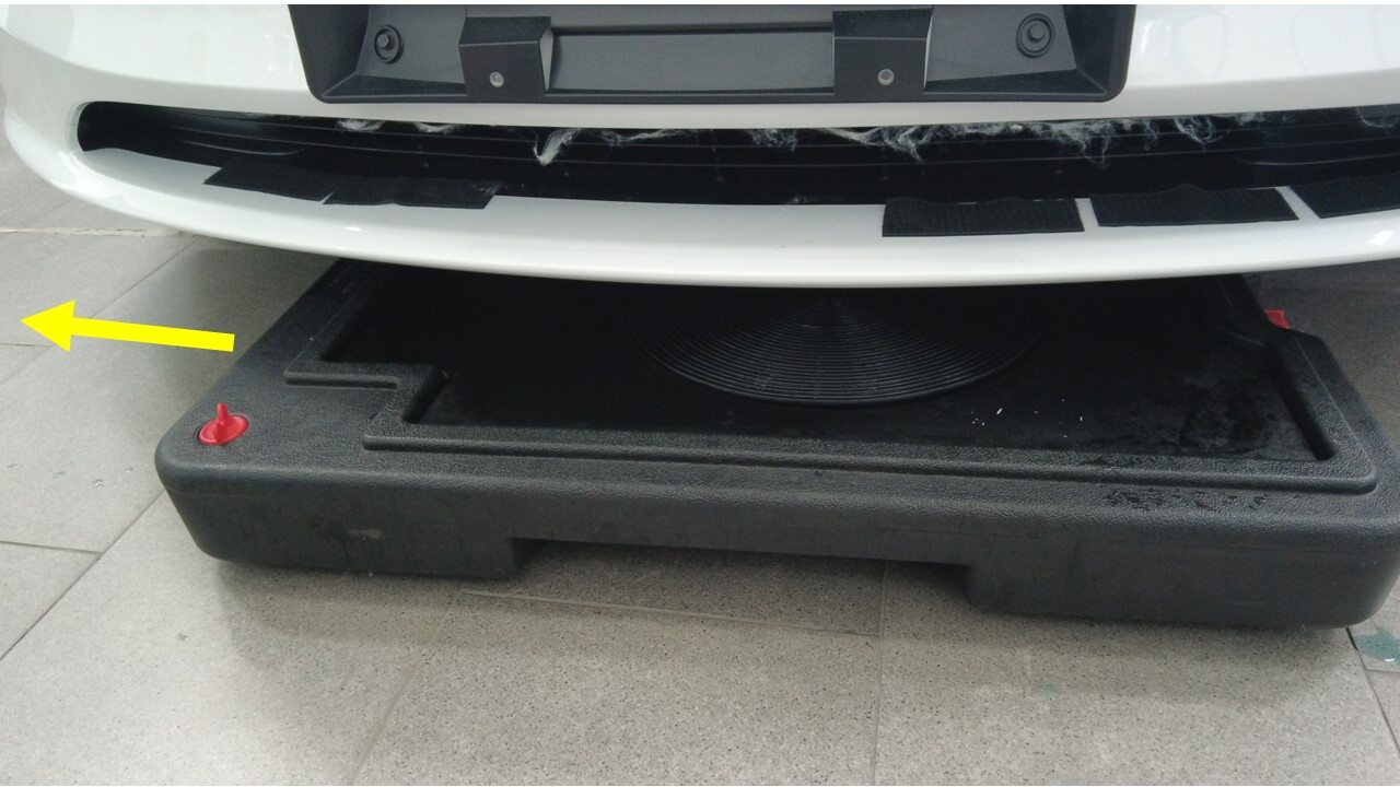
Remove fluid catcher from underneath
vehicle
-
Secure clips securing harness behind
LH shock tower
注4x clips
-
Install bolts securing front harness
bracke from vehicle
注2x bolts,10mm,9 Nm
-
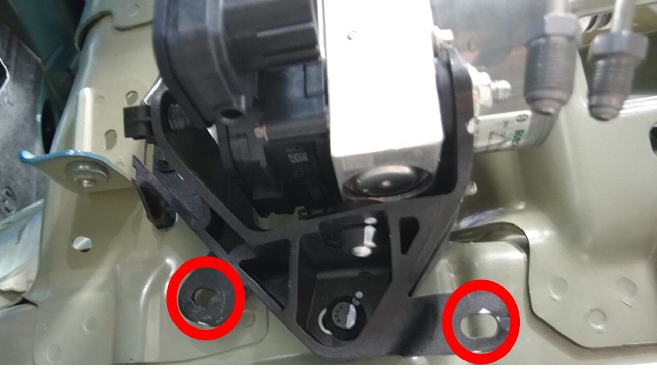
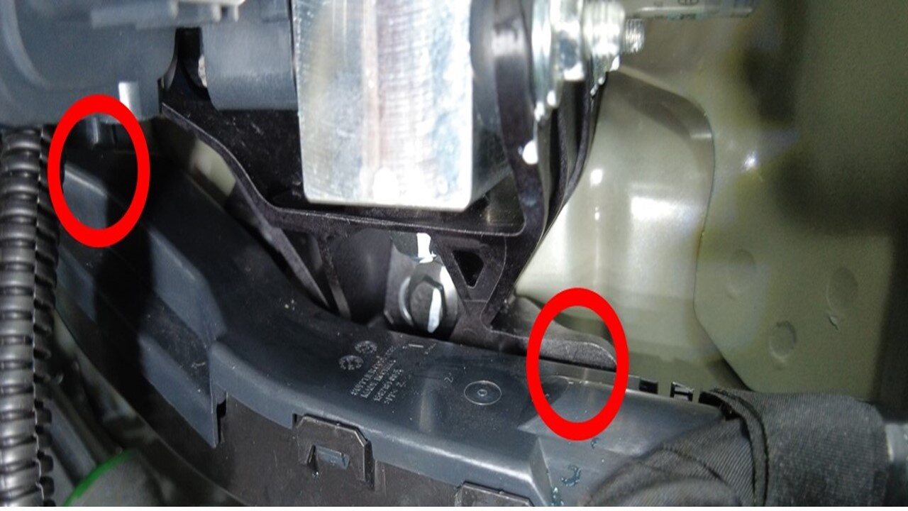
Secure LH harness bracke clips to
vehicle
注2x clips
-
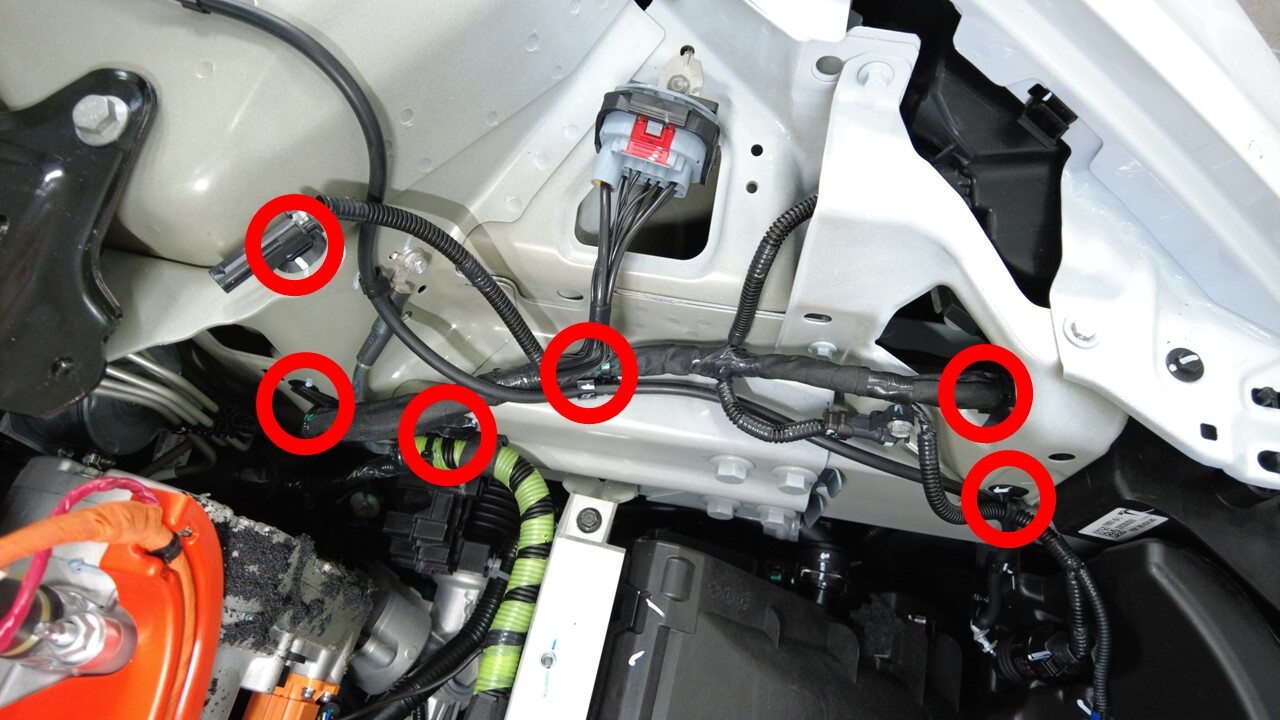
Secure front harness clips around LH
front frame rail area
注6x clips
-
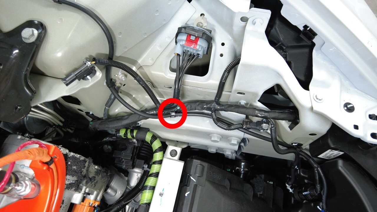
Secure washer hose to LH front frame
rail area
注1x clip
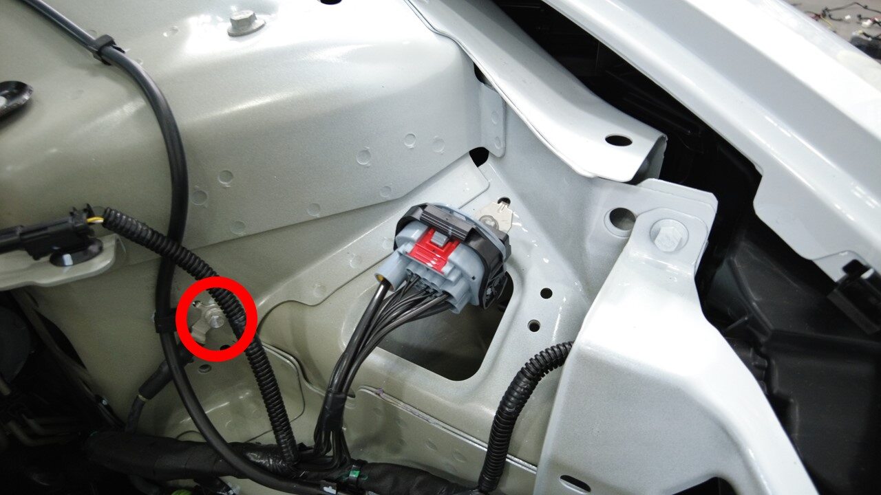
-
Install bolts securing front harness
ground terminal at LH front shock tower
注1x bolts, 10mm, 8 Nm,
-
Connect FDU front subframe
harness
注1x connector
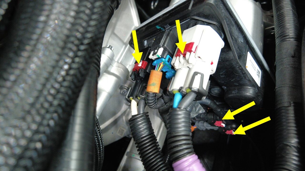
-
Connect steering gear assembly
connectors
注4x connectors
- Install the front body controller. See 3 代前控制器总成 ((拆卸和更换)).
- Install the shock tower brace. See 减震塔支架总成 ((拆卸和更换)).
- Install the LV battery. See 16V 锂离子电池包 ((拆卸和更换)).
- Install the fresh air intake assembly. See HVAC,新鲜空气进气口 ((拆卸和更换)).
- Install the wiper module. See Wiper Module (RHD) ((拆卸和更换)).
- Install the steering column. See Steering Rack (Dual Motor) (RHD) ((拆卸和更换)).
-
进行道路测试,期间进行多次急刹,确保制动踏板触感及刹车性能正常。
注将试驾校正代码 00040100 作为一项单独的工项添加至“服务工单”中。


