31/01/2024 18:32:44
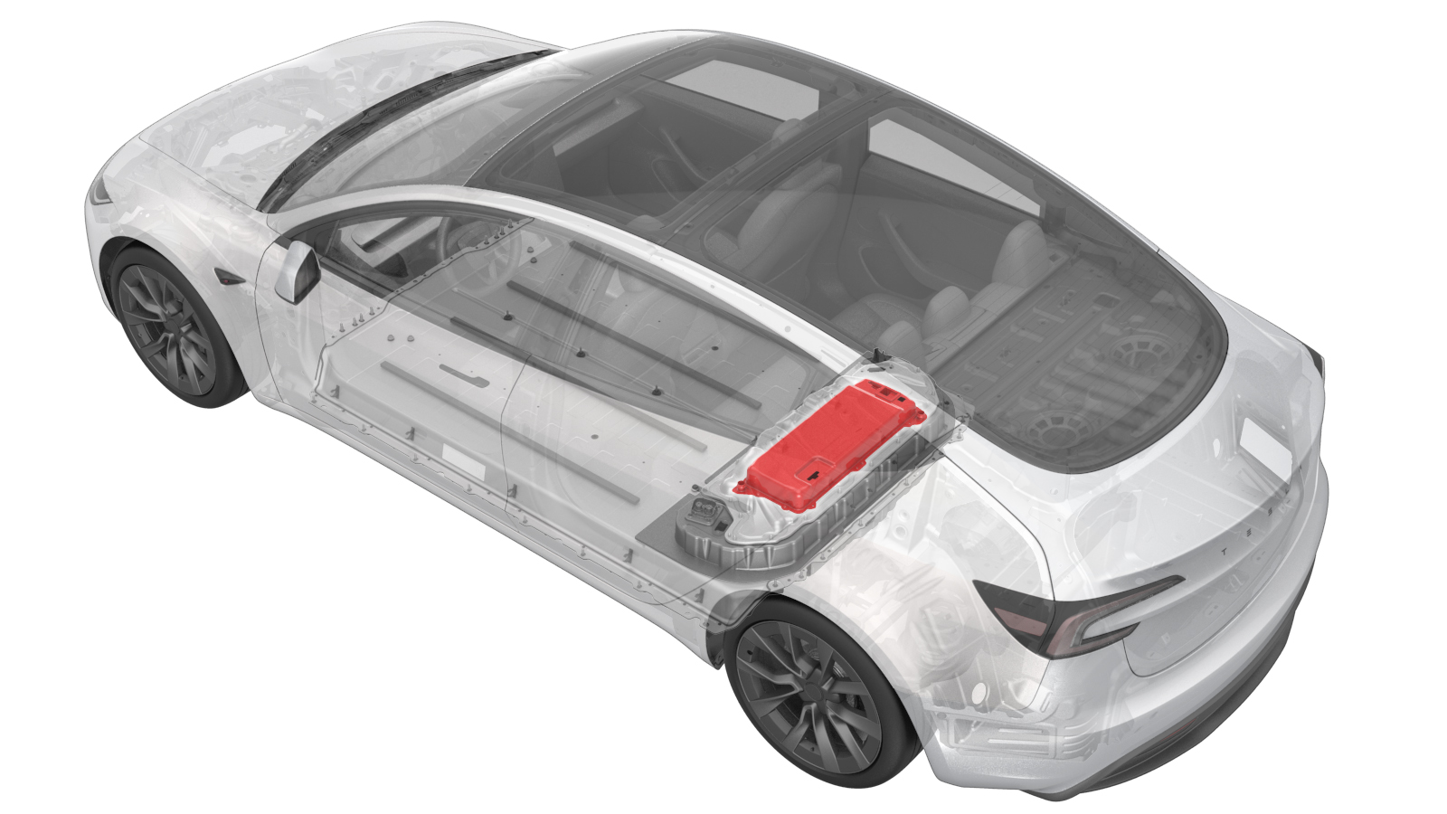
PCS 总成 ((拆卸和更换))
 校正代码
1630010252
FRT
2.16
注意:除非本程序中另有明确规定,否则上述校正代码和 FRT 反映的是执行本程序(包括关联程序)所需的所有工作。除非明确要求,否则请勿堆叠校正代码。
注意:请参阅平均维修工时,深入了解 FRT 及其创建方式。要提供有关 FRT 值的反馈,请发送电子邮件至LaborTimeFeedback@tesla.com。
注意:请参阅人员保护,确保在执行以下程序时穿戴适当的个人防护装备 (PPE)。
校正代码
1630010252
FRT
2.16
注意:除非本程序中另有明确规定,否则上述校正代码和 FRT 反映的是执行本程序(包括关联程序)所需的所有工作。除非明确要求,否则请勿堆叠校正代码。
注意:请参阅平均维修工时,深入了解 FRT 及其创建方式。要提供有关 FRT 值的反馈,请发送电子邮件至LaborTimeFeedback@tesla.com。
注意:请参阅人员保护,确保在执行以下程序时穿戴适当的个人防护装备 (PPE)。
警告
尽管此程序已经过验证,但仍是一个草案。可能没有警告和注意事项。请遵守安全要求,处理或靠近高压系统和部件时,请谨慎操作。请将校正修理内容及反馈发送至ServiceDevelopment@teslamotors.com。
拆卸
-
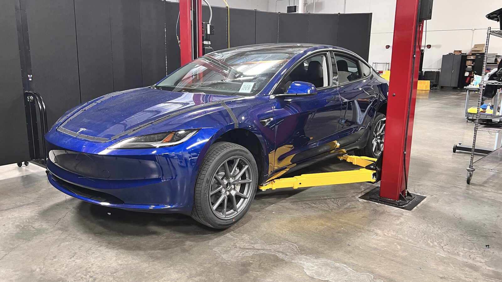
Raise and support vehicle
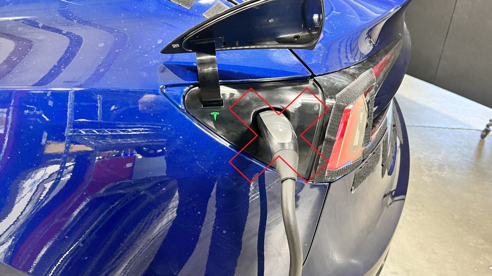
注Ensure vehicle is not charging
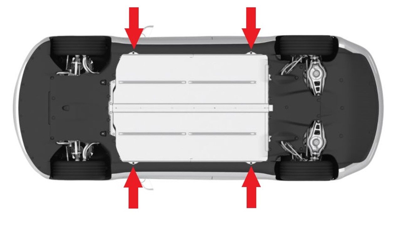
-
Open all four doors
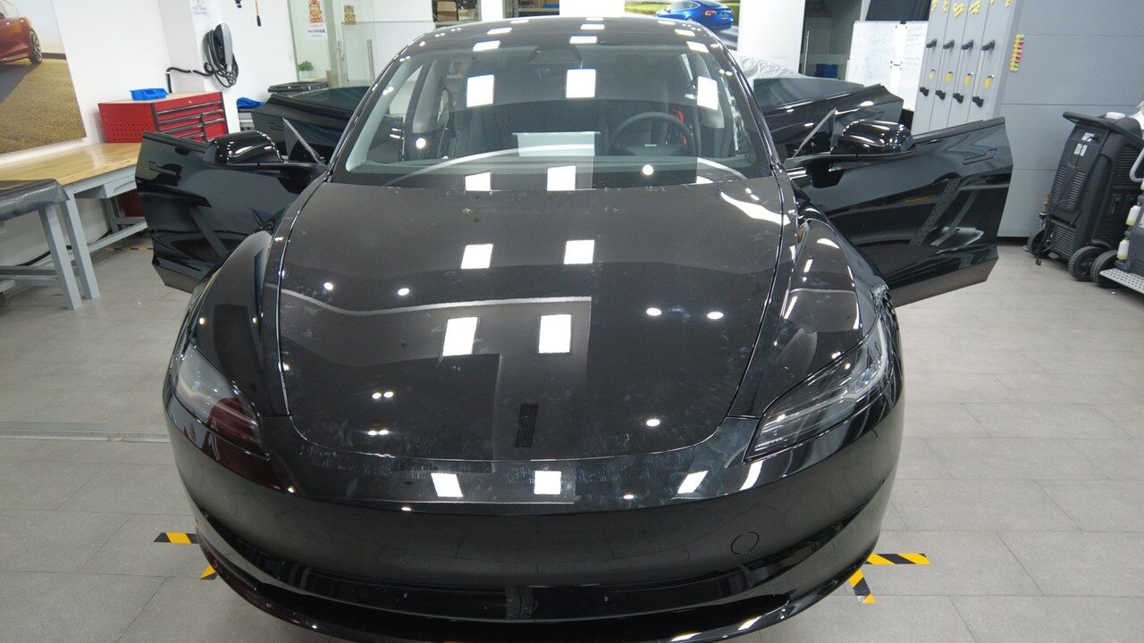
-
Lower all four windows
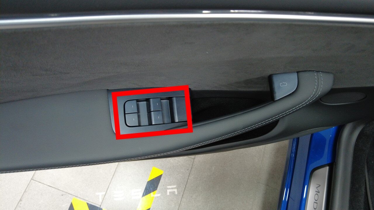
-
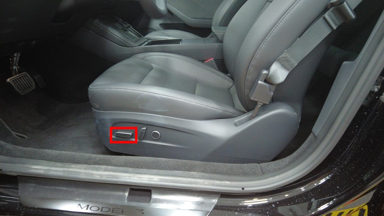
Move LH front seat forward
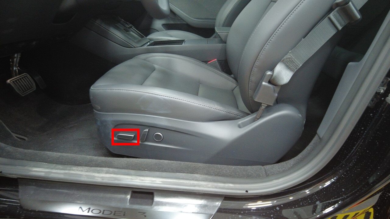
-
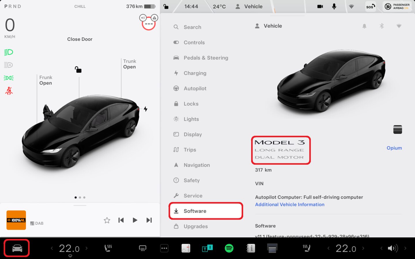
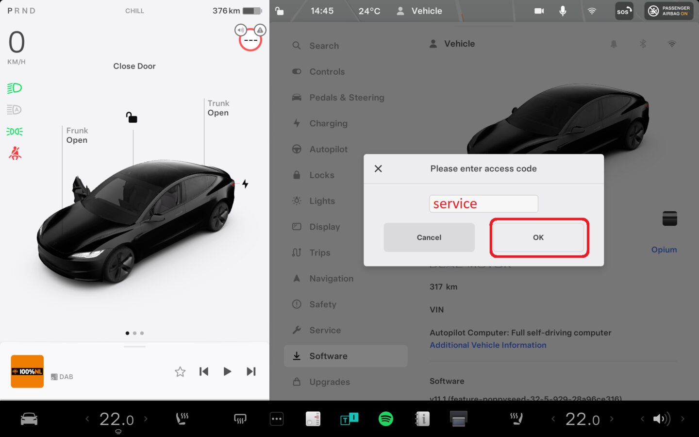
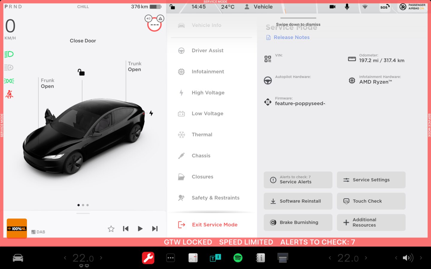
Place vehicle in service mode
注Via UI > Controls > Software, Touch and hold "Model 3" for 4 seconds then release, Use screen keyboard to type "service" into dialog box then select OK
-
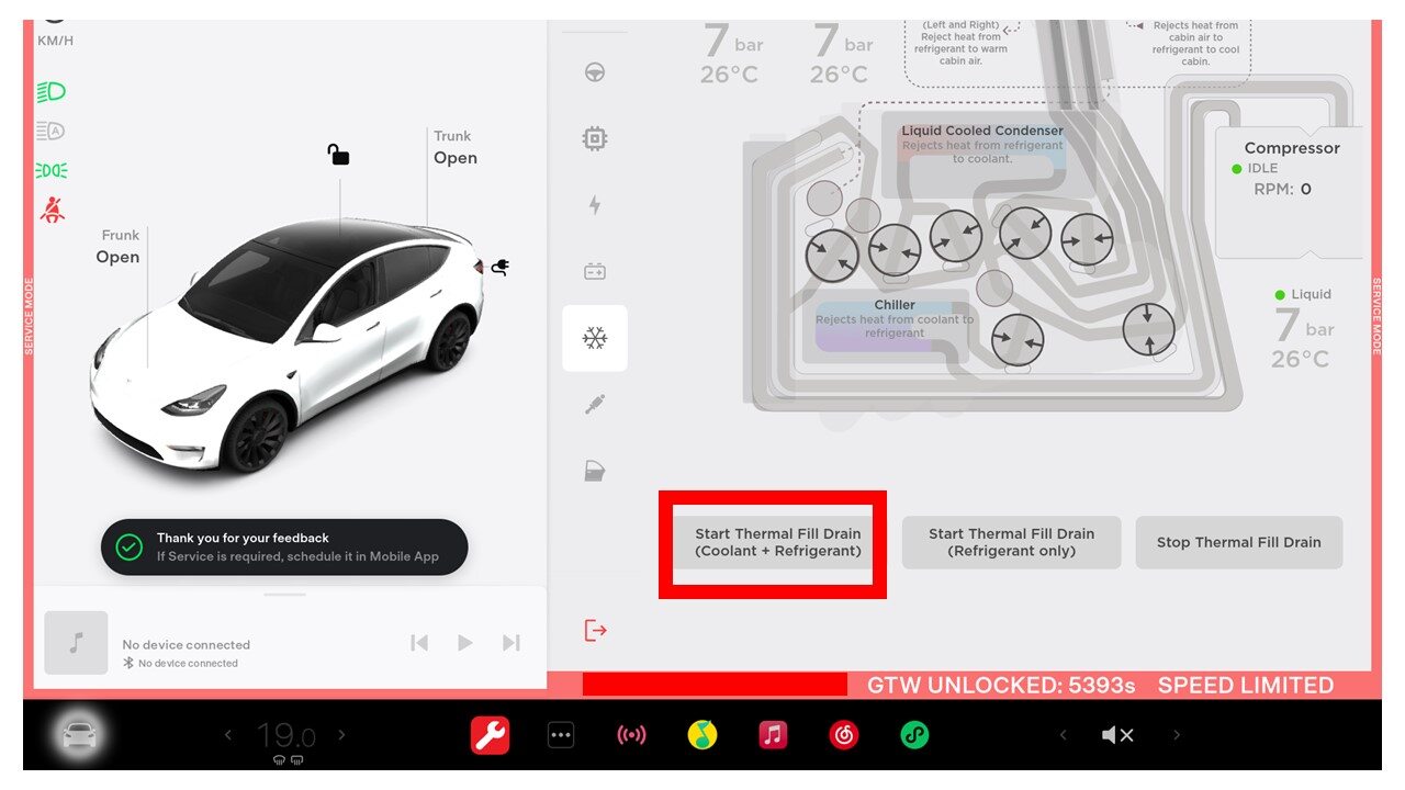
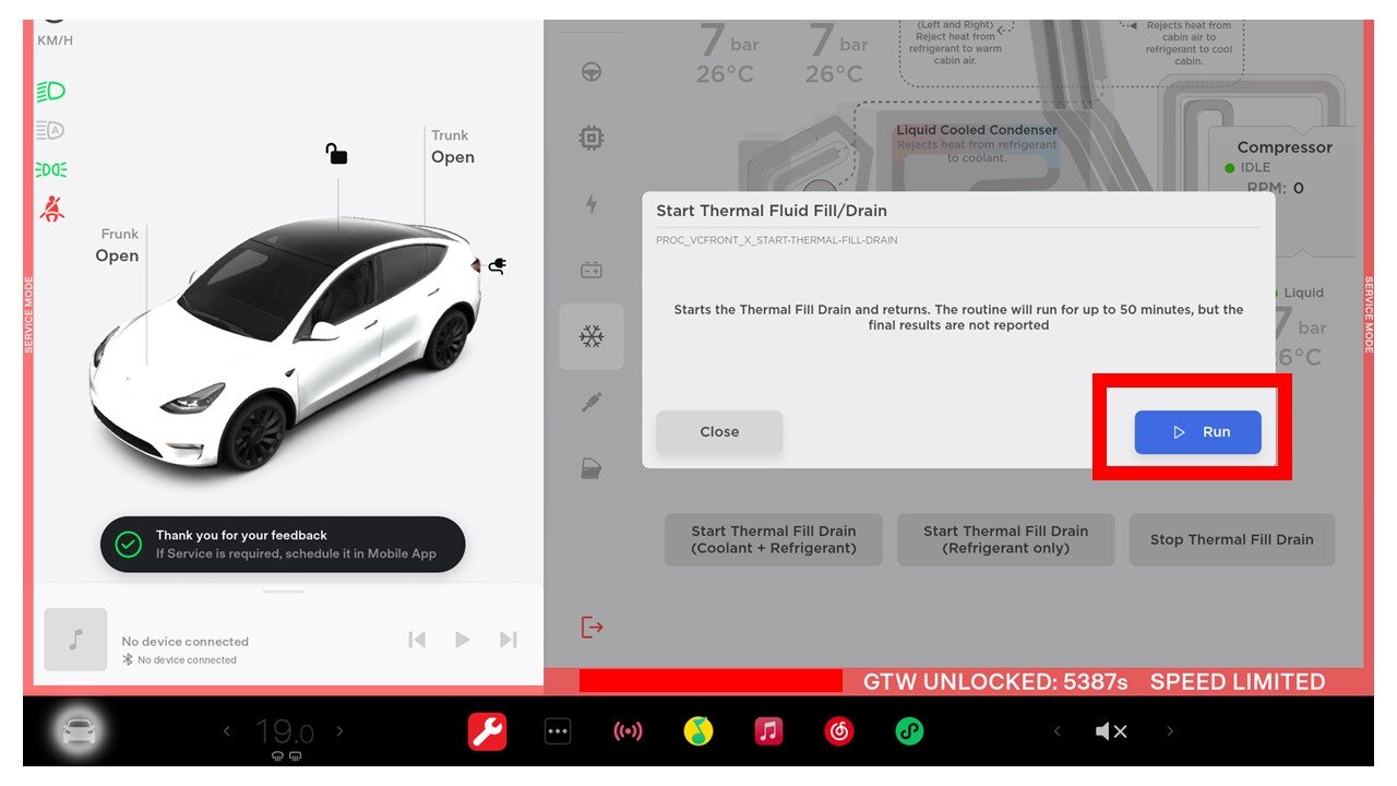
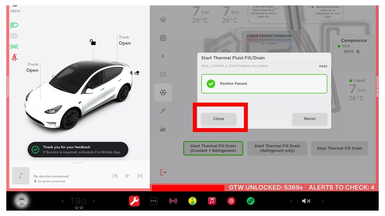
Run Thermal Fill Drain (Coolant +
Refrigerant) through the UI
注Select Thermal > Refrigerant System > Start Thermal Fill Drain (Coolant + Refrigerant), Click Run, Close once routine is completed

-
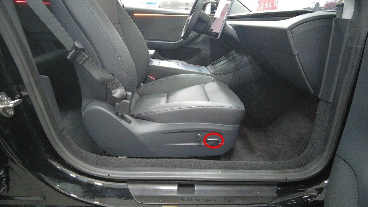
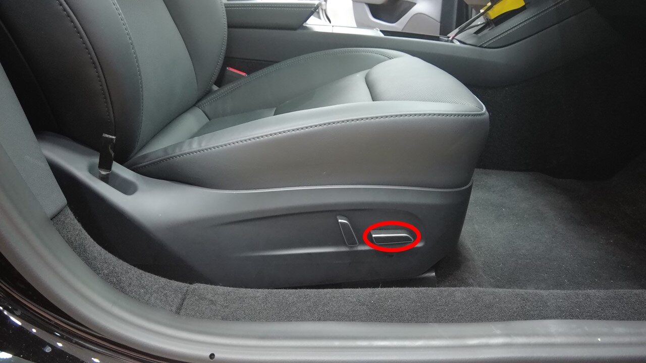
Move RH front seat forward
-
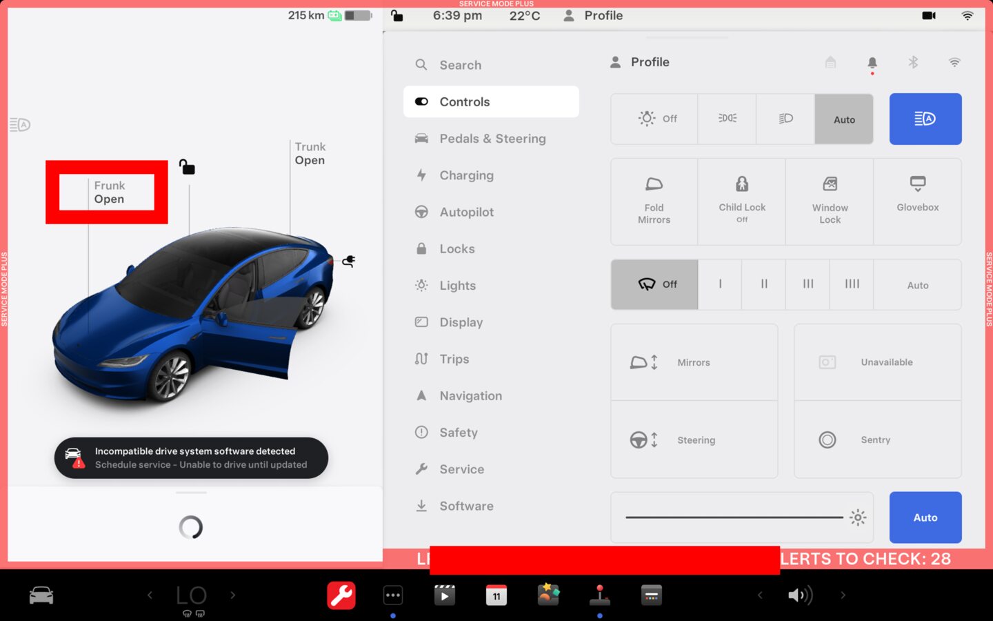
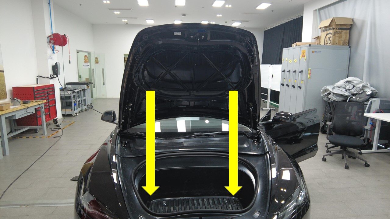
Open hood

-
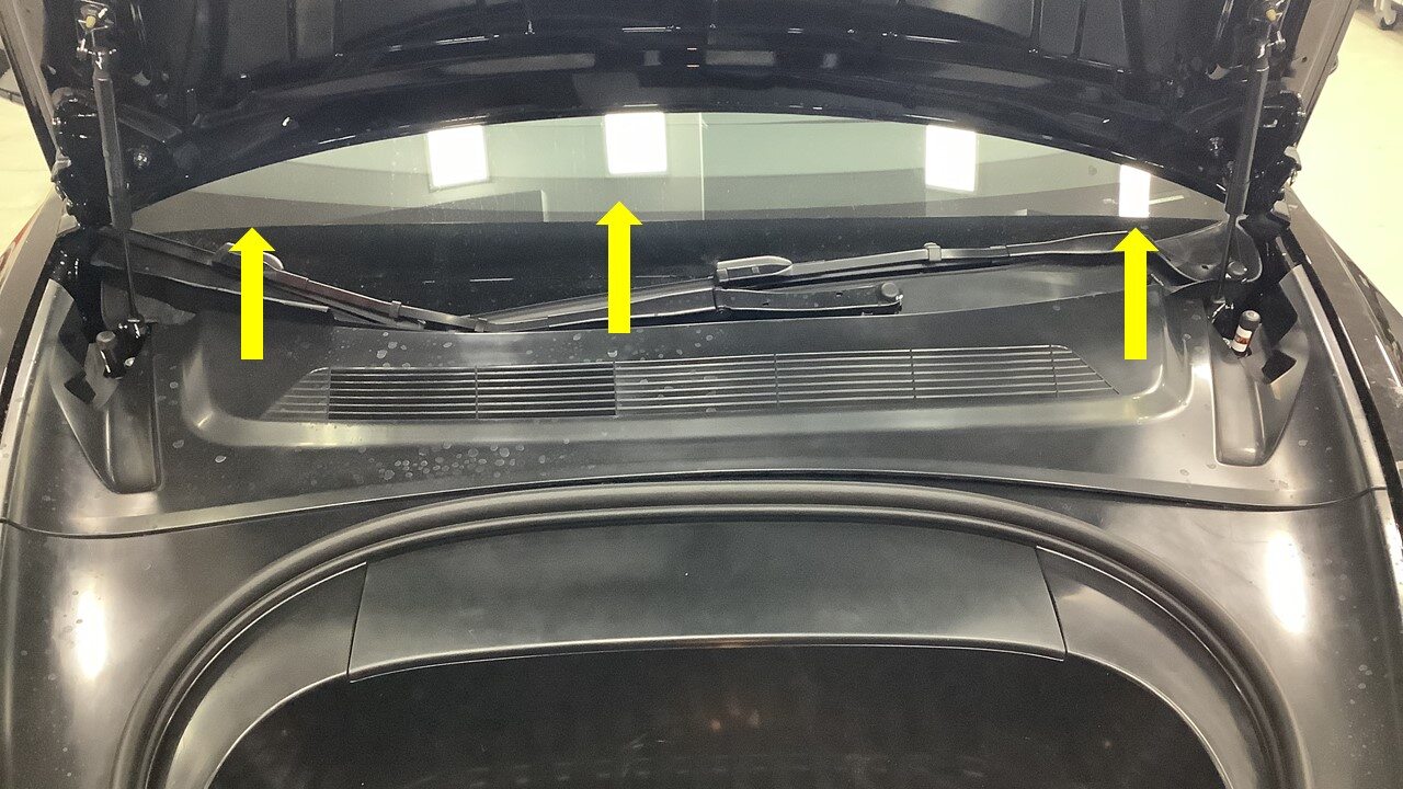
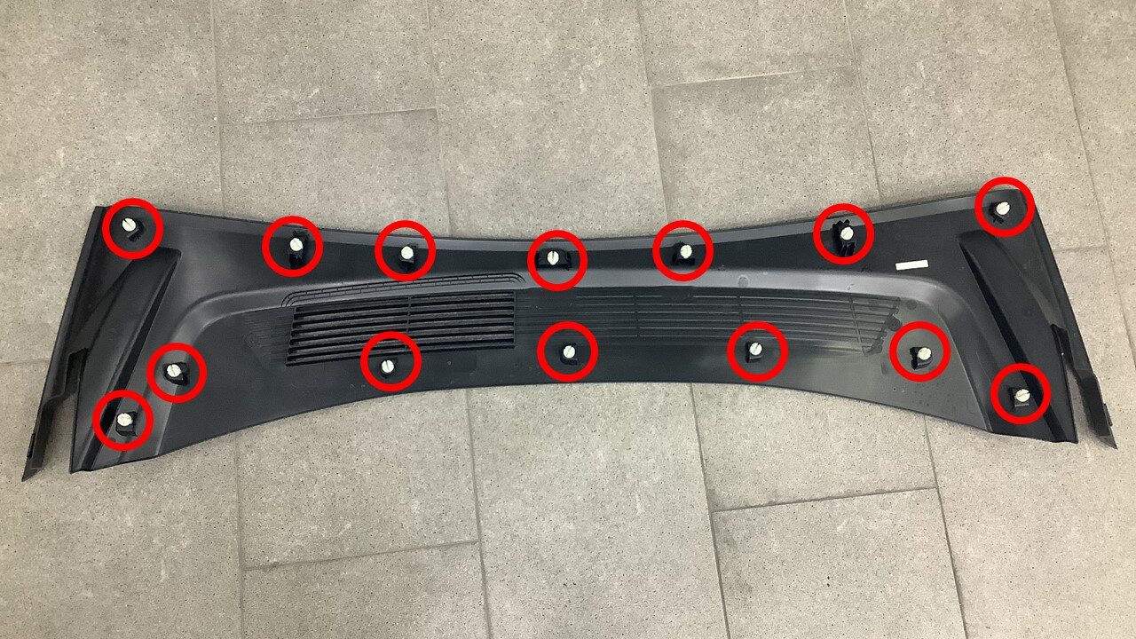
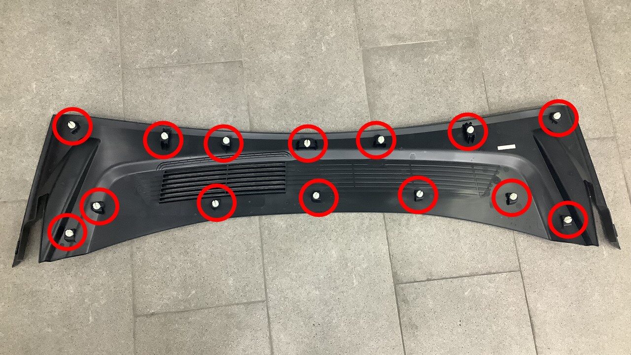
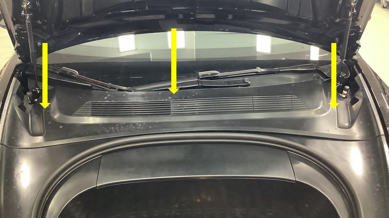
Remove rear underhood apron
注14x clips
-
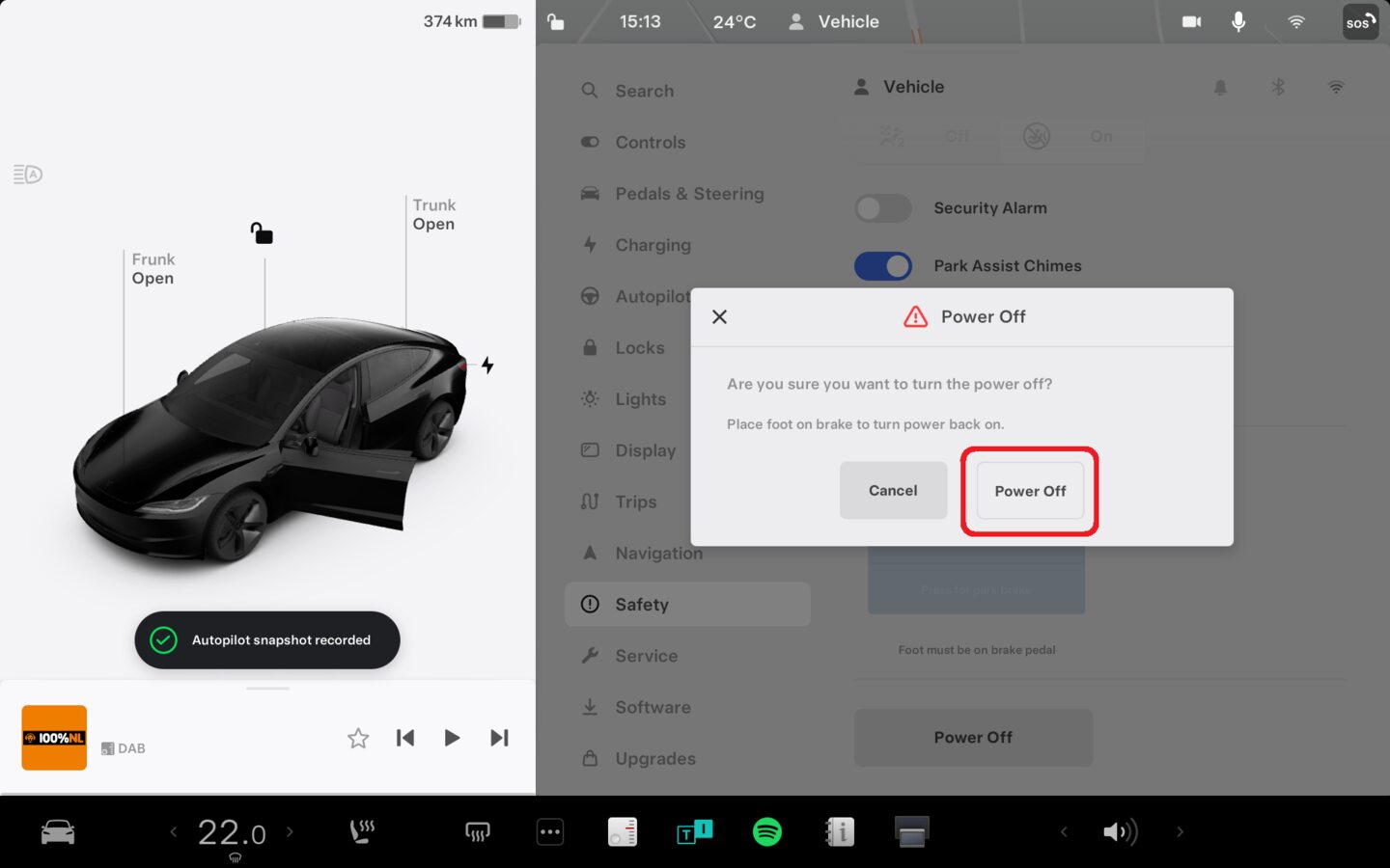
Power off vehicle from center
display
注Via Controls > Safety > Power Off, Select Power Off button at warning dialogue box

-
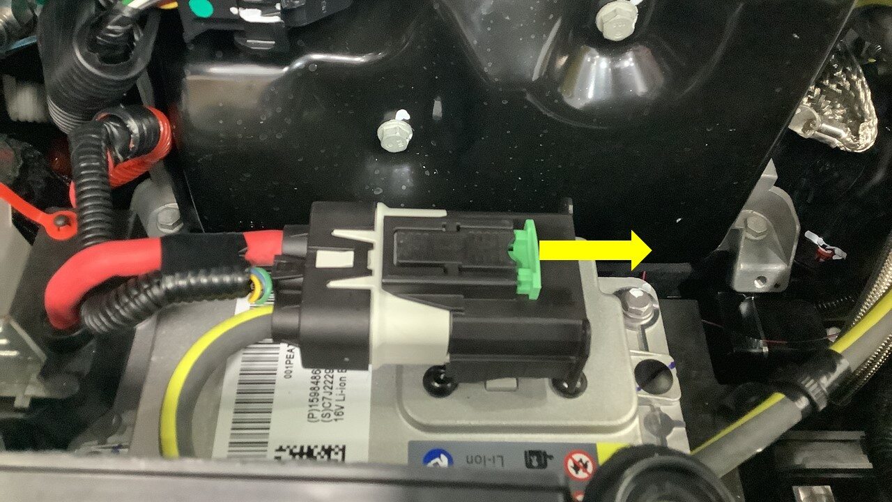
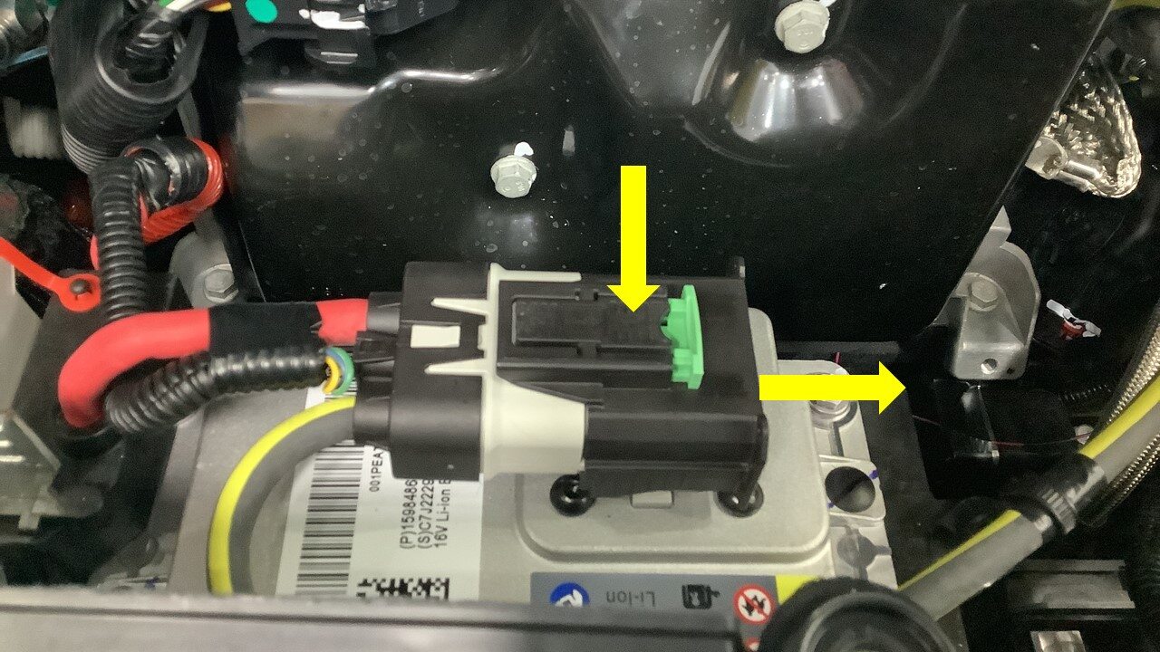
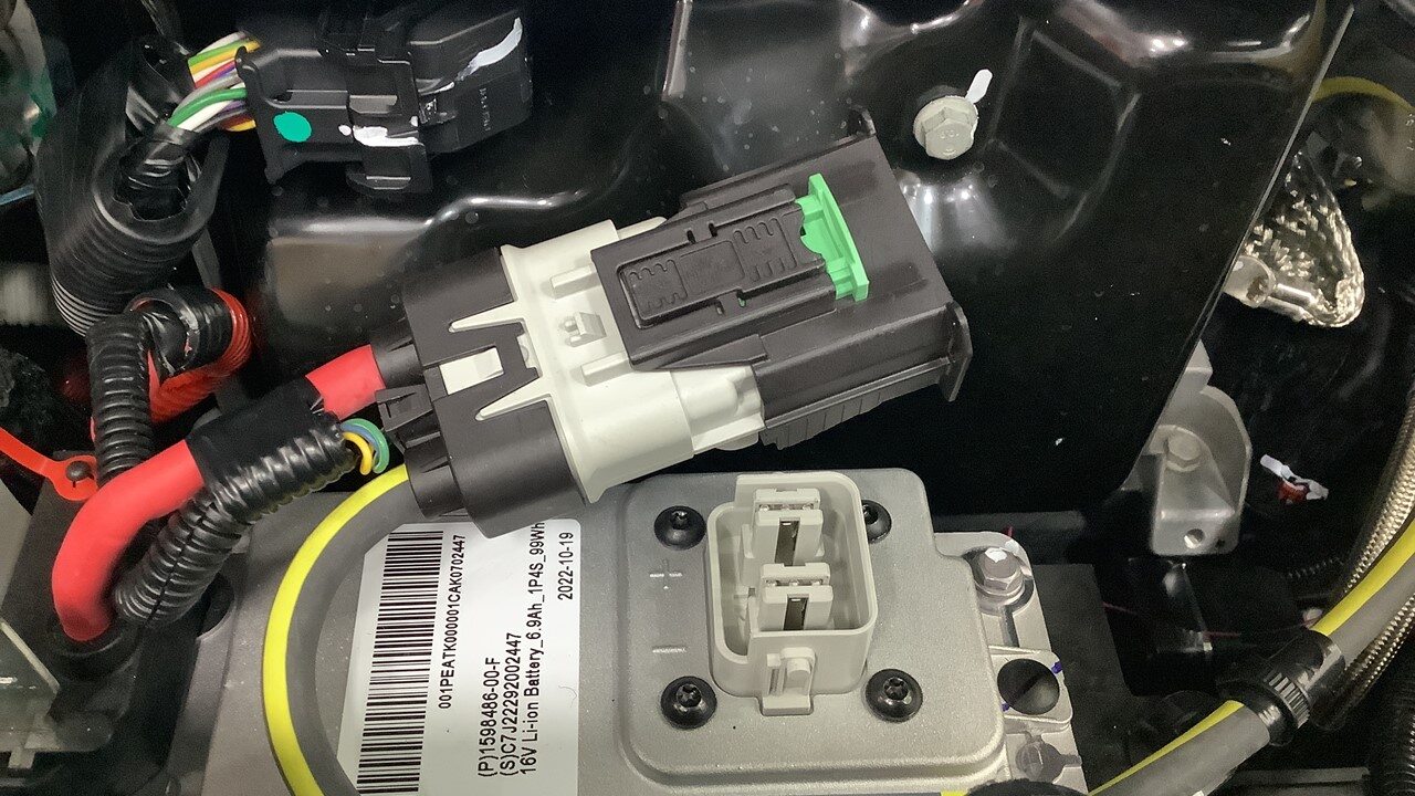
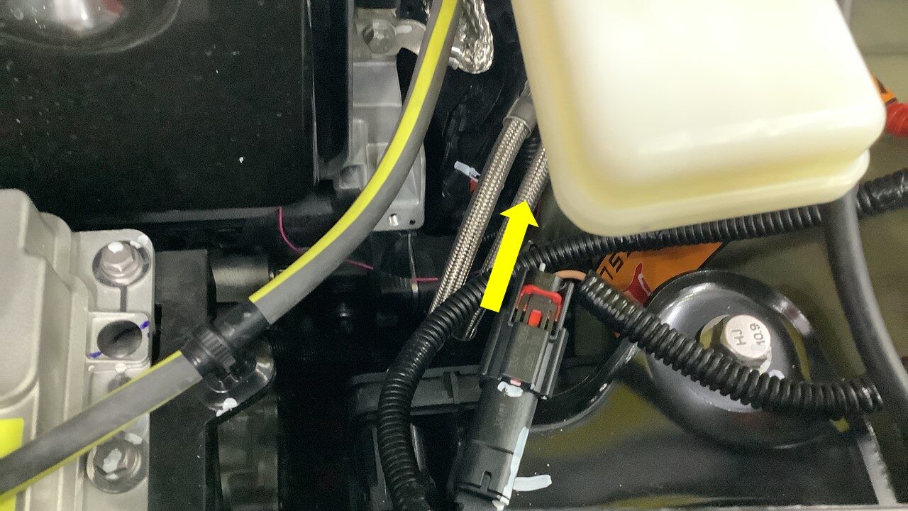
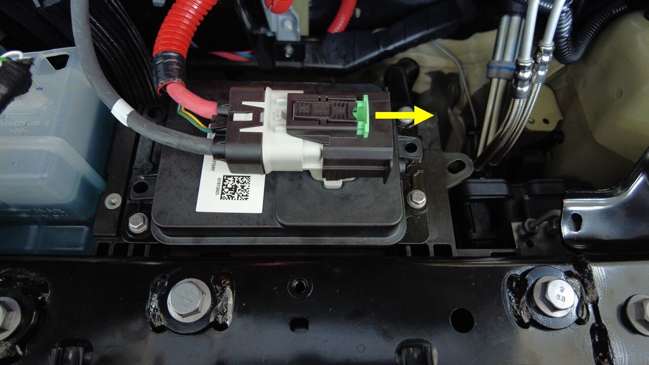
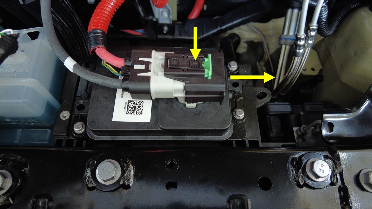
Disconnect LV battery and First
Responder Loop
注2x connectors, Release green locking tab, Press black tab then pull black connector lock outwards to release connection, Release red lock tab on FRL, Allow 2 minutes for all electrical circuits to fully discharge
-
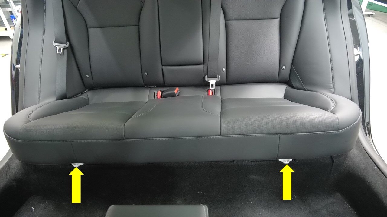
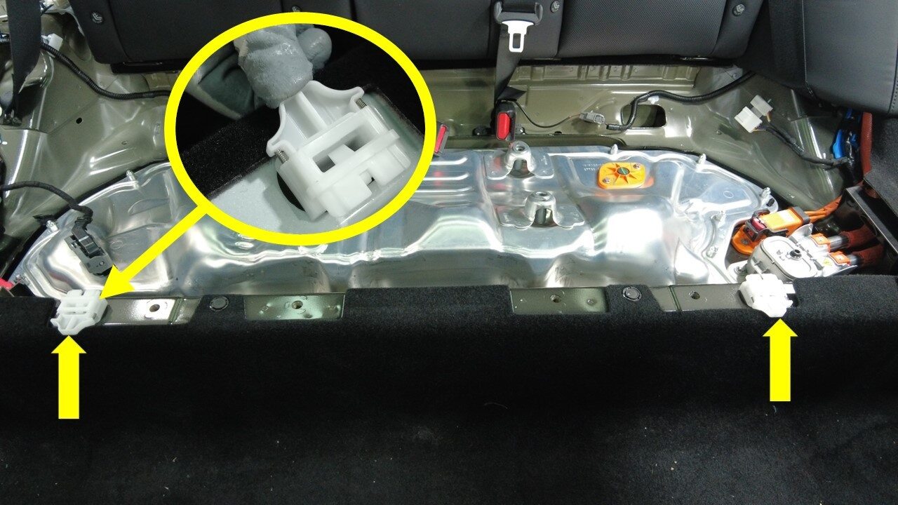
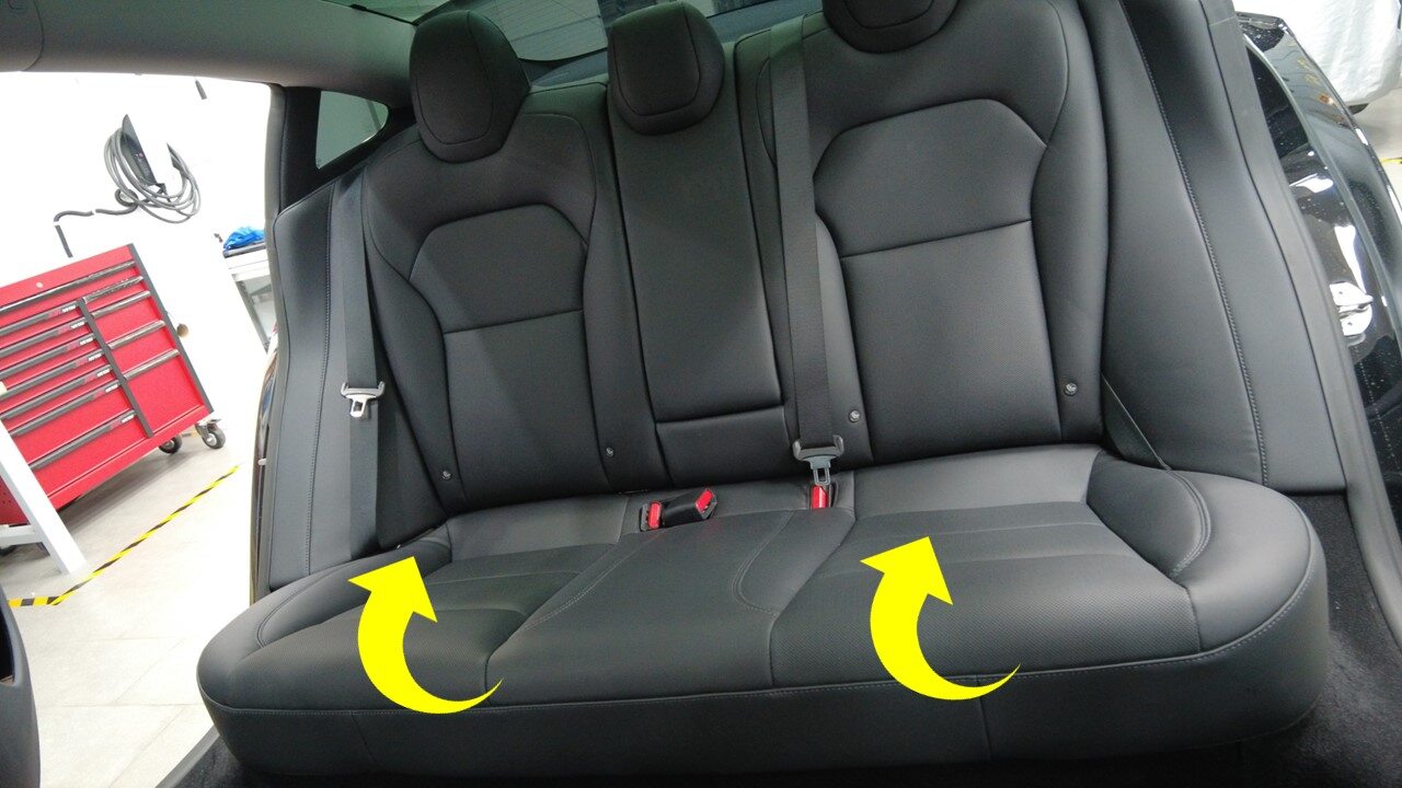
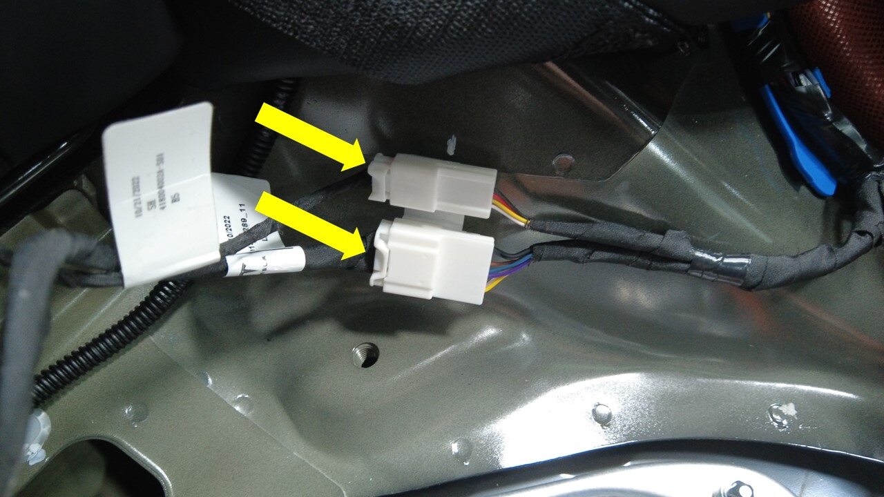
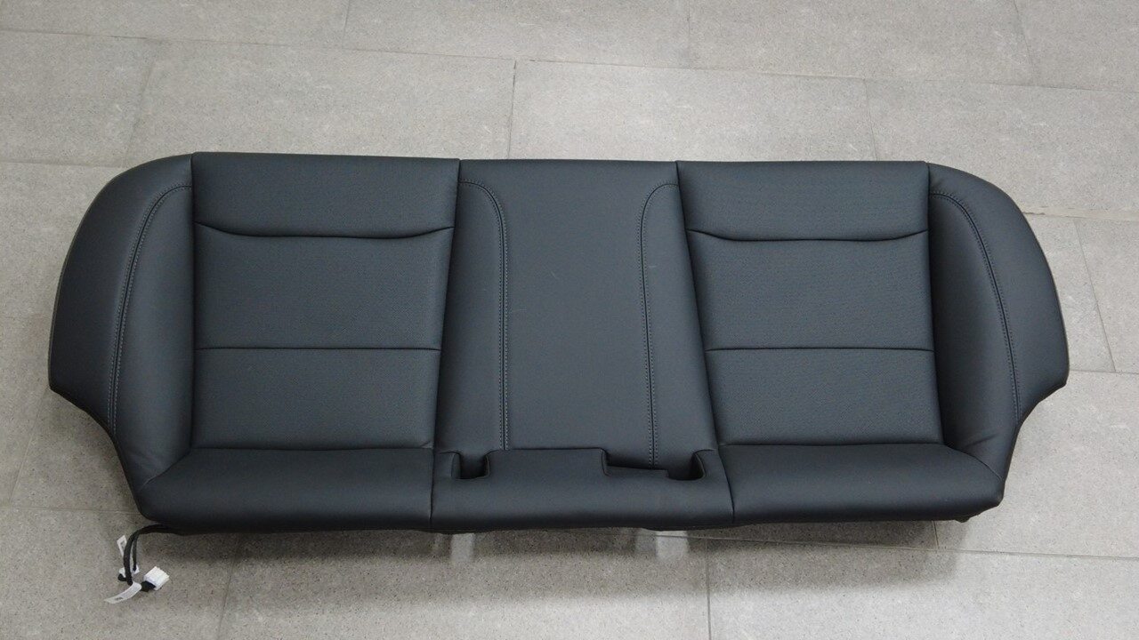
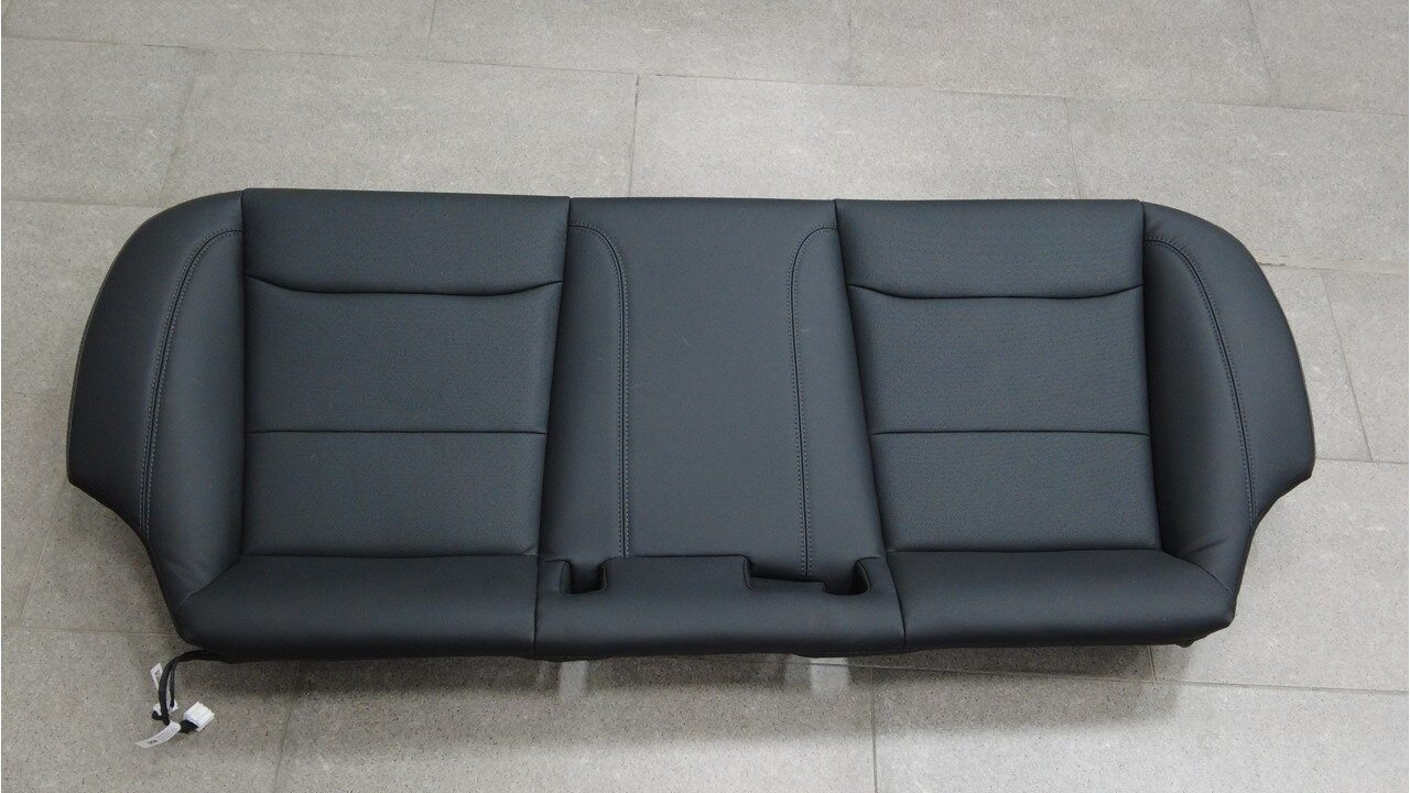
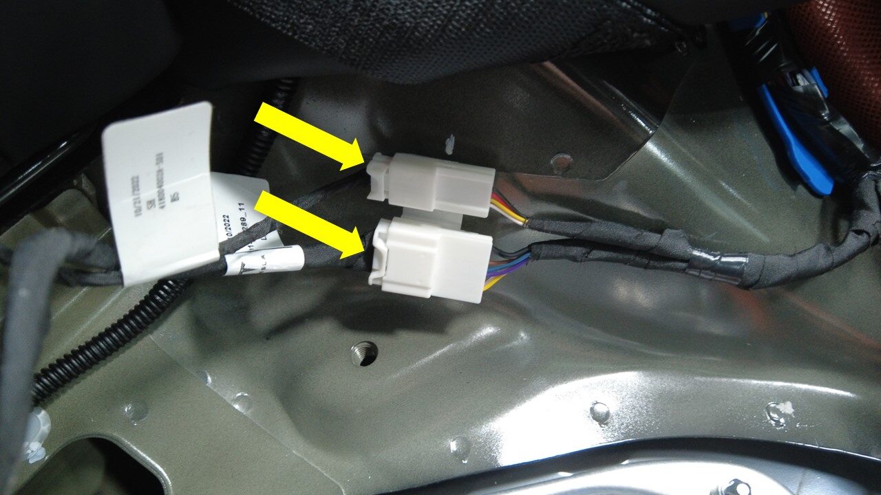
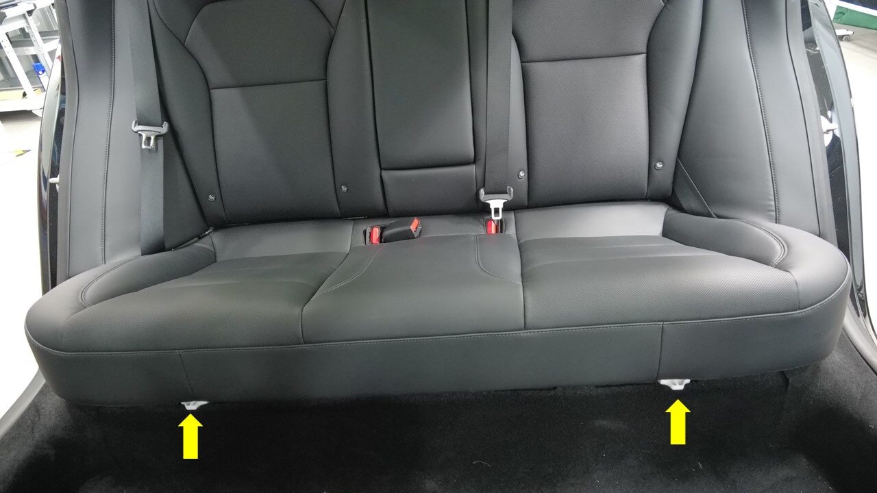
Release 2nd row seat cushion and
disconnect harness
注2x clips, 2x connectors, Press tabs backward then pull front edge up
-
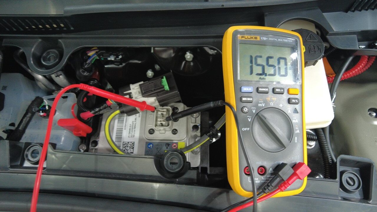
Verify operation of multimeter
注Set multimeter to DC voltage, Confirm multimeter is properly measuring voltage by testing the 16v battery
-
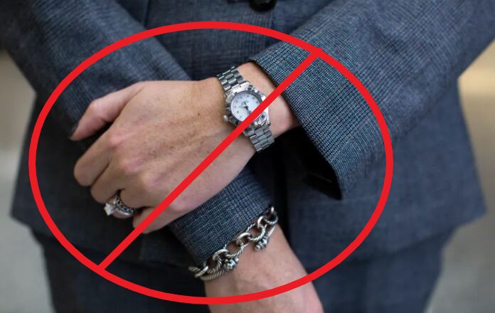
Remove all items from pockets and
ensure not wearing metal items

-
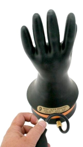
Inspect HV insulating gloves
注Check gloves for damage prior to use, Refer to service document TN-15-92-003 R1, for information on inspecting HV gloves. https://service.teslamotors.com/protected-doc/ServiceBulletins/External/TN/TN-15-92-003_High_Voltage_Awareness_Care_Points_R4.pdf
-
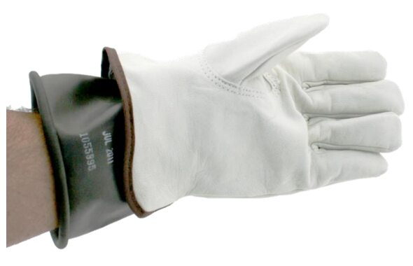
Put on HV insulating gloves and
leather over gloves
注Make sure to wear Electrical Protective Gloves any time Hioki tester is used
-
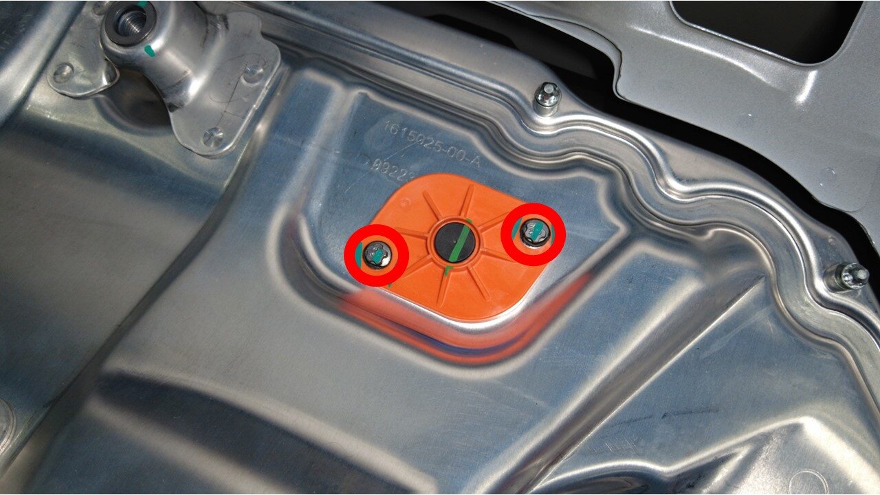
Remove bolts securing the ancillary
bay probe lid cover to the ancillary bay cover
注2x bolts, EP10 5-Lobe, 6 Nm, Discard after removal
-
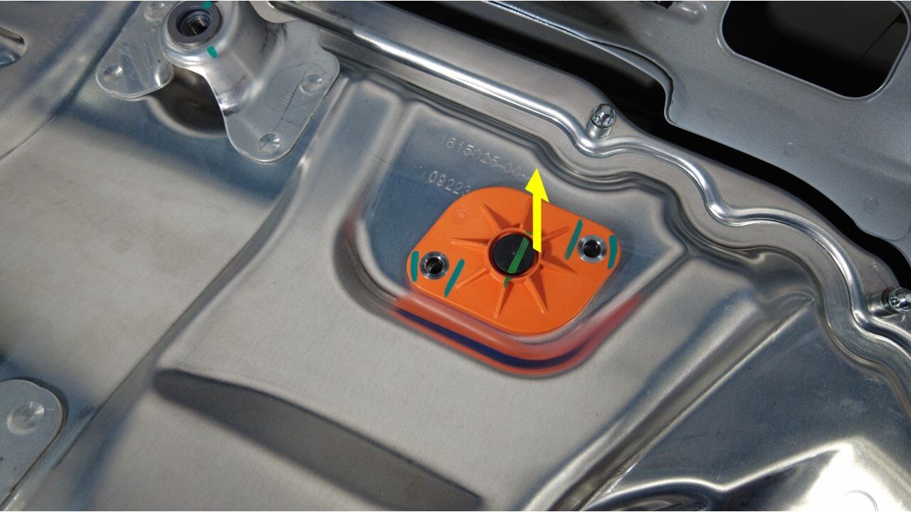
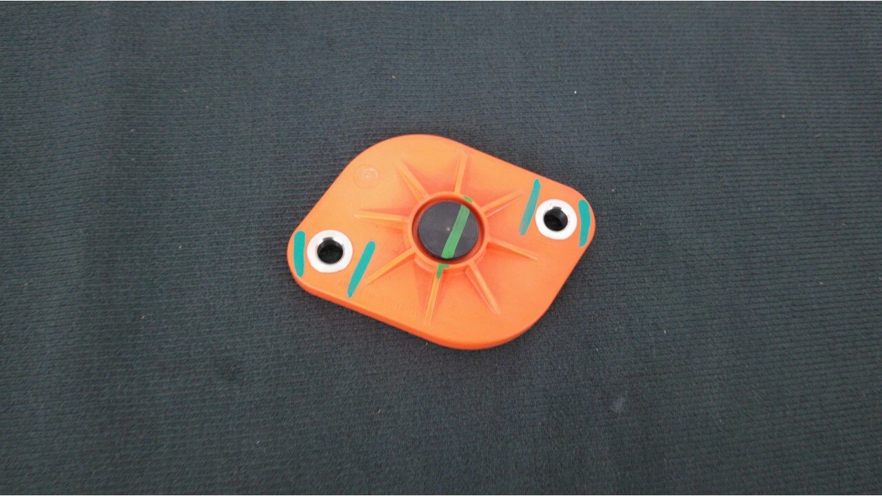
Remove the ancillary bay probe lid
cover from the ancillary bay cover
-
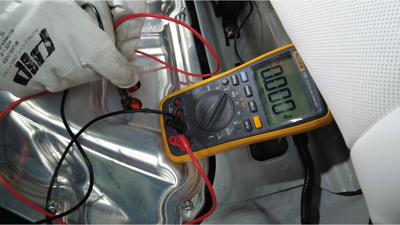
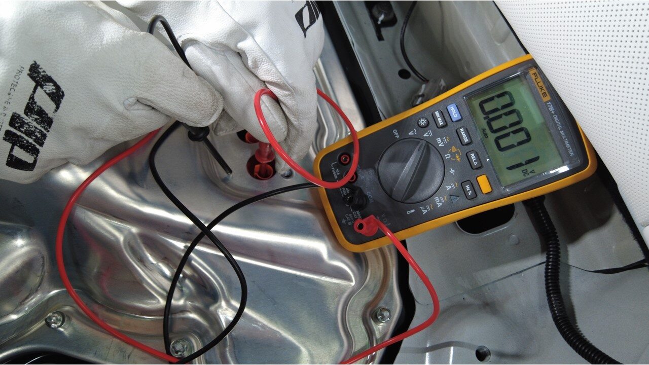
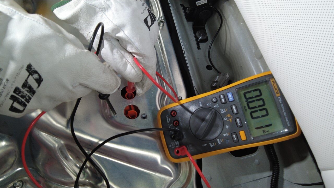
Verify no high voltage
注Make sure to wear PPE (HV gloves, safety glasses) when working on high voltage component, If voltage is greater than 10V, Pack contactors are not open or welded, Stop work and reach out to Service Engineering
-
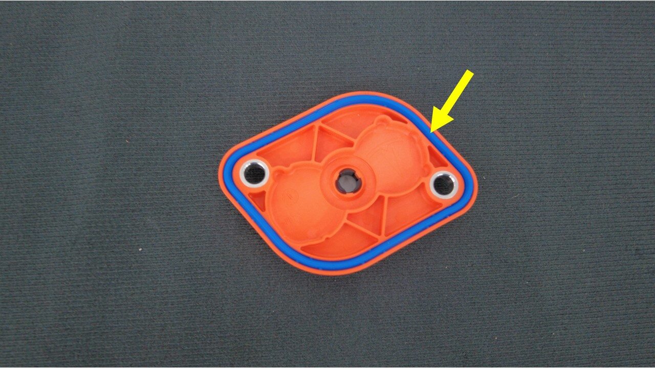
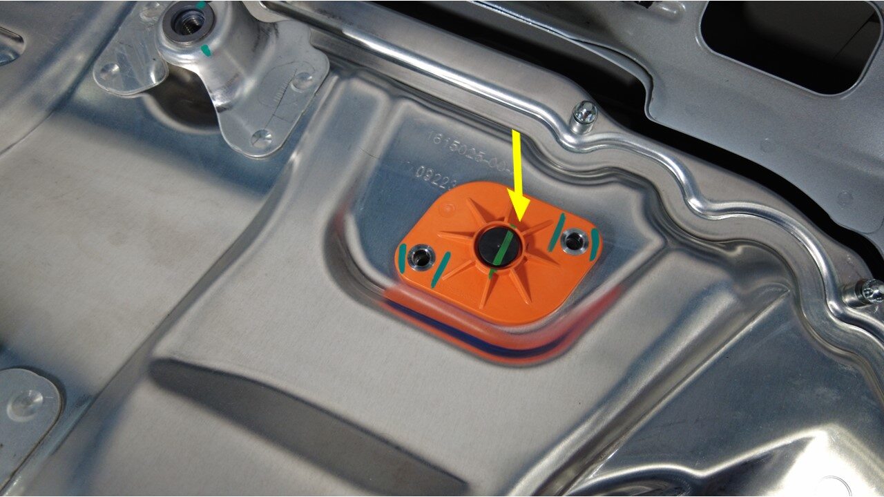
Inspect the ancillary bay probe lid
cover gasket then position onto the ancillary bay cover
注Confirm no visual damage present,Wipe the ancillary bay with IPA to clean surface,Allow to 1 minute dry time
-
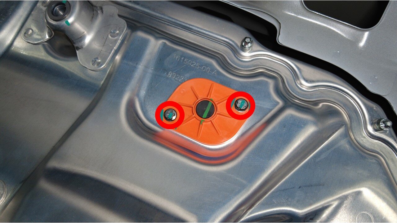
Install bolts securing the ancillary
bay probe lid cover to the ancillary bay cover
注2x bolts, E10 5-Lobe, 6 Nm, Install new fasteners
-
Remove HV insulating gloves

-
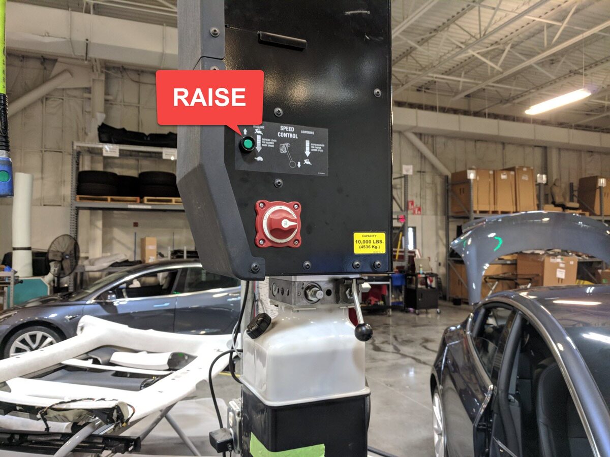
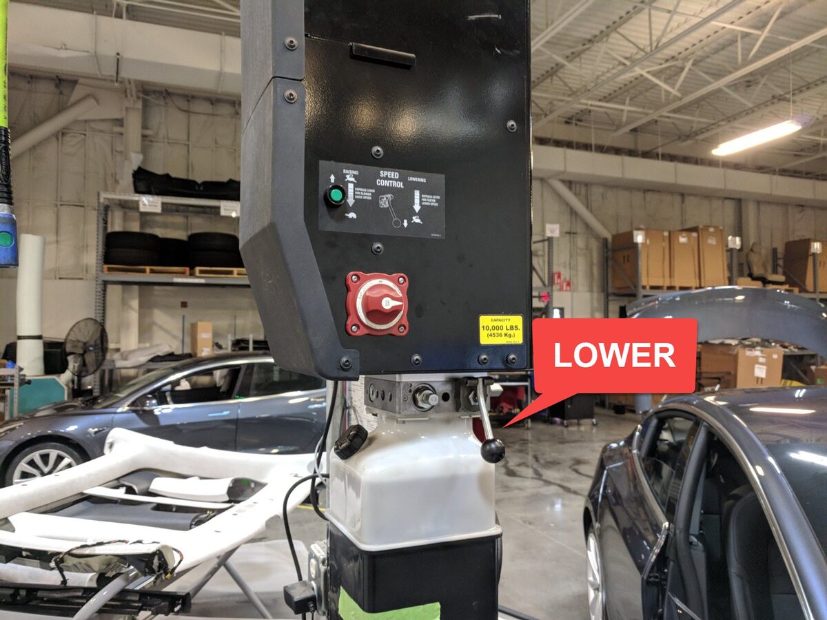
Raise vehicle fully and lower lift
onto locks
注Set vehicle to comfortable working height, Make sure there's an audible click of the locks on both sides before lowering, otherwise vehicle may tilt to the side, Verify doors are clear of surrounding objects
-
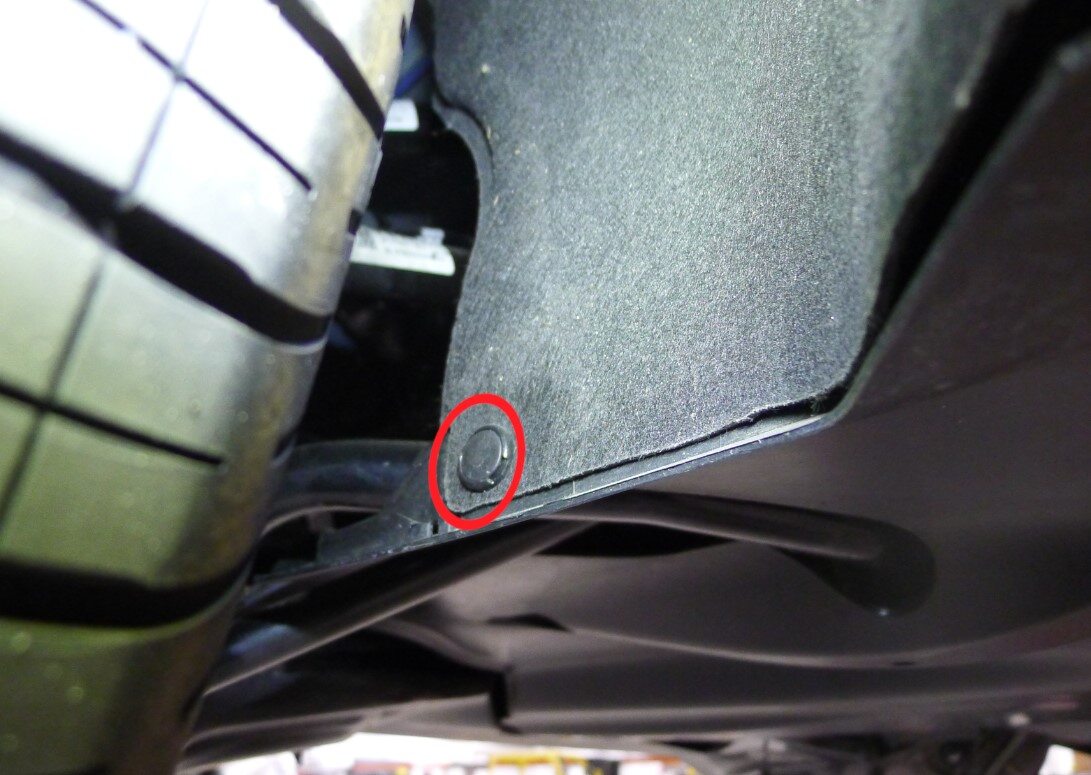
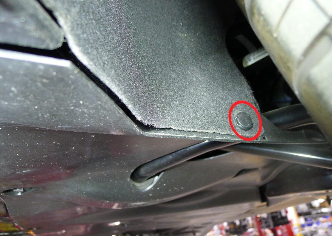
Remove LH and RH clips securing rear
aero shield to wheel house liner
注2x clips
-
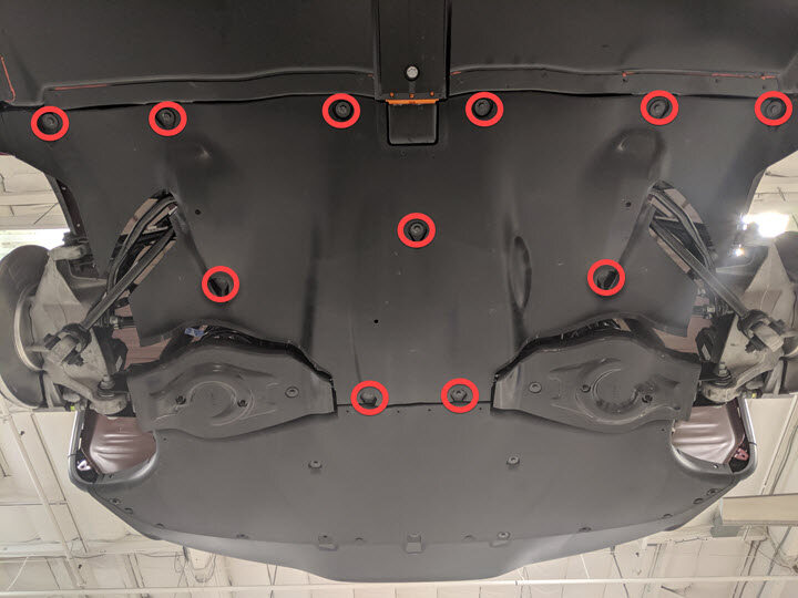
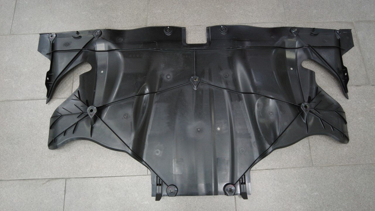
Remove rear aero shield
注11x bolts, 10mm, 5 Nm
-
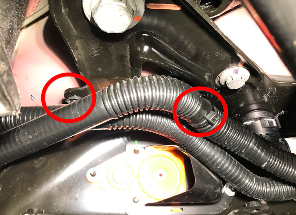
Release clips securing coolant hoses
to LH shear plate
注2x fir tree clips
-
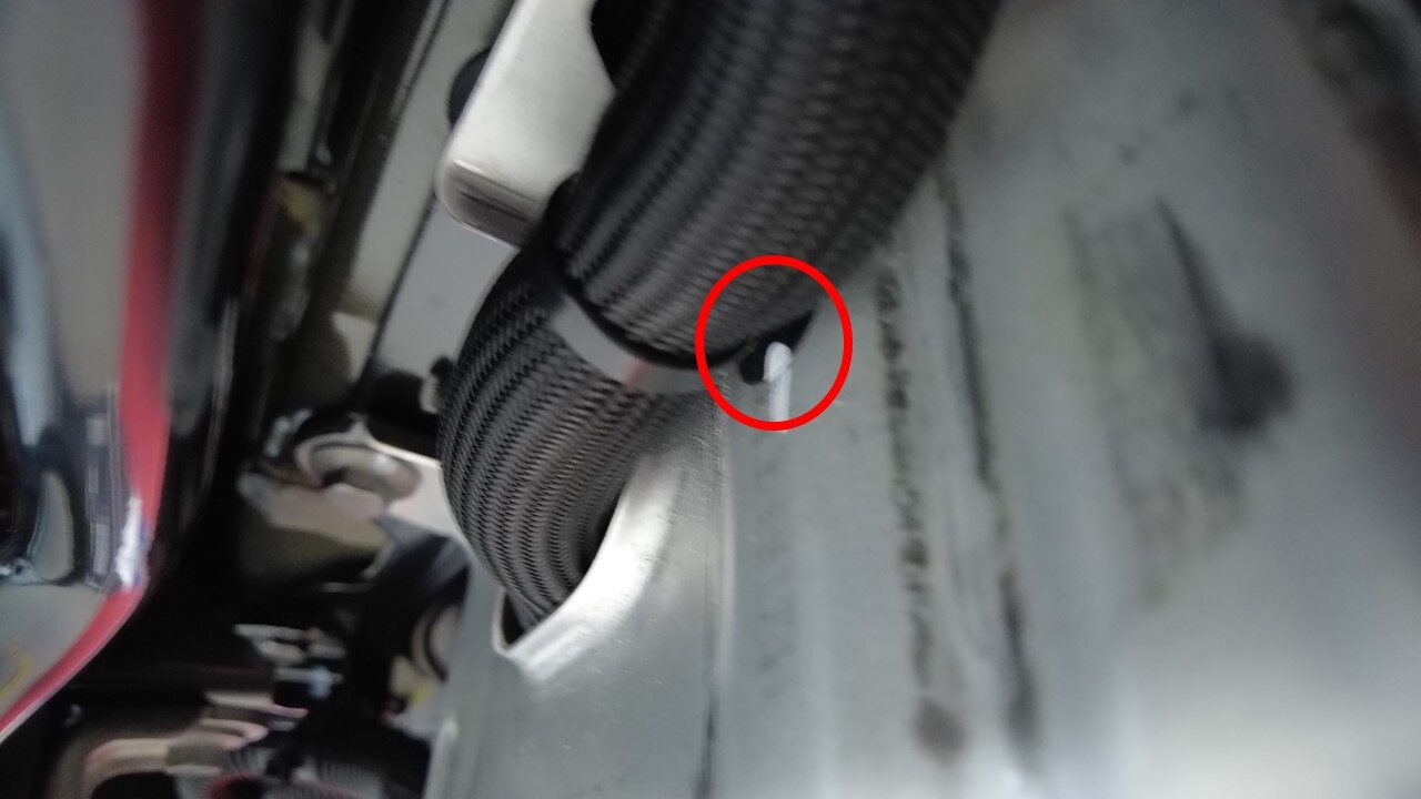
Release LH side hose clip from rear
battery skid plate enclosure
注1x fir tree clip
-
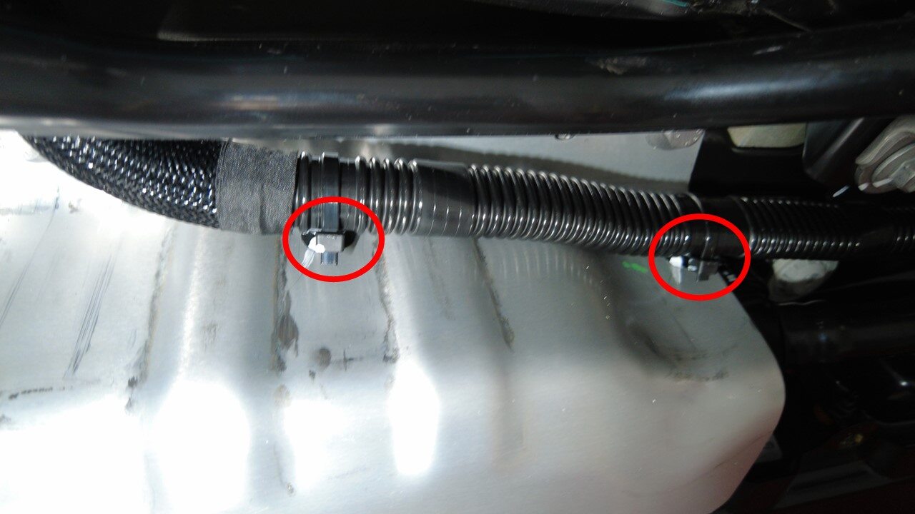
Release RH side hose clips from rear
battery skid plate enclosure
注2x fir tree clips
-
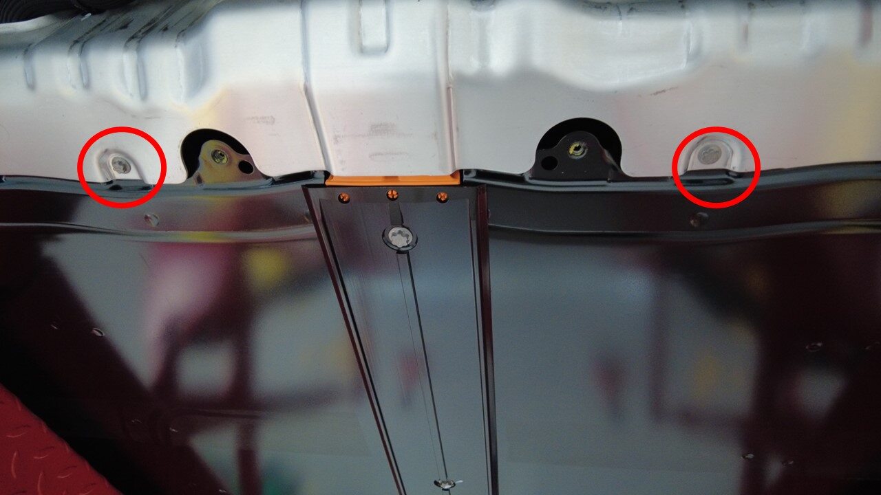
Remove lower bolts securing HV battery
rear skid plate enclosure
注2x bolts, EP10, 13 Nm, Older vins may be equipped with additional fastener count
-
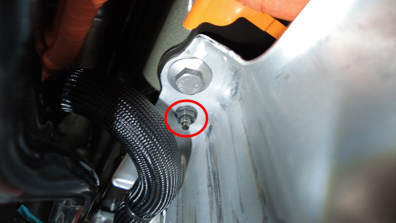
Remove upper nut securing HV battery
rear skid plate enclosure
注1x nut, 10mm, 13 Nm, Fastener count may vary on older built vehicles
-
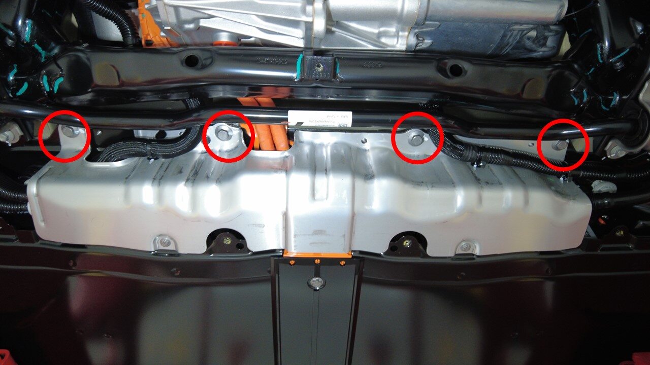
Remove upper bolts securing HV battery
rear skid plate enclosure
注4x bolts, 13mm, 35 Nm
-
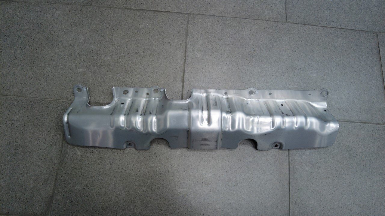
Remove HV battery rear skid plate
enclosure
-
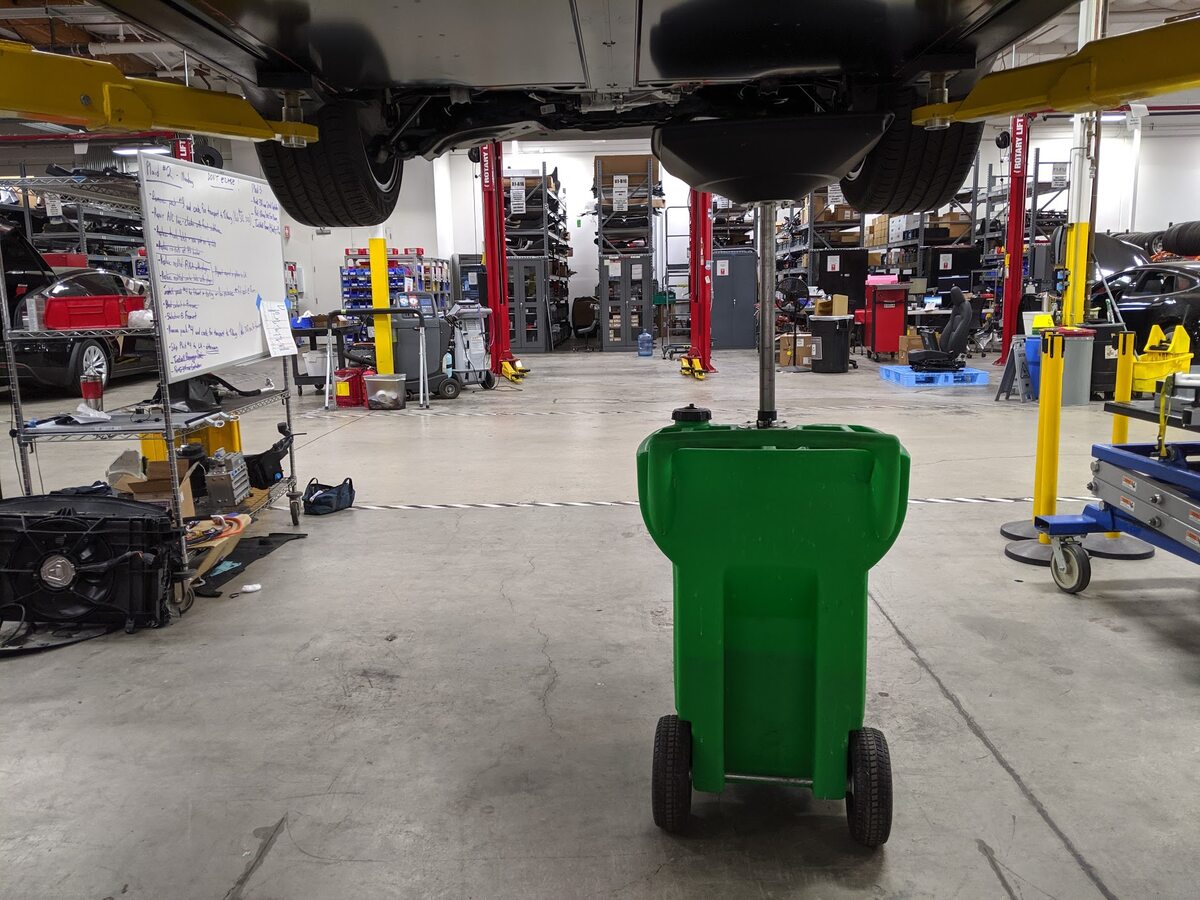
Position coolant drain container
underneath LH rear of HV battery
-
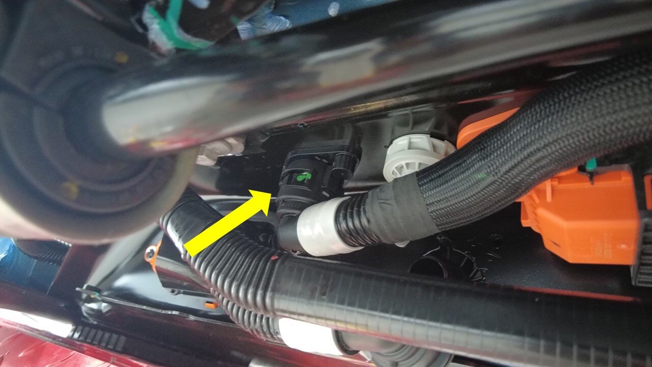
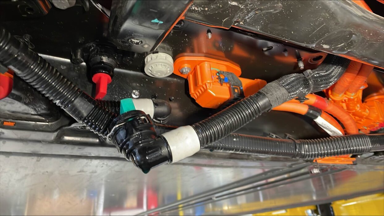
Disconnect RDU inverter inlet tube
from LH rear of HV battery
注1x spring clip, Plug hose connections as needed, Coolant loss greater than 1 L will require vacuum fill
-
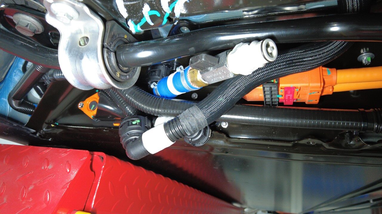
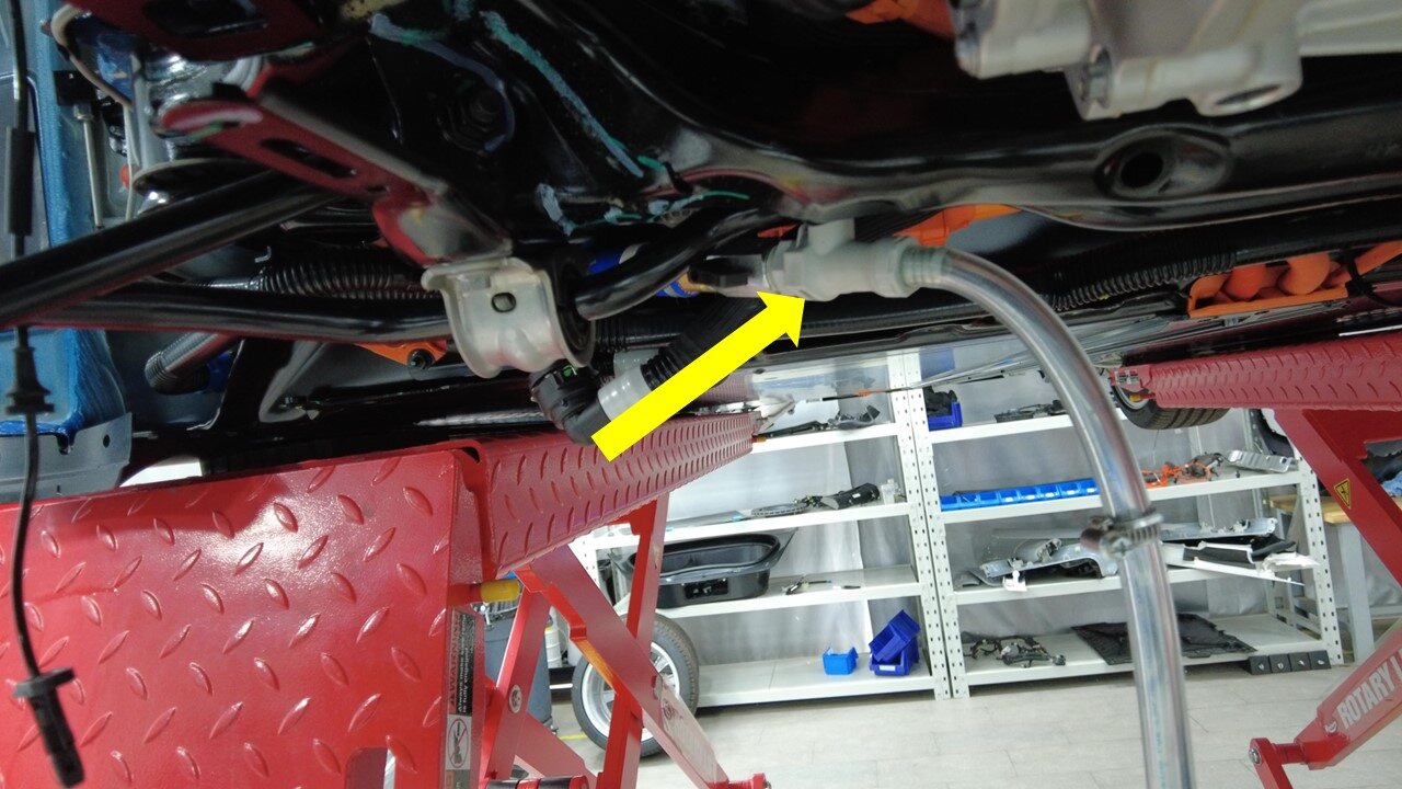
Attach coolant drain hose adapter to
PCS outlet hose coupling
注Use adapter with 90 degree angle, Make sure locking tab is fully seated
-
Attach coolant drain hose adapter to
coolant hose extension
-
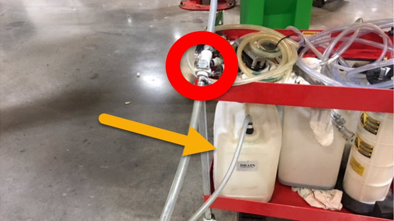
Attach coolant hose extension to
coolant drain hose
注Use caution as coolant may spill, Make sure to wear safety glasses
-
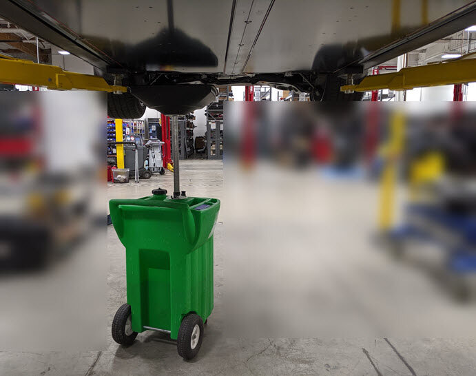
Position coolant drain container
underneath RH rear of vehicle
-
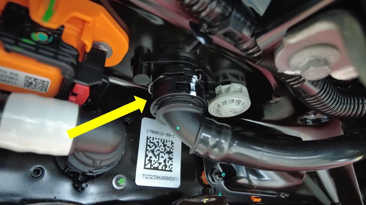
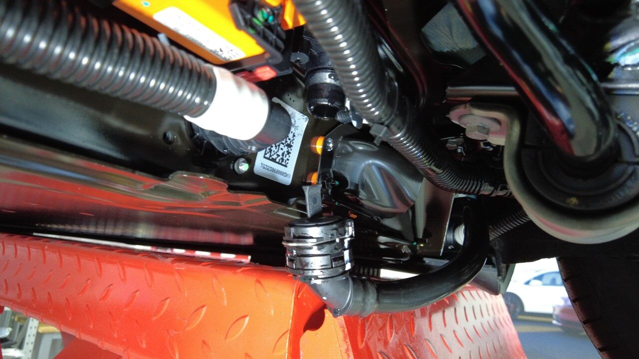
Disconnect rear PT supply hose from
rear of HV battery
注1x spring clip, Plug hose connections as needed, Coolant loss greater than 1 L will require vacuum fill
-
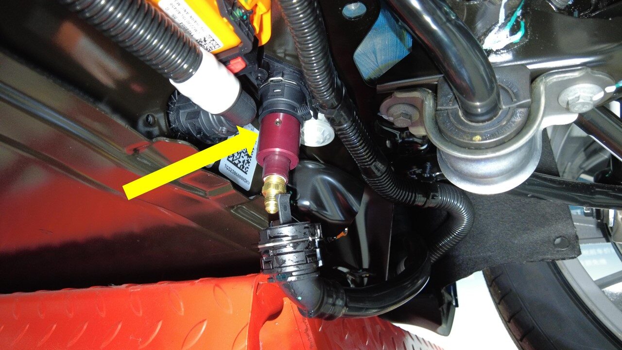
Attach coolant pressure tester to PCS
inlet hose coupling
注This adapter connected to regulated air line adapter, Make sure the locking tab is fully seated
-
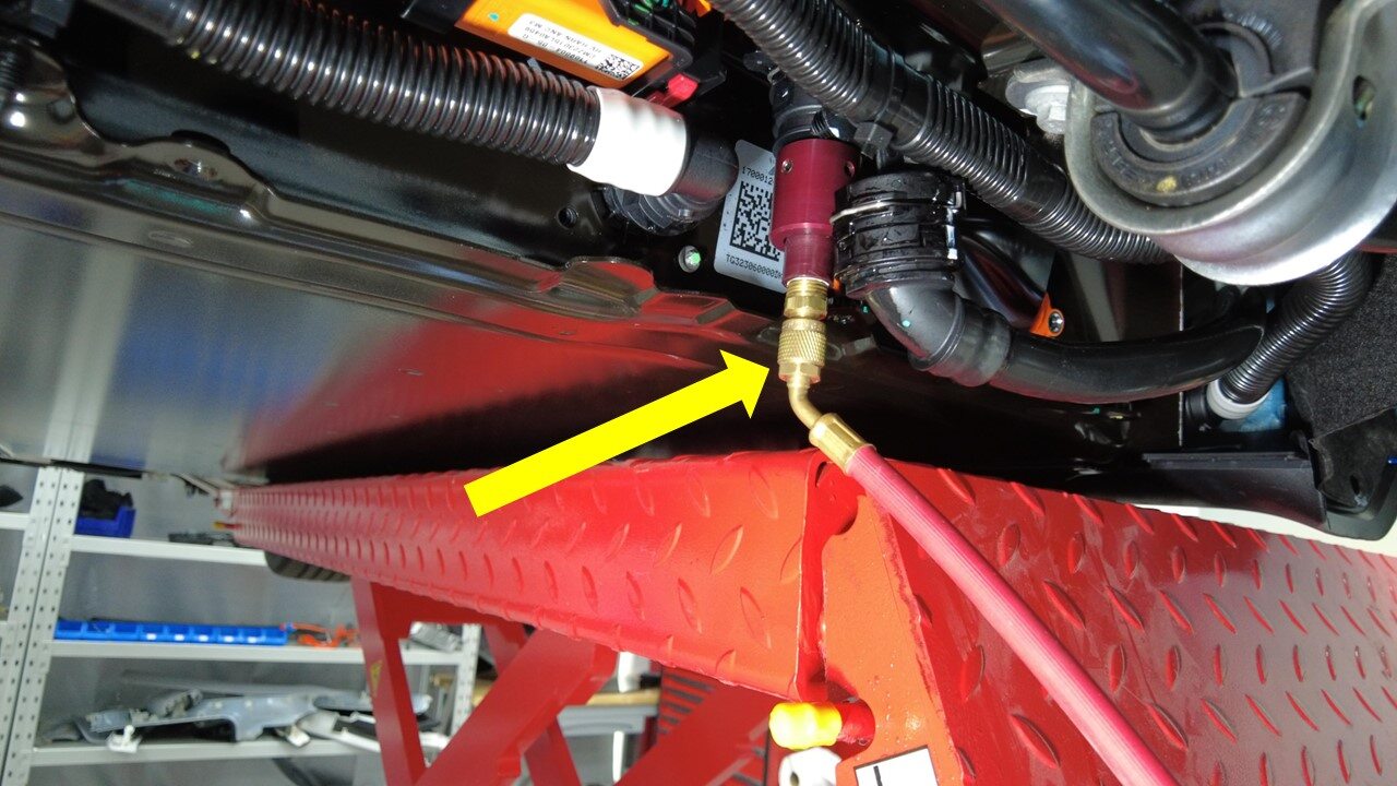
Attach coolant pressure tester to
pressure fitting adapter
-
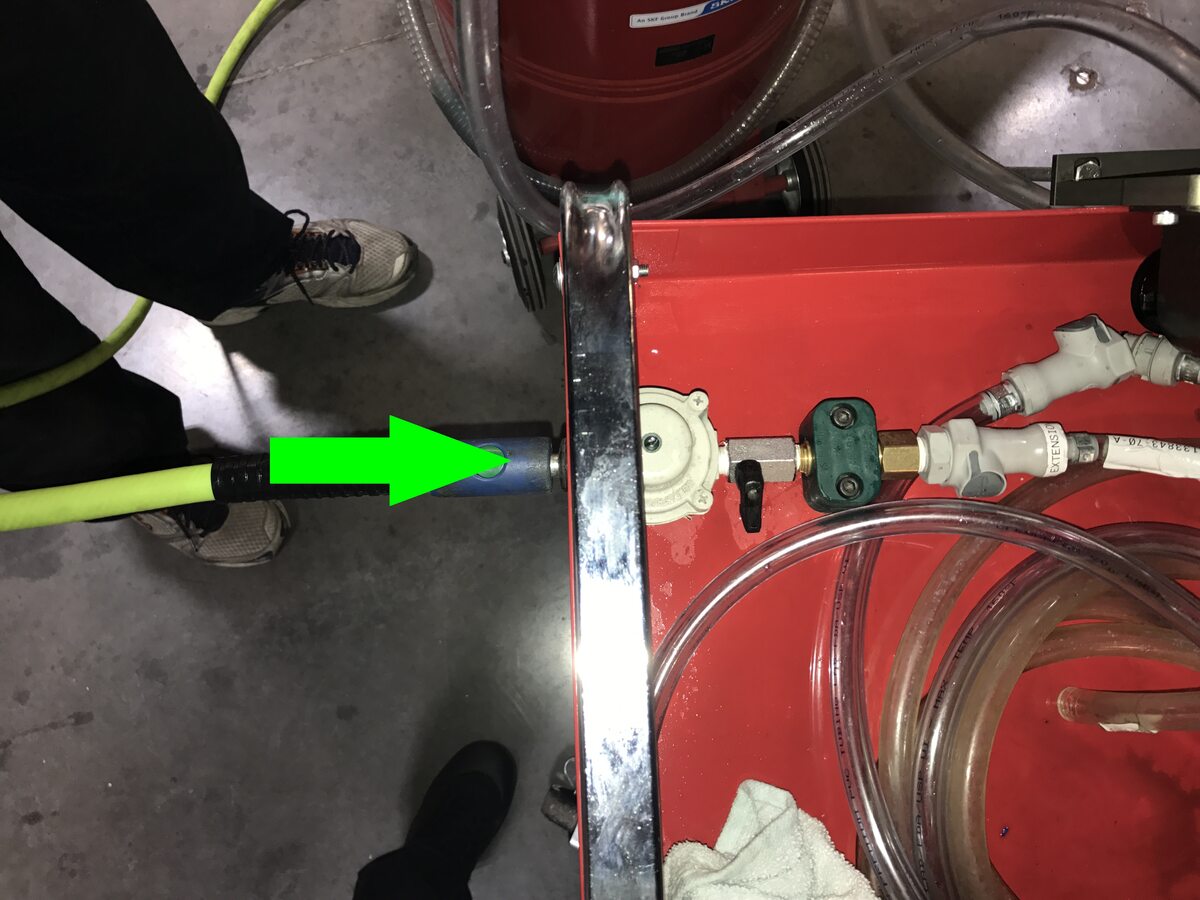
Attach compressed air line to coolant
pressure tester
注Verify valve is in closed position
-
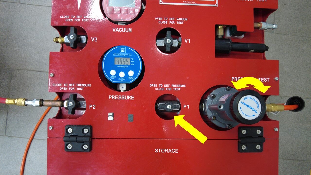
Open regulator valve then slowly
adjust regulator to 50 psi
注Use caution as coolant may spill, Make sure to wear safety glasses
-
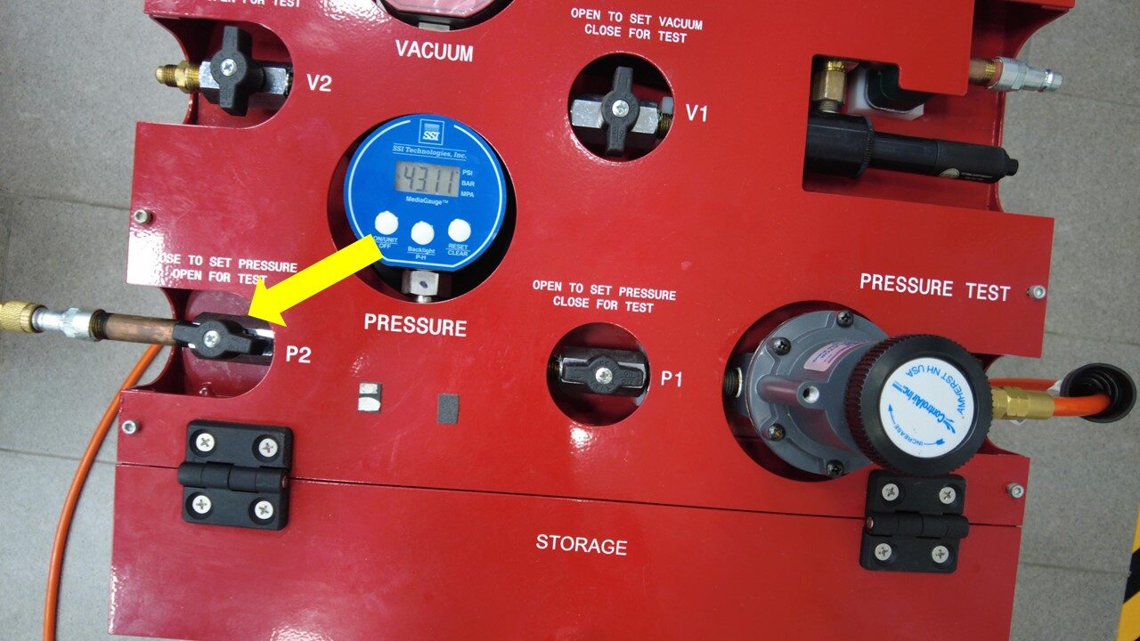
Open 2nd valve slowly
注Use caution as coolant may spill, Make sure to wear safety glasses
-
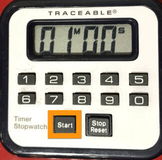
Set timer for 2 minutes and select
start
注Once timer is complete, select Stop Reset
-
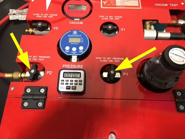
Close both valves
-
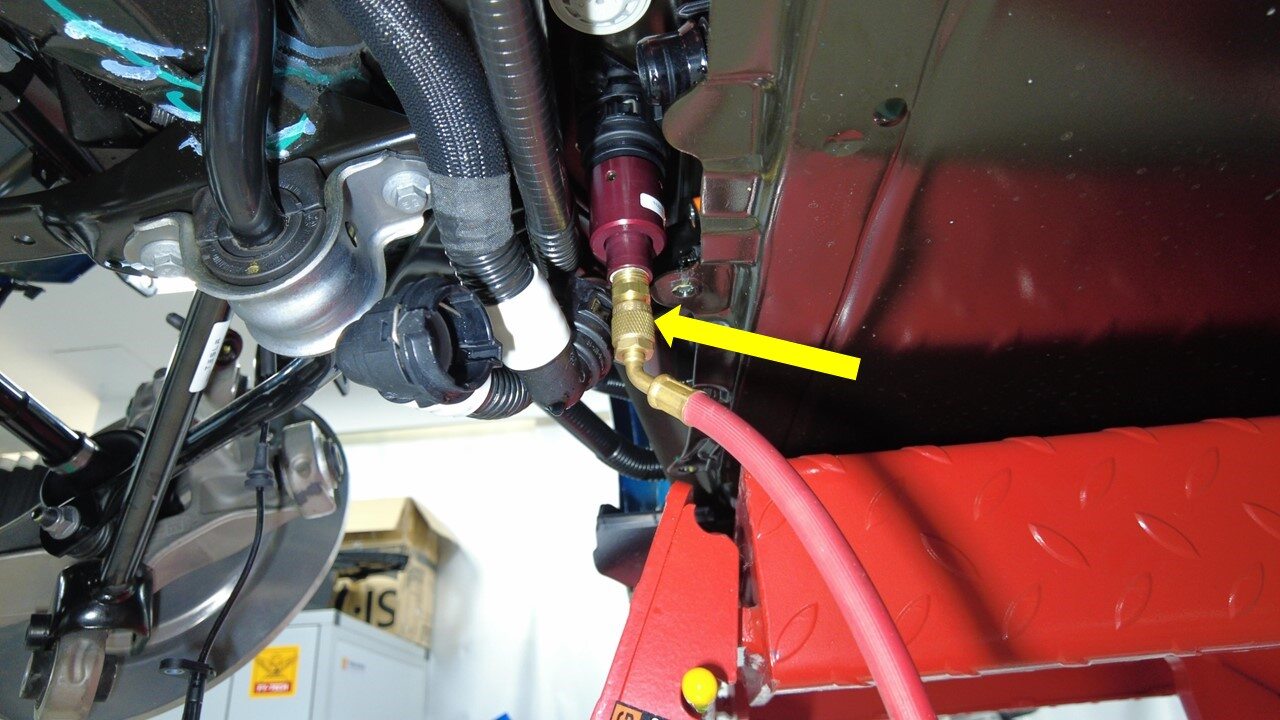
Remove pressure fitting adapter from
coolant pressure tester
-
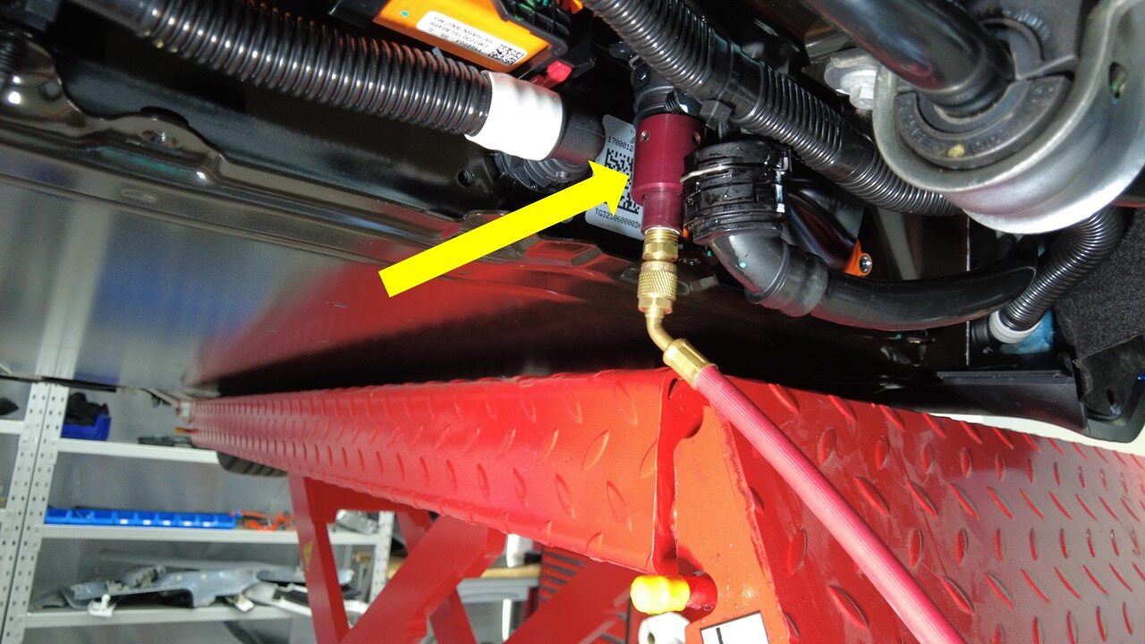
Remove coolant pressure tester from
PCS inlet hose coupling
-
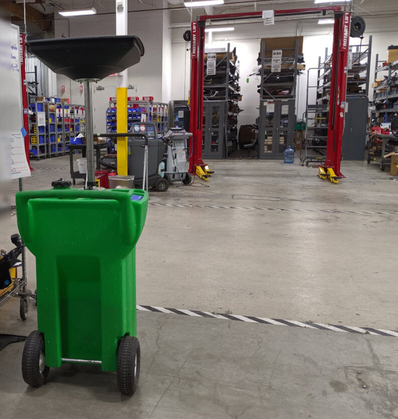
Remove coolant drain container from
underneath vehicle
-
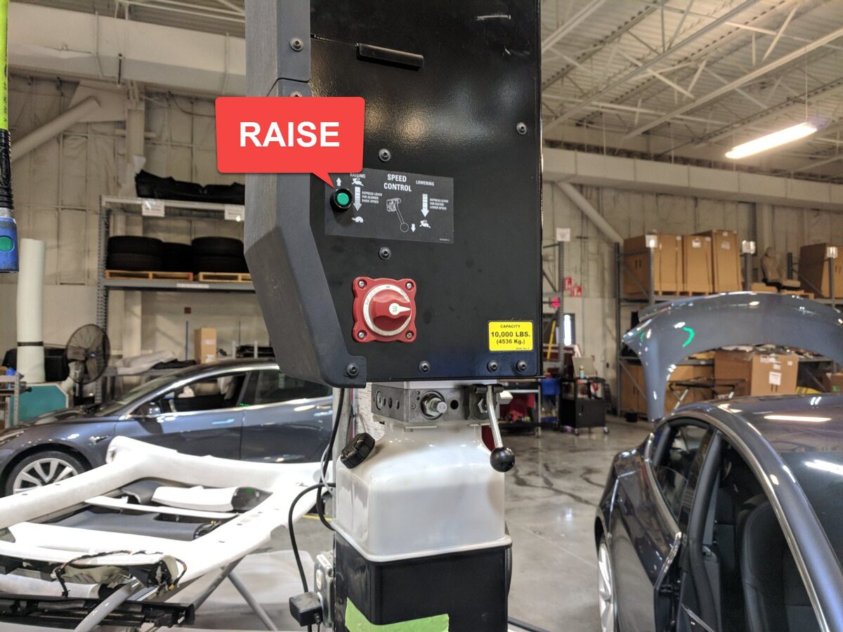
Lower vehicle until tires are touching
the ground
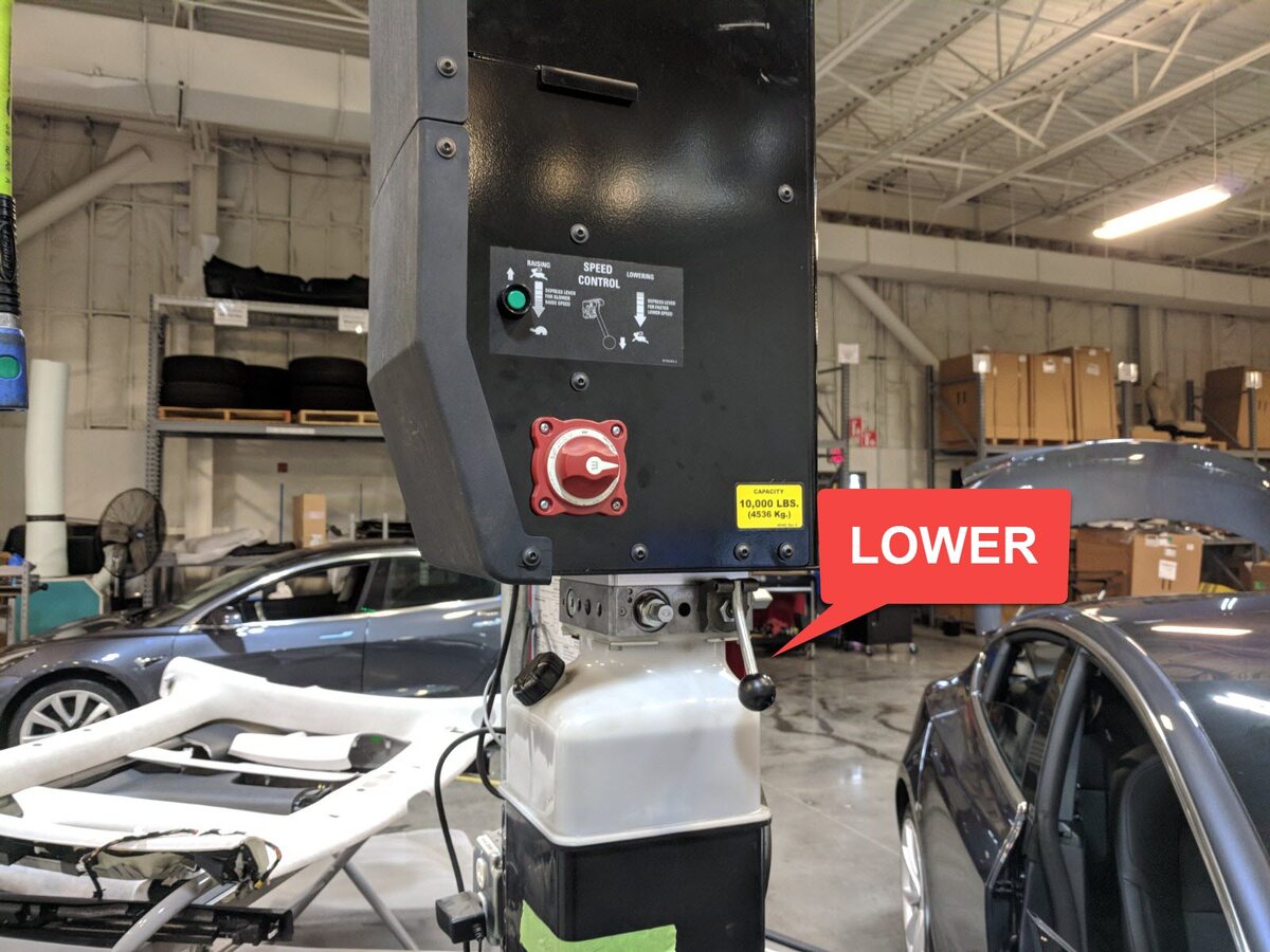
注Raise lift off locks, then hold lock release lever to keep locks free while vehicle is lowered

-
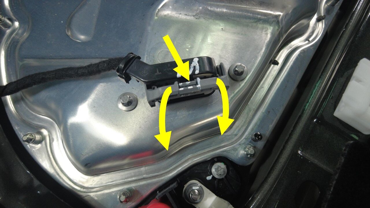
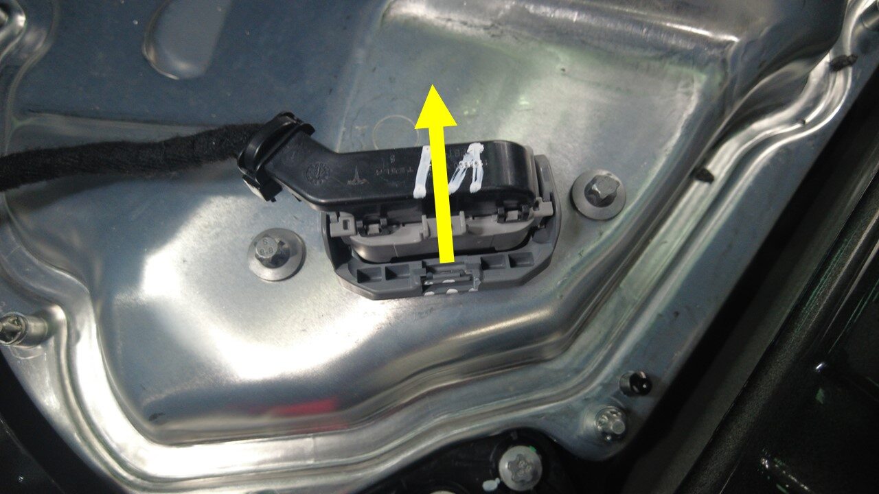
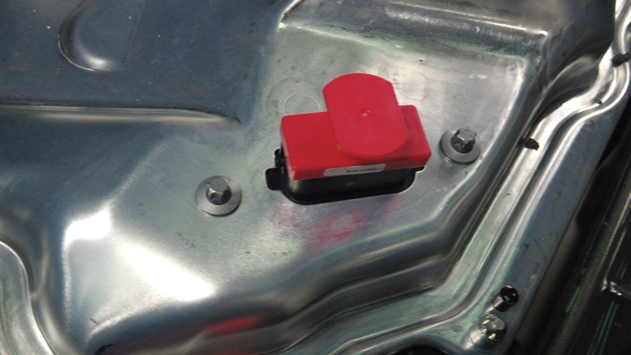
Disconnect HVC logic connector and
install logic cap
注1x connector, 1x cap, Release locking tab then push the handle downward to release connector
-
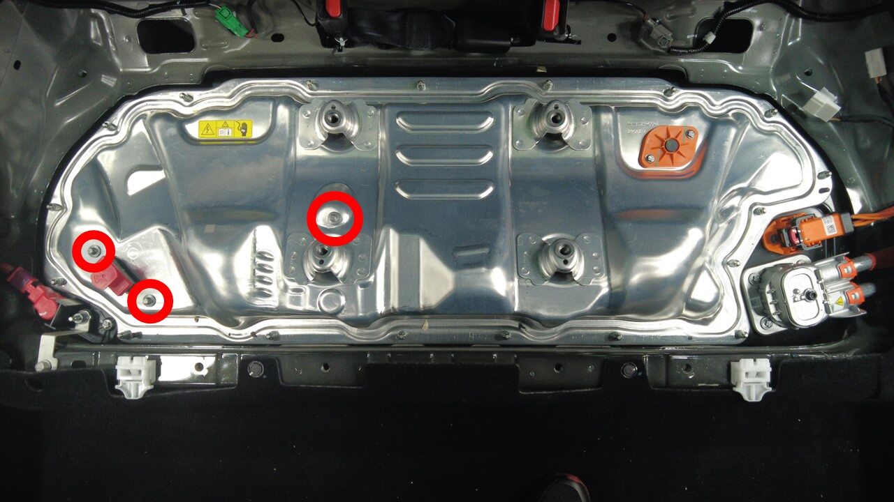
Remove bolts securing the ancillary
bay cover to HVC
注3x bolts, E10, 5 Nm + 30 degrees
-
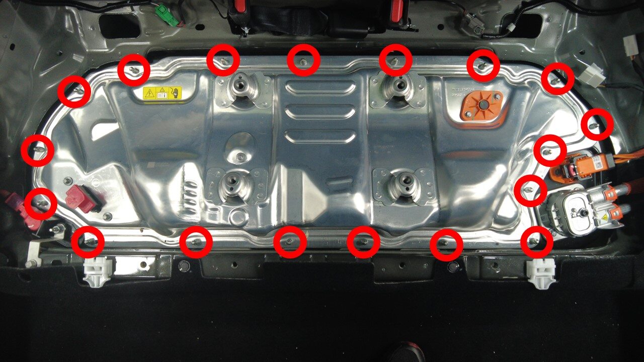
Remove bolts securing the ancillary
bay cover to HV battery
注18x bolts, E10 5-Lobe, 8 Nm, Use E10 5-Lobe socket without magnet, The fasteners are captive and will stay attached to the ancillary bay cover
-
Inspect HV insulating gloves
注Check gloves for damage prior to use, Refer to service document TN-15-92-003 R1, for information on inspecting HV gloves. https://service.teslamotors.com/protected-doc/ServiceBulletins/External/TN/TN-15-92-003_High_Voltage_Awareness_Care_Points_R4.pdf
-
Put on HV insulating gloves and
leather over gloves
注Make sure to wear Electrical Protective Gloves any time Hioki tester is used
-
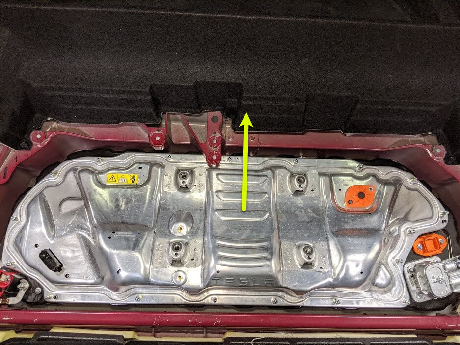
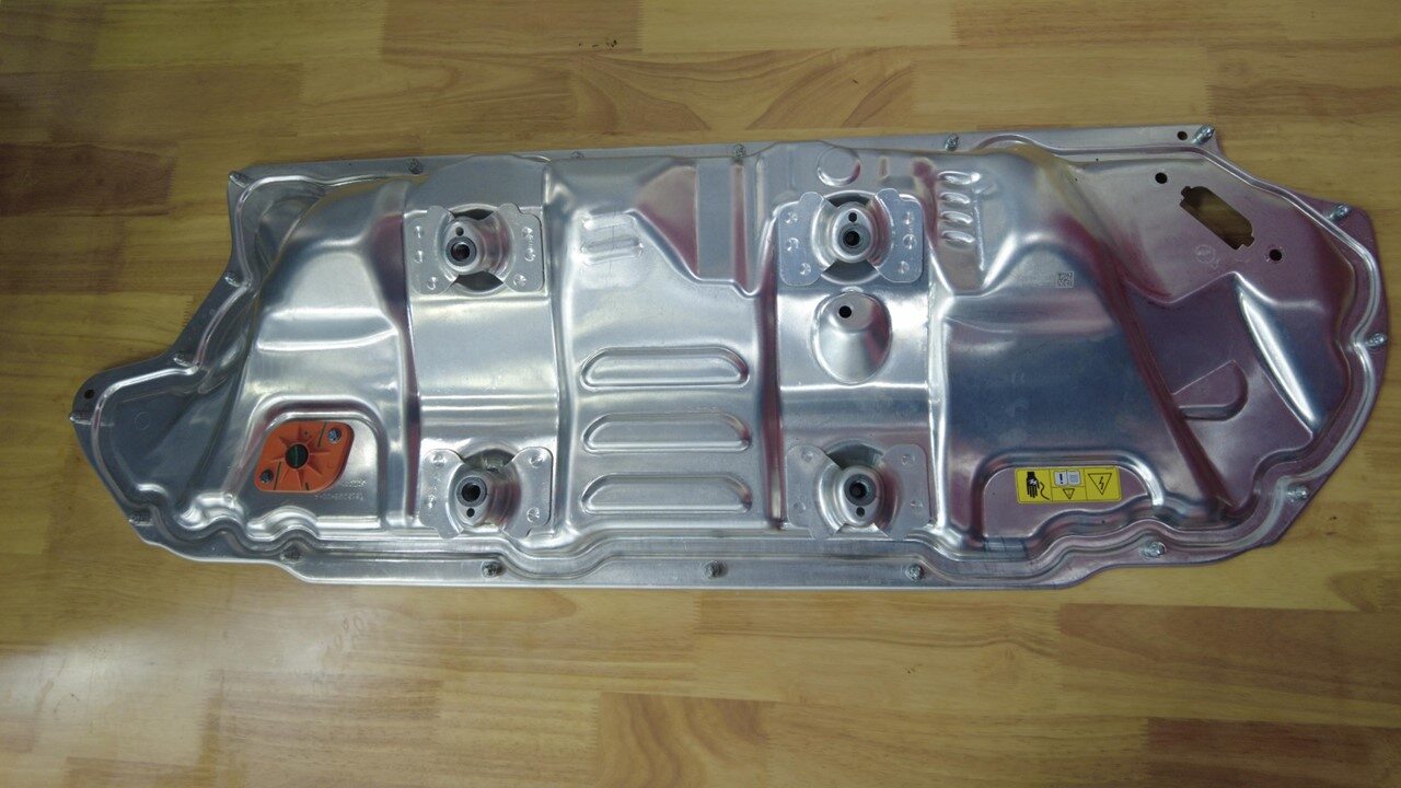
Remove the ancillary bay cover from HV
battery
-
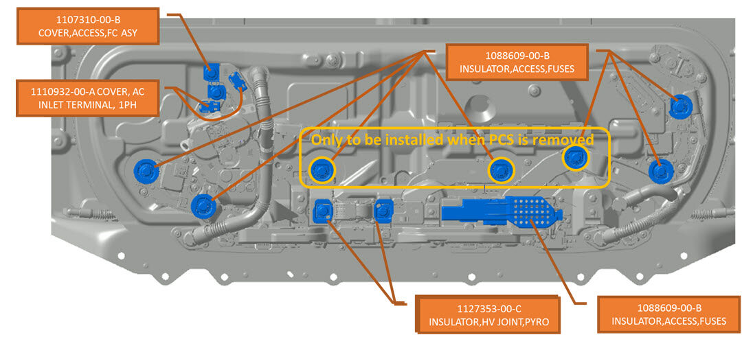
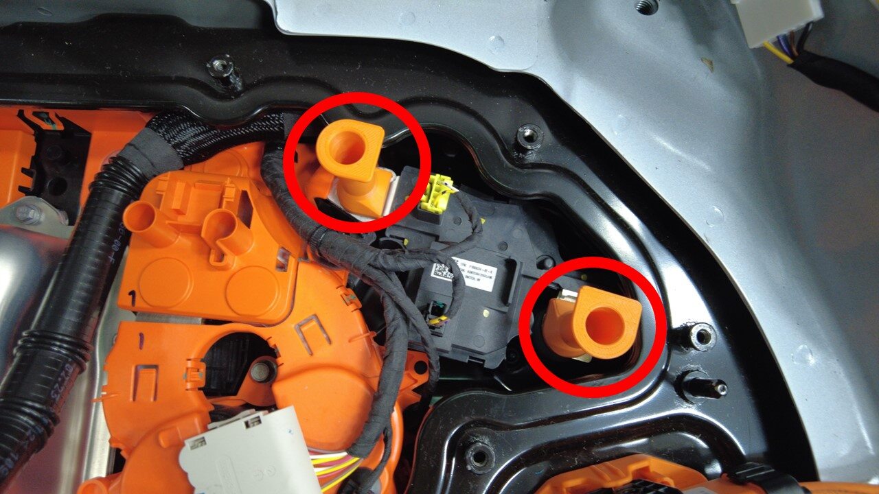
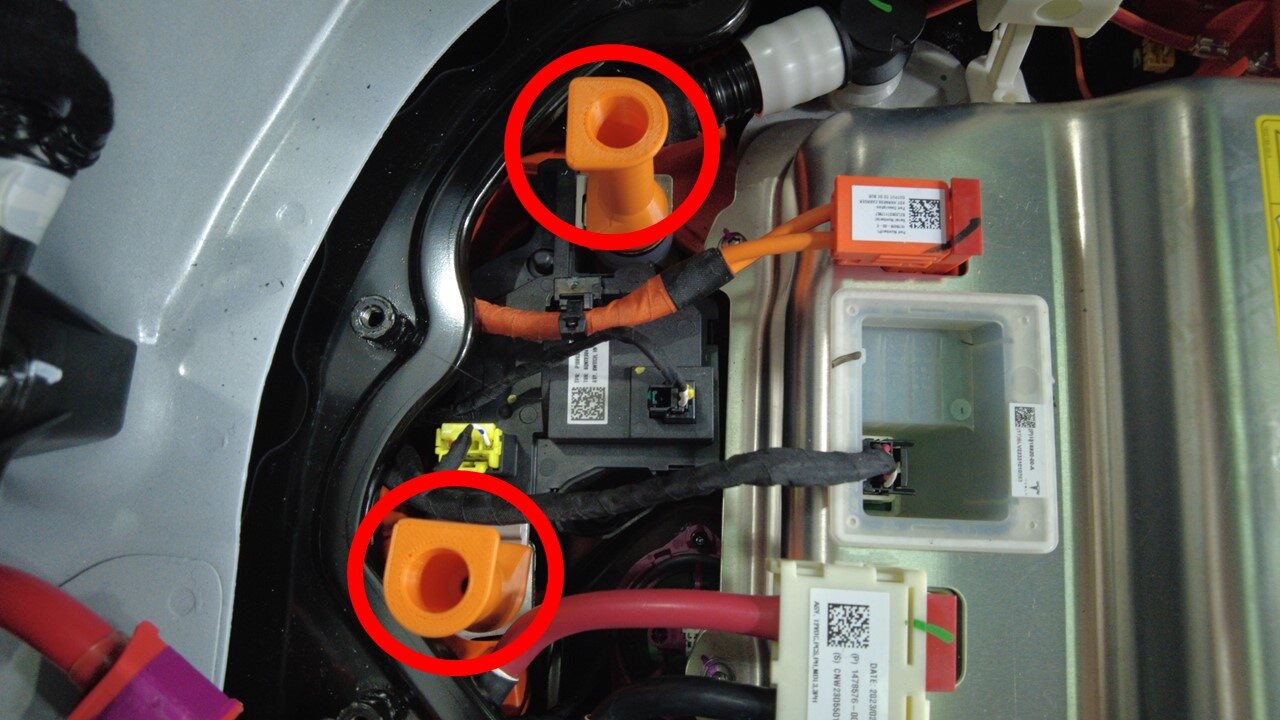
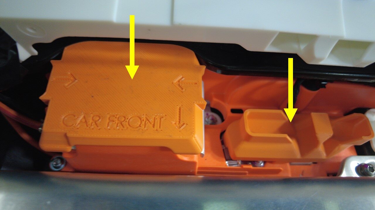
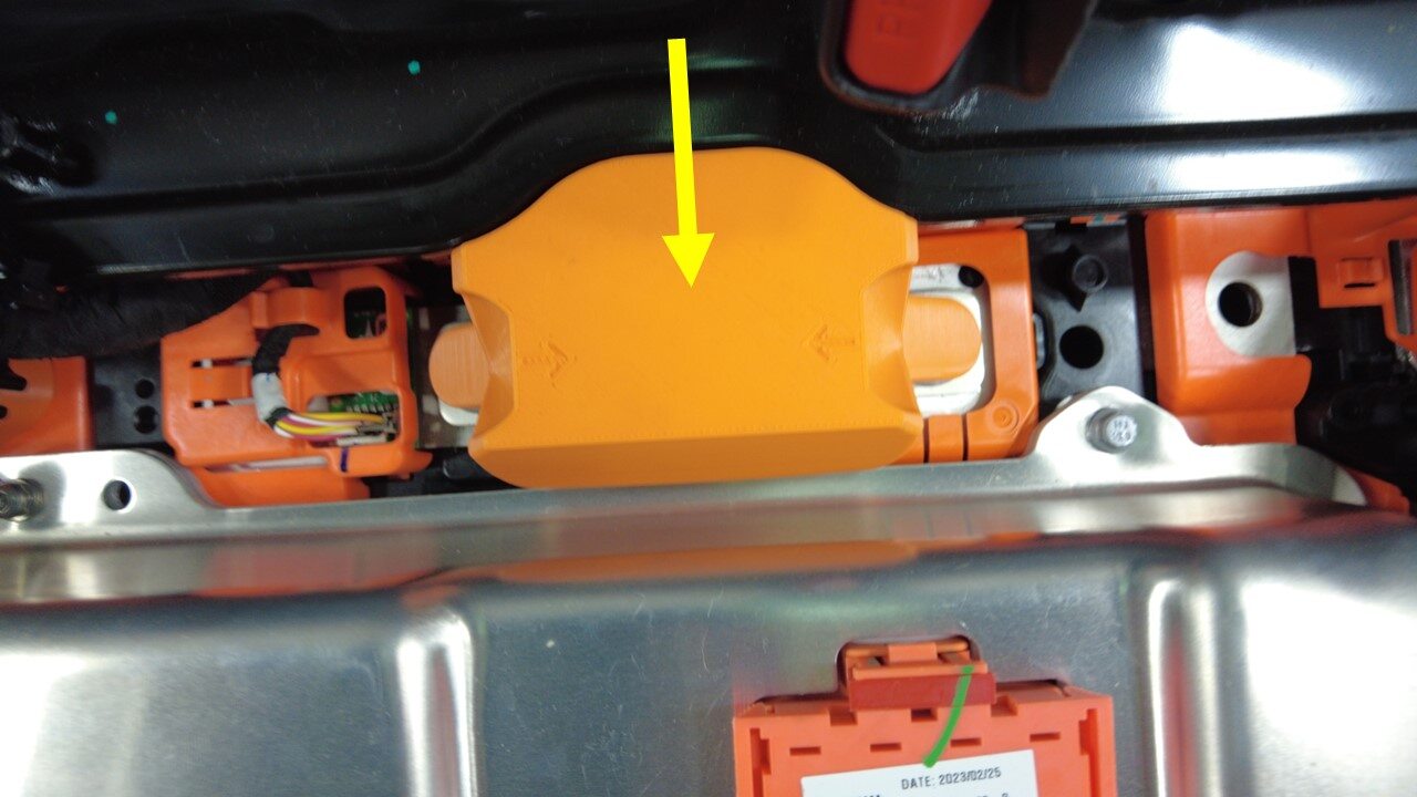
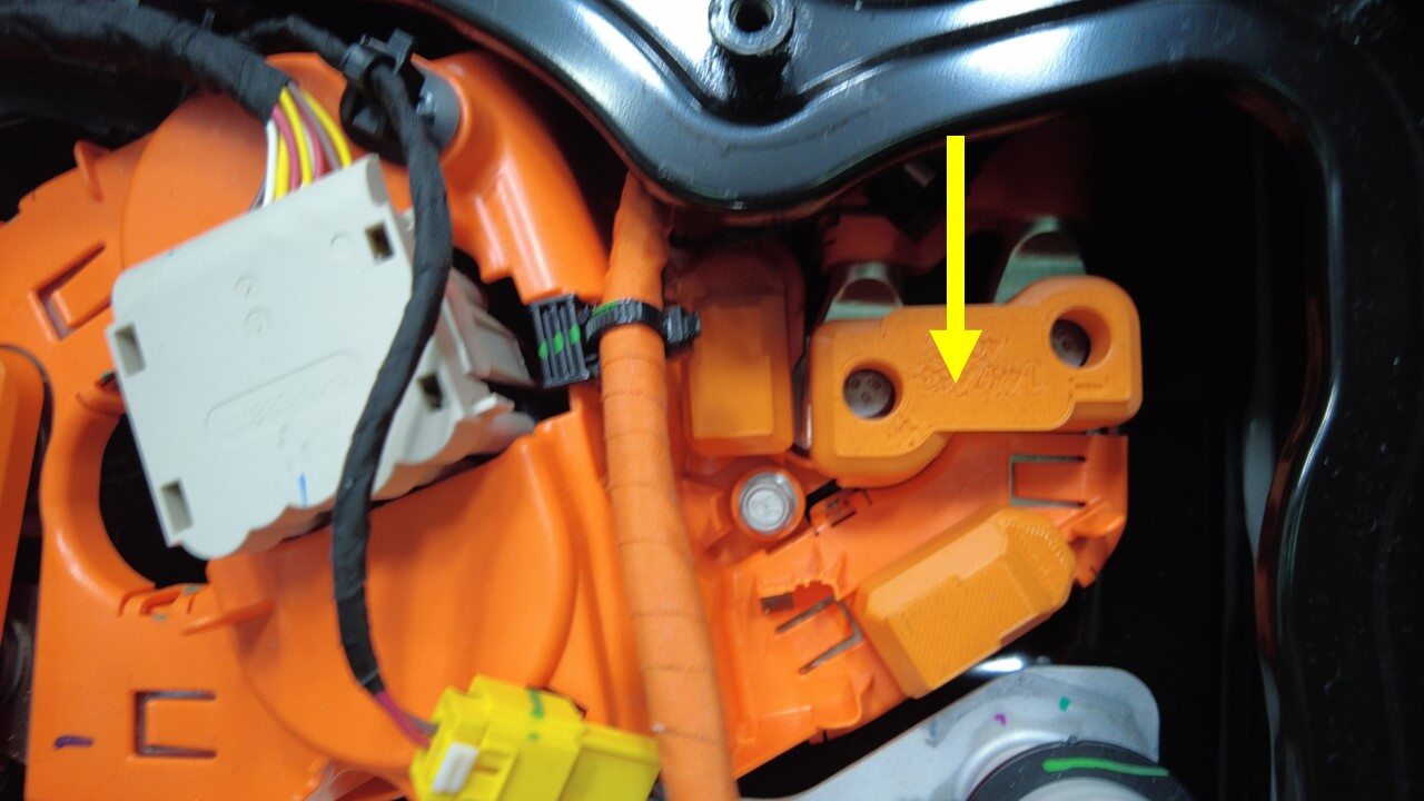
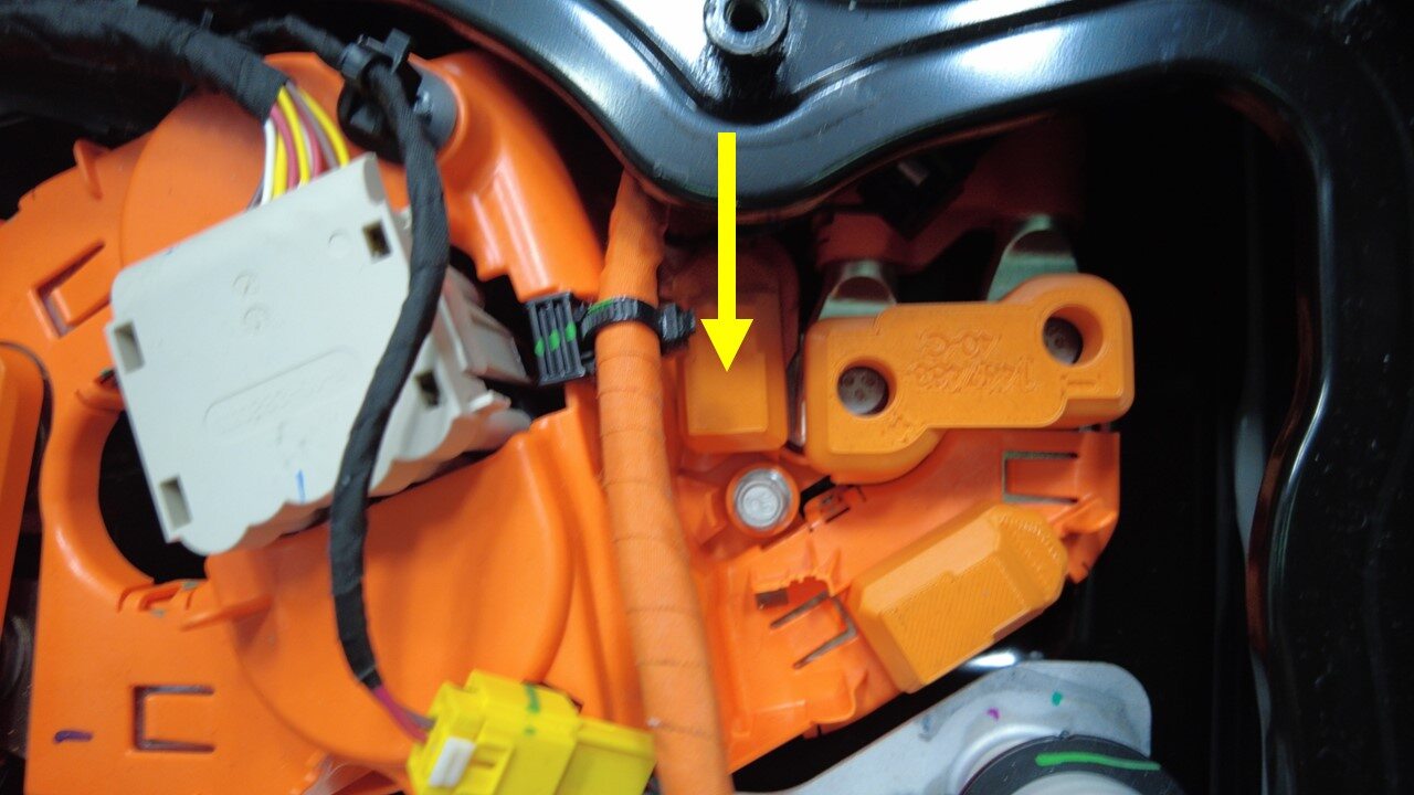
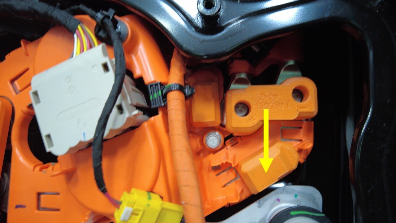
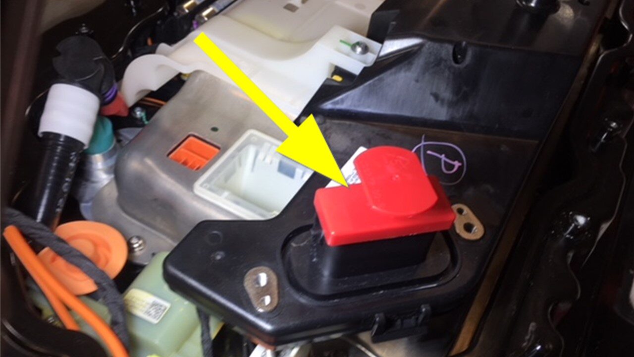
Inspect the ancillary bay for any
missing insulators
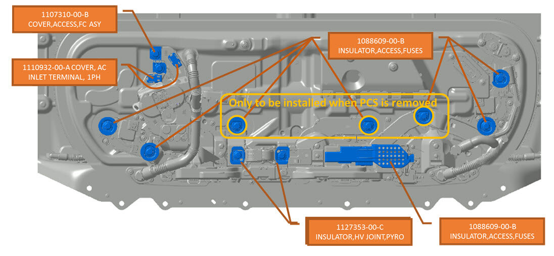
注Install service insulator kit before continuing to next step, The number of bolts on newer vehicles may vary
-
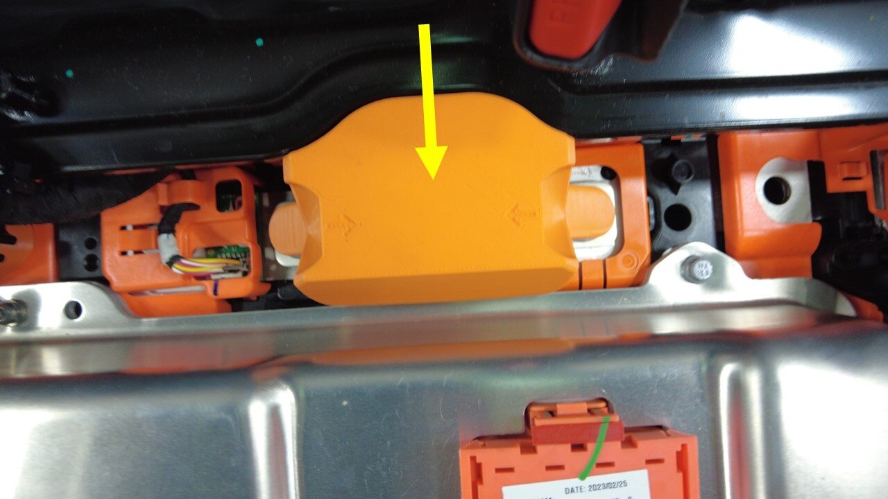
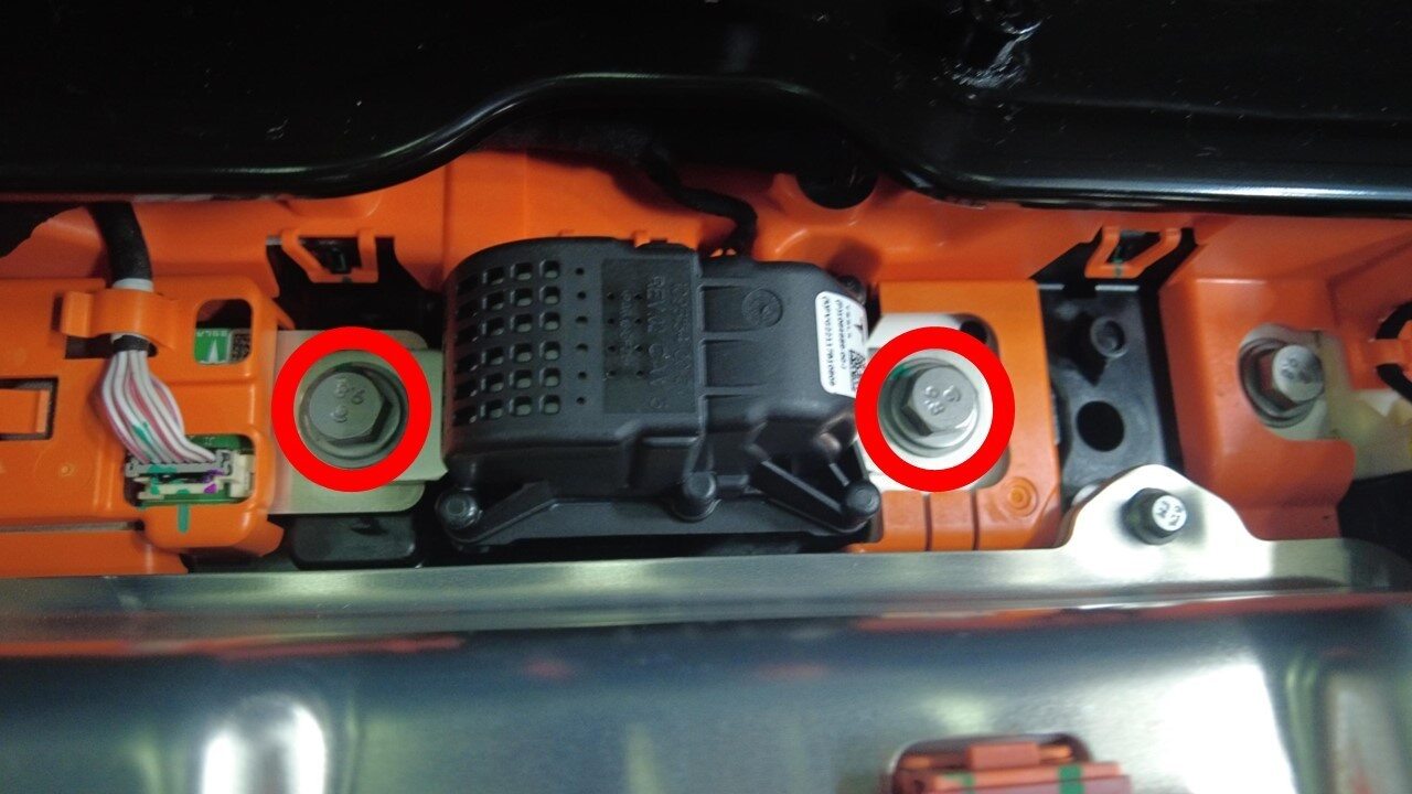
Remove bolts securing pyro disconnect
to the ancillary bay
注1x insulator, patch bolts, 13mm, 9 Nm, Discard after removal
-
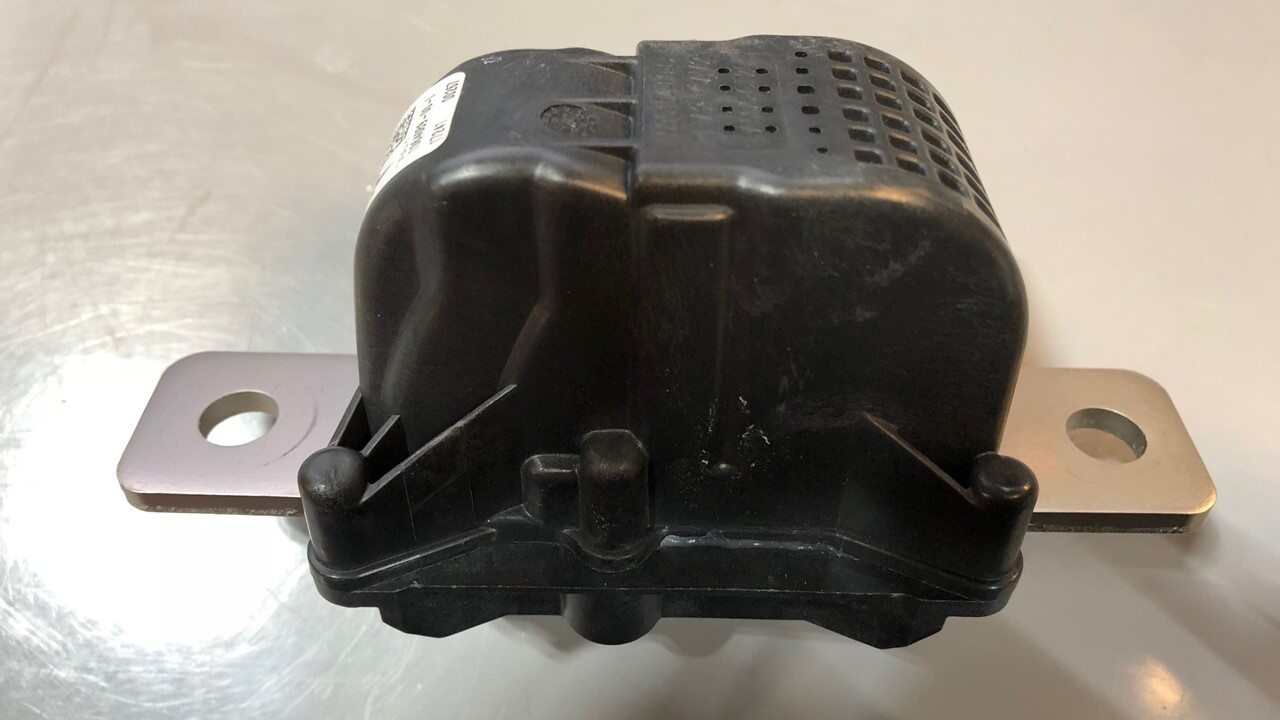
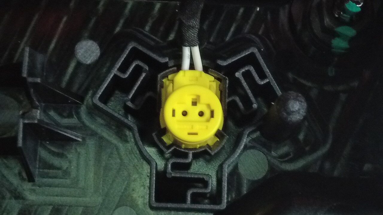
Remove pyro disconnect from the
ancillary bay
注1x connector from the bottom, Lift pyro disconnect straight up and out of the ancillary bay
-
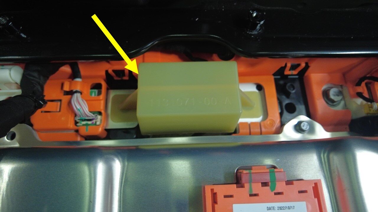
Install pyro disconnect dummy
-
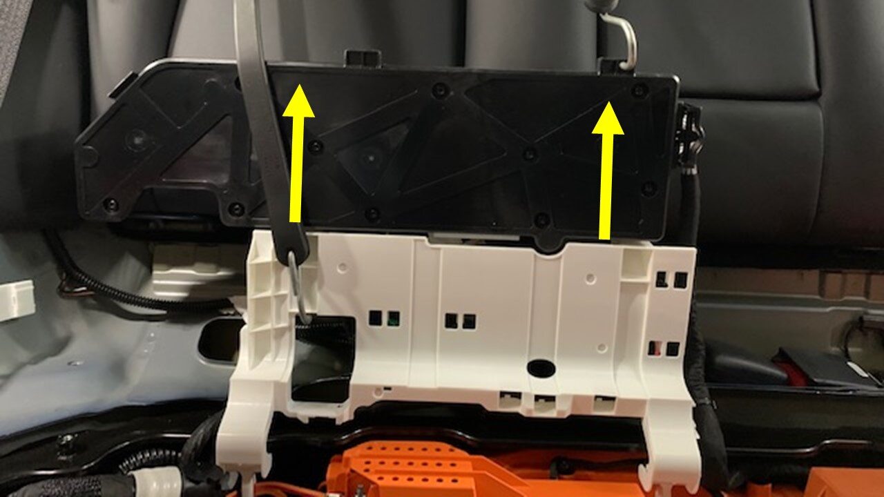
Use bungee to secure HVC in an upwards
position
注Wrap bungee around RH headrest
-
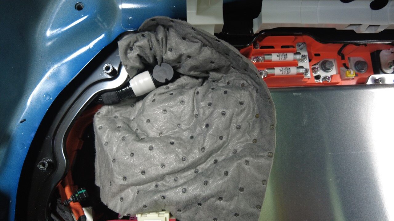
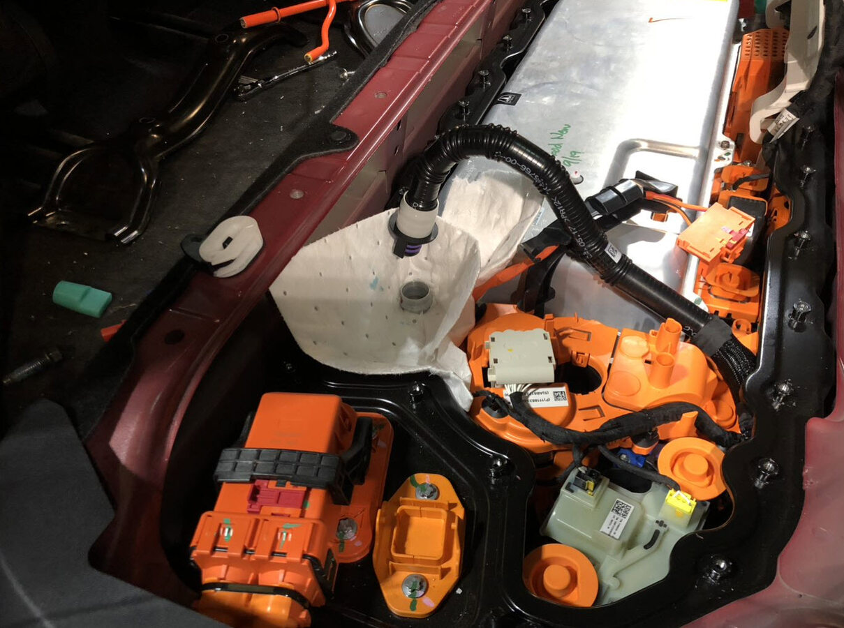
Position absorbent sheets below and
around PCS coolant inlet hose to avoid excess coolant dripping
-
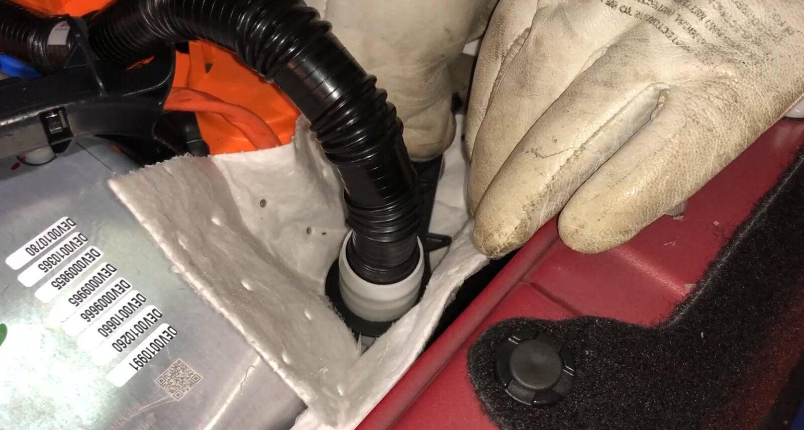
Disconnect PCS coolant inlet hose from
PCS
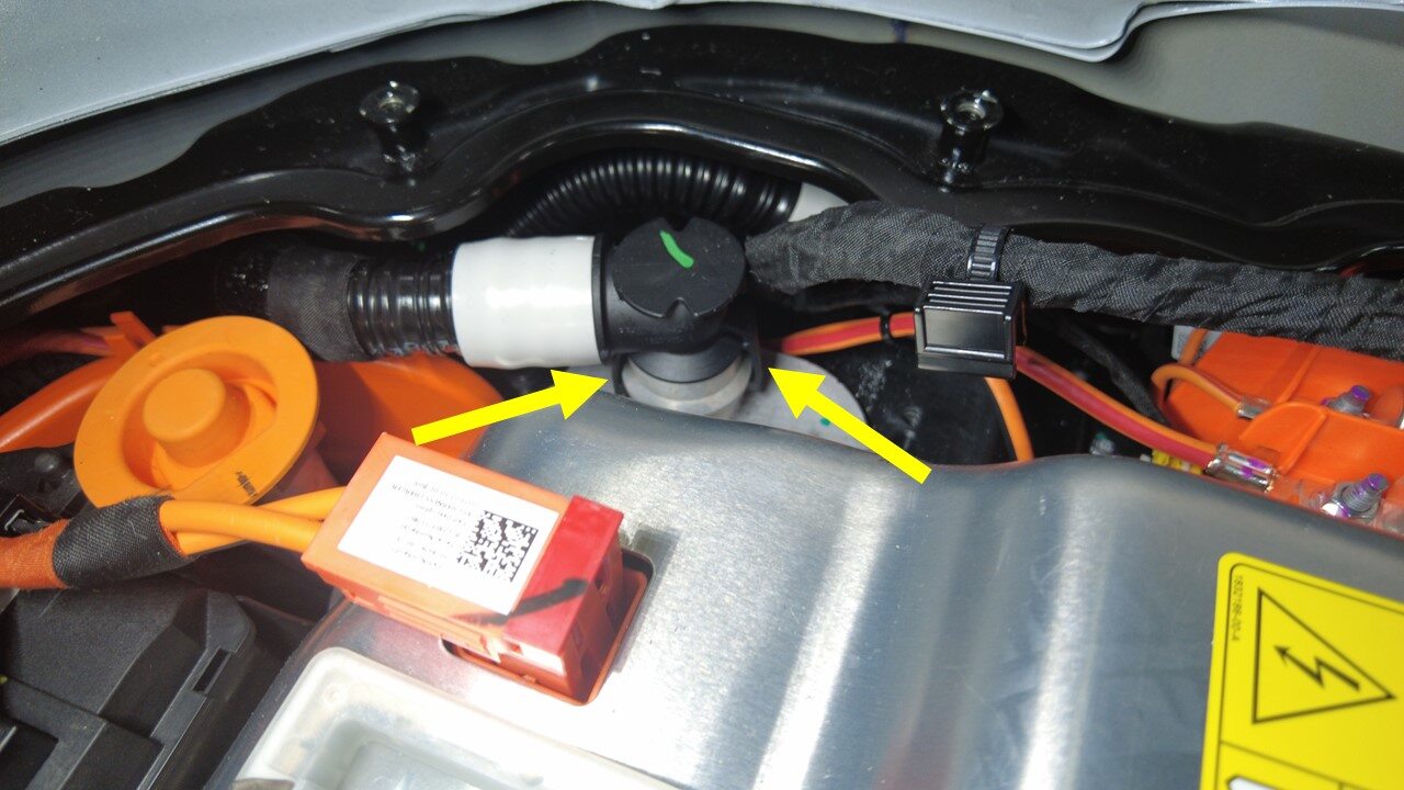
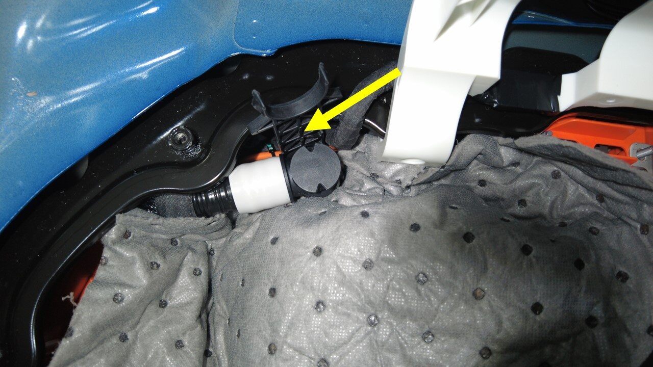
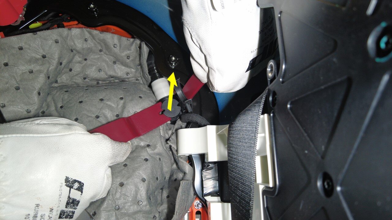
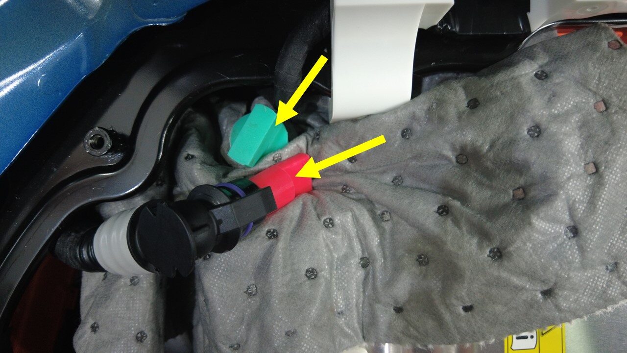
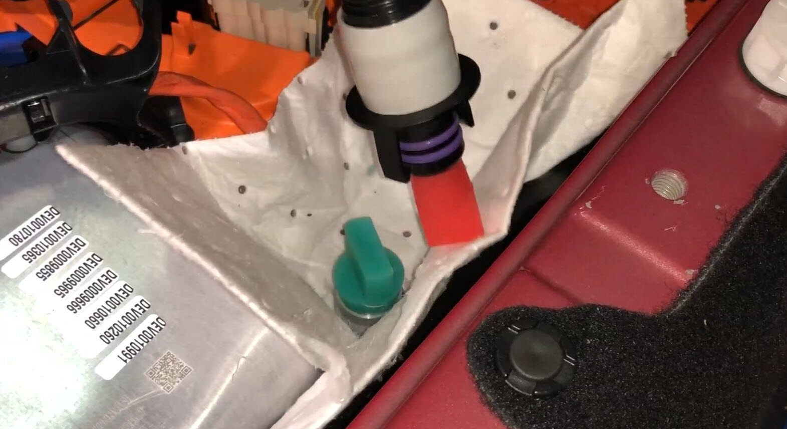
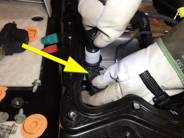
注2x clips, 2x plugs, Insert the special tool away from the PCS, between the ancillary bay housing and the hose, There is not sufficient room to install the special tool on the PCS side, May cause damage to the tool or the hose retainers, Install plugs to PCS and hose
-
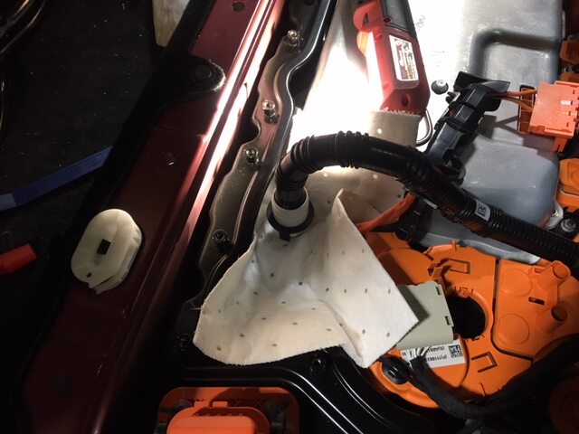
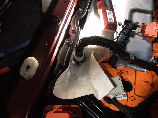
Position absorbent sheets below and
around the PCS coolant outlet hose to avoid excess coolant dripping
-
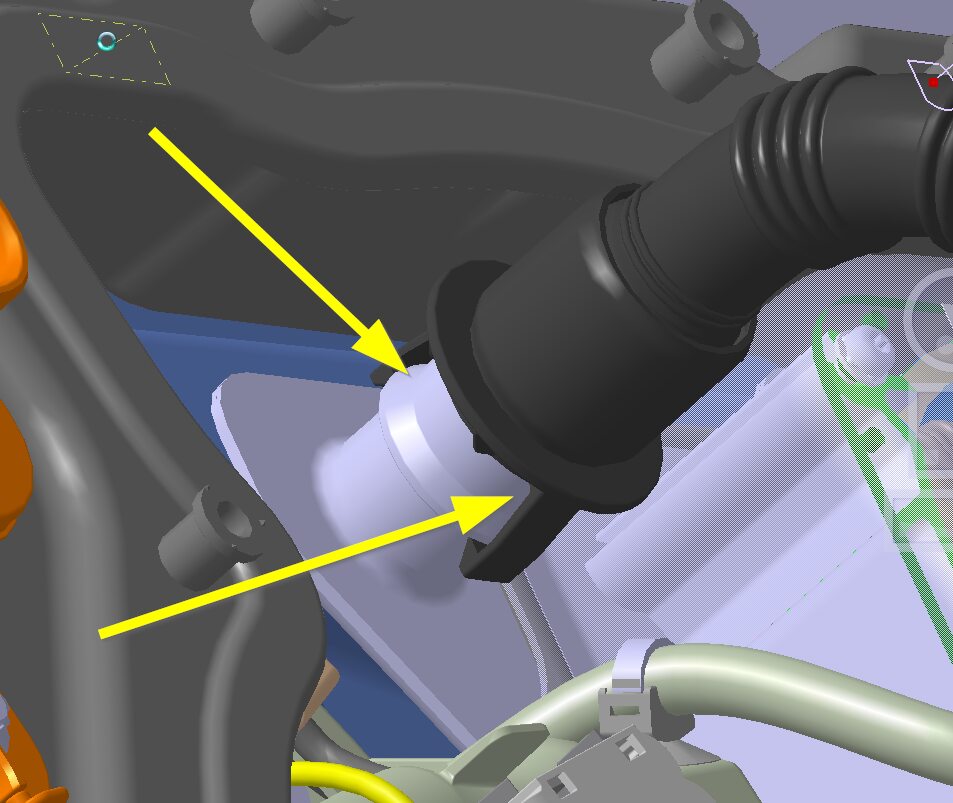
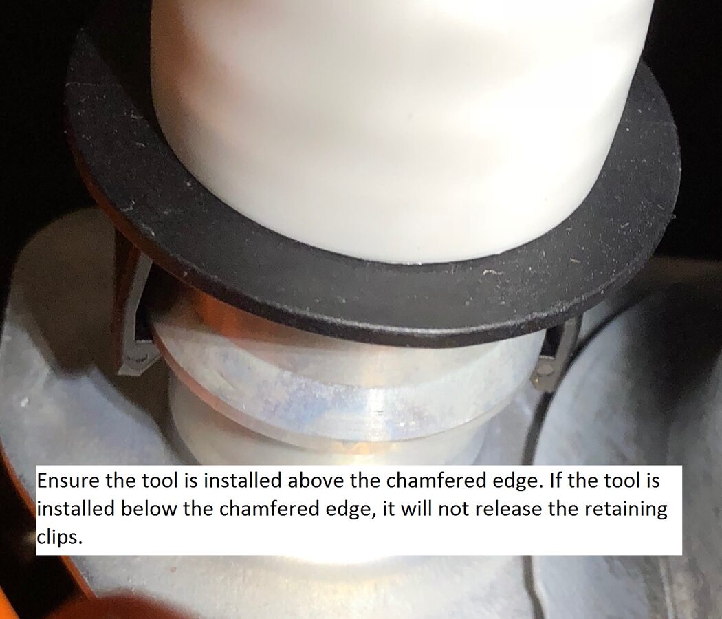
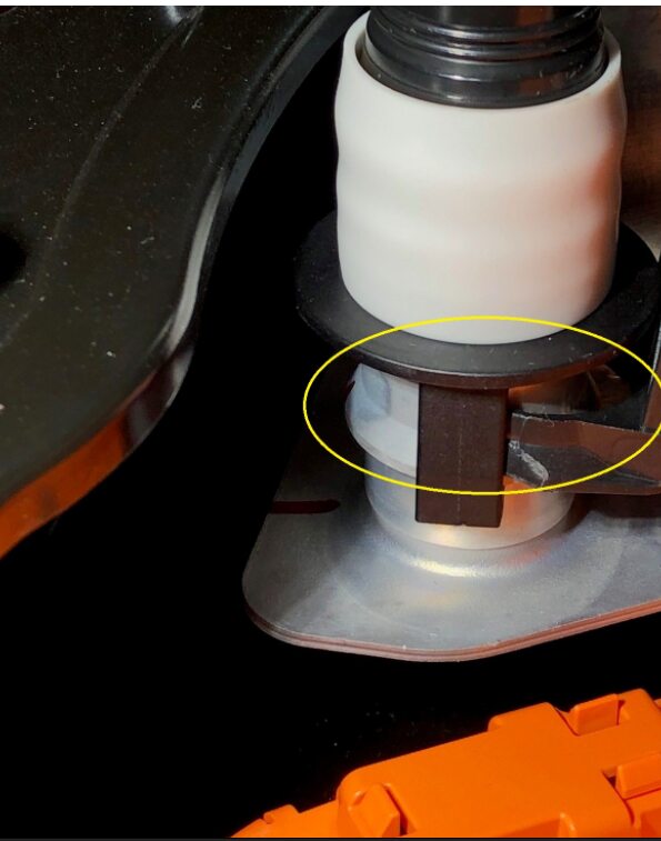
Disconnect PCS coolant outlet hose
from PCS and install plugs
注1x hose, Use the special tool to release the 2x clips
-
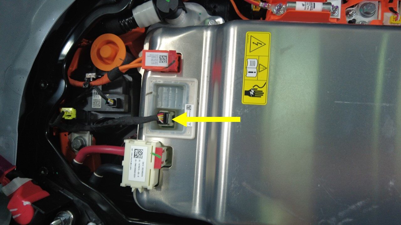
Disconnect PCS logic connector from
PCS
注1x connector
-
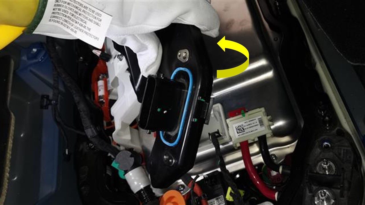
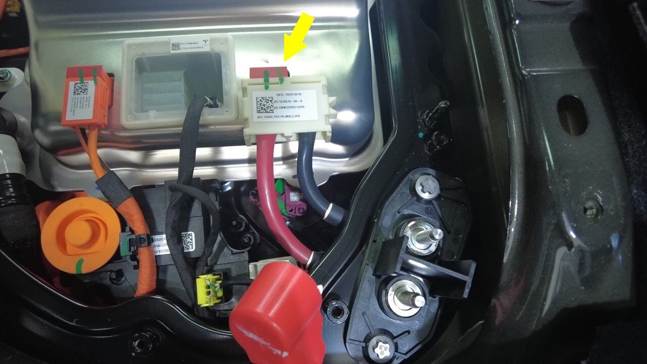
Disconnect PCS LV connector from
PCS
注1x connector, Release the locking tab by pulling upward, May need plastic trim tool to help lift the connector upwardLift the HVC up from the front
-
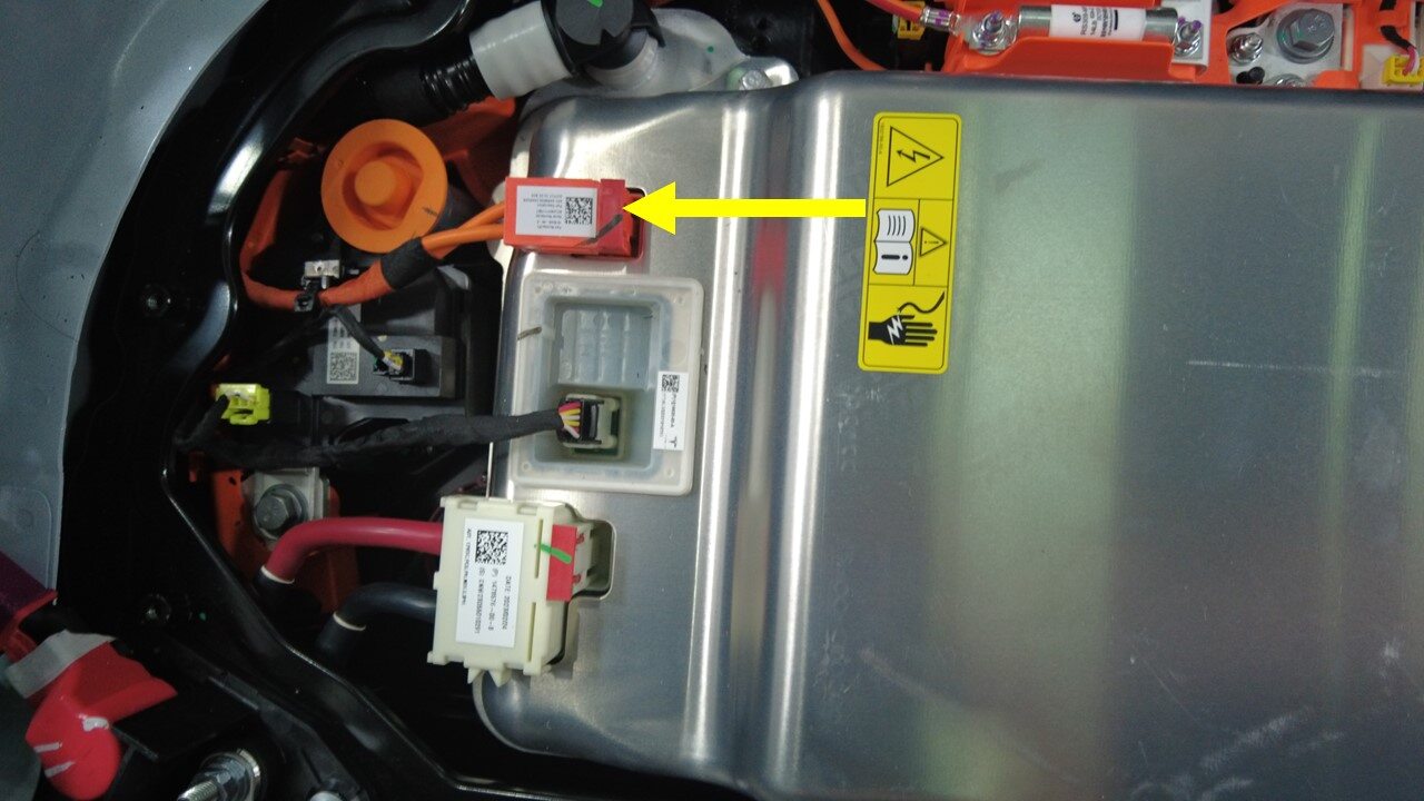
Disconnect PCS to DC bus HV
connector
注1x connector, Release the locking tab by pulling upward, May need plastic trim tool to help lift the connector upward
-
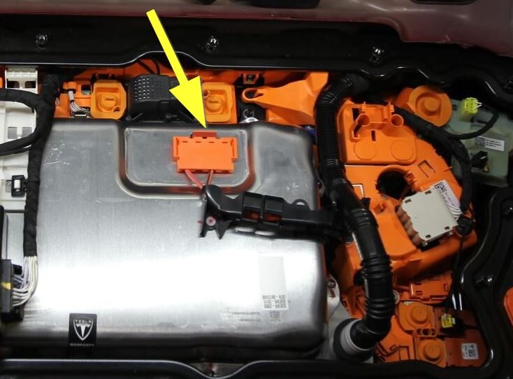
Disconnect PCS to fastcharge contactor
HV harness connector
注1x connector, Release the locking tab by pulling upward, May need plastic trim tool to help lift the connector upward
-
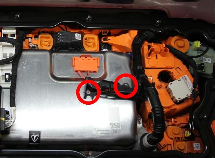
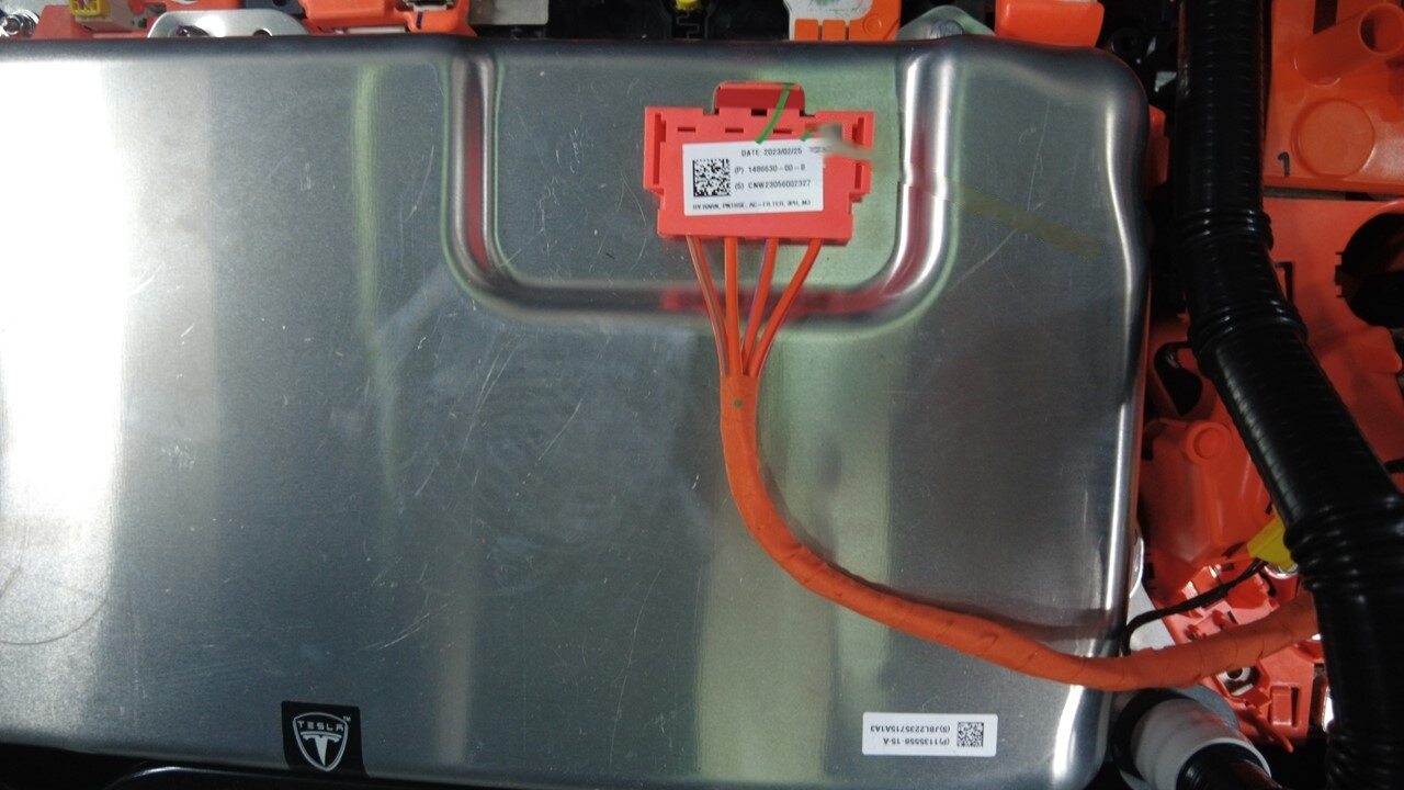
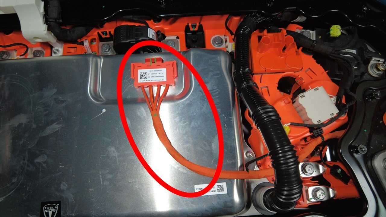
For vehicles that have a 1-Phase
charging system: release the clips (x2) that attach the PCS to fastcharge contactor HV
harness to the PCS and set the harness aside.
注There are differences in different regions, depending on having a 1-Phase or 3-Phase charging system: 1-Phase has a wiring harness fixing bracket, 3-Phase comes without this bracket.
-
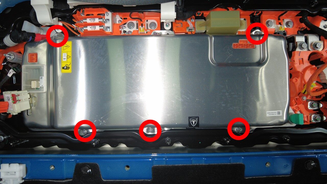
Remove bolts securing PCS to HV
battery
注5x bolts, 8mm, 18 Nm, Ensure onlythe 8mm fasteners are removed, Do not remove the T30 fasteners
-
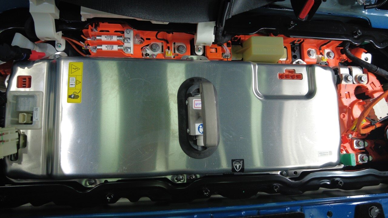
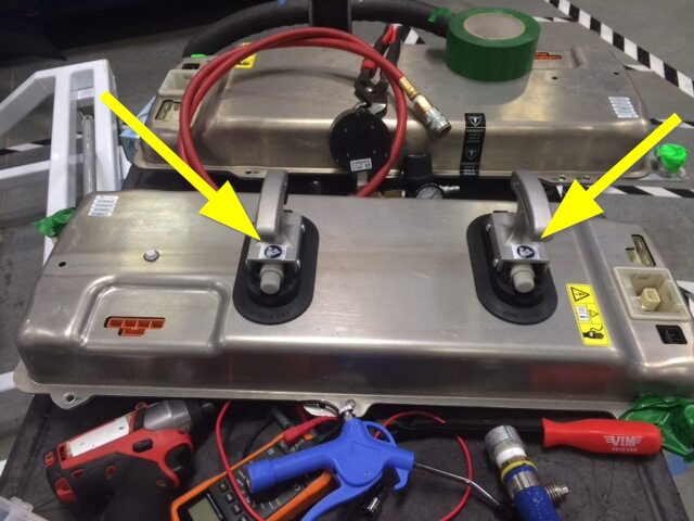
Secure suction cups to PCS
注Continue pressing plunger until red line is no longer visible
-
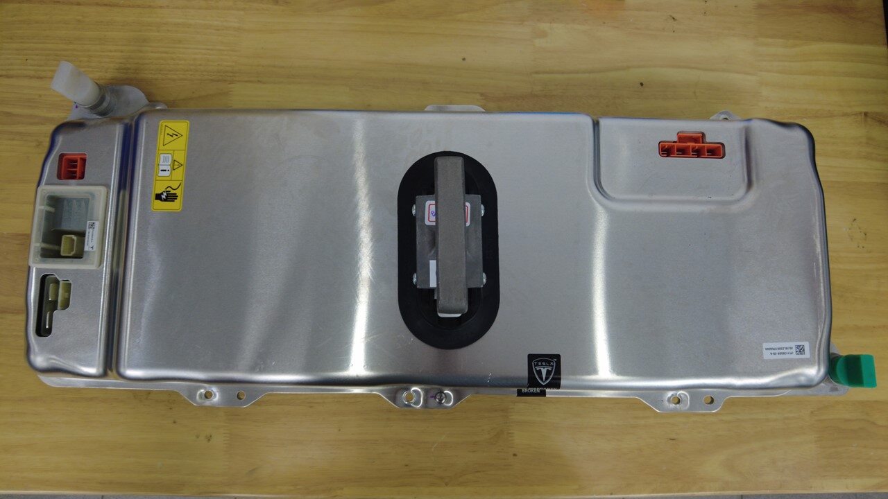
Lift PCS up and out of the ancillary
bay area and remove from vehicle
注Slightly tilt rear of PCS upward then lift out to remove, Inspect any missing insulators under PCS, Install any missing insulators before continuing to next step, Visually inspect area for any coolant residue, Clean with shop towel if necessary
-
Remove suction cups from the old
PCS


安装
-
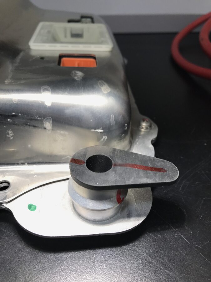
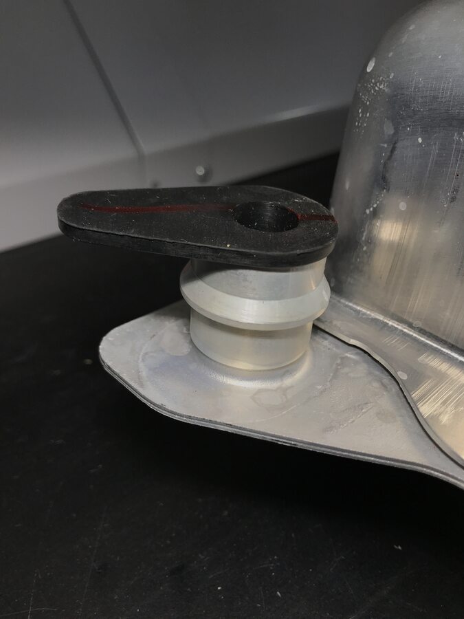
Remove PCS plugs from new PCS
注2x plugs
-
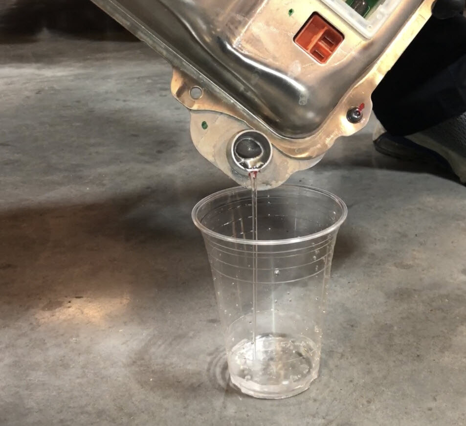
Drain water from new PCS
-
Reinstall plugs on new PCS prior
installing into vehicle
注Clean any water/coolant with absorbent sheets if necessary
-
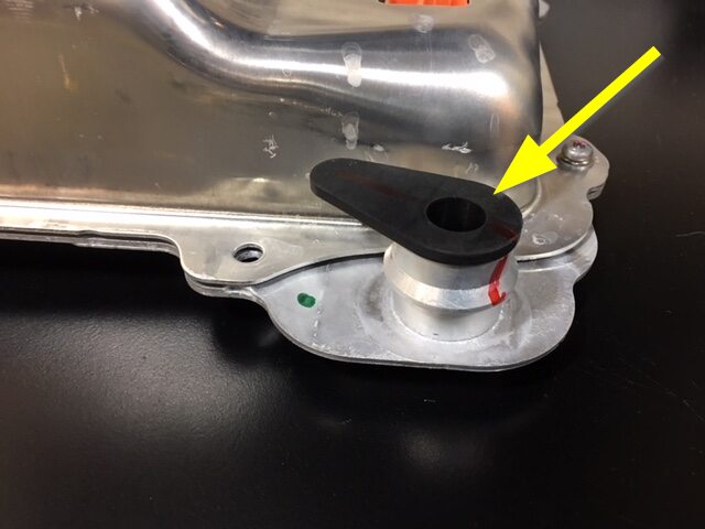
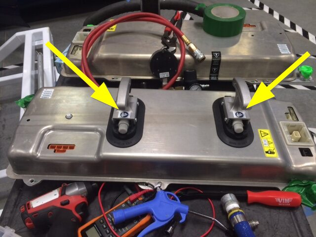
Attach suction cups to PCS
注Continue pressing plunger until red line is no longer visible
-
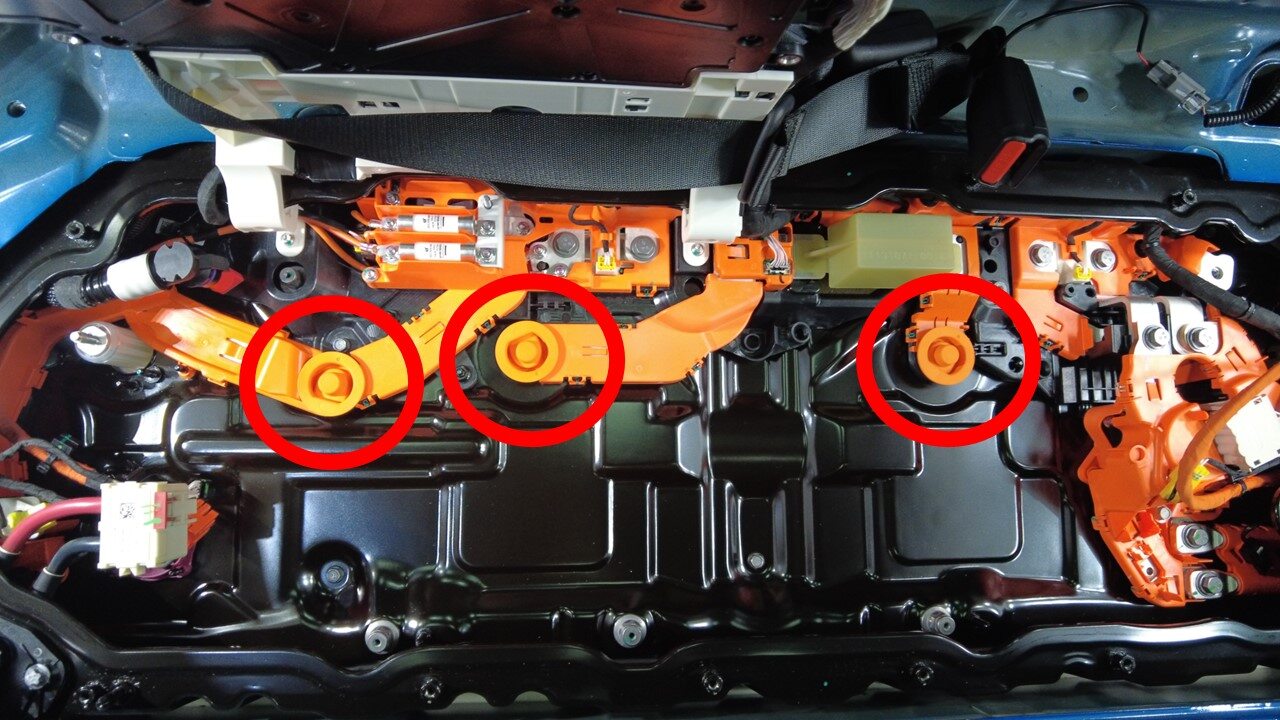
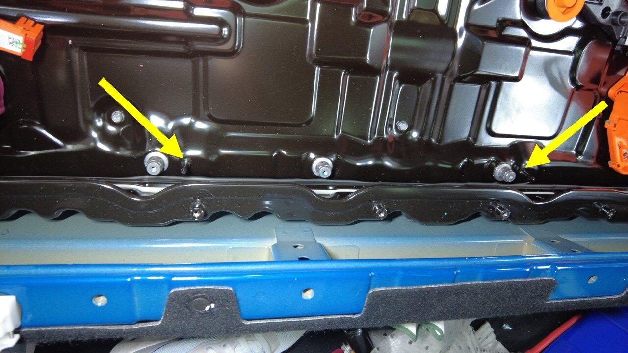
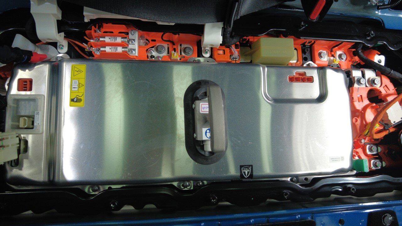
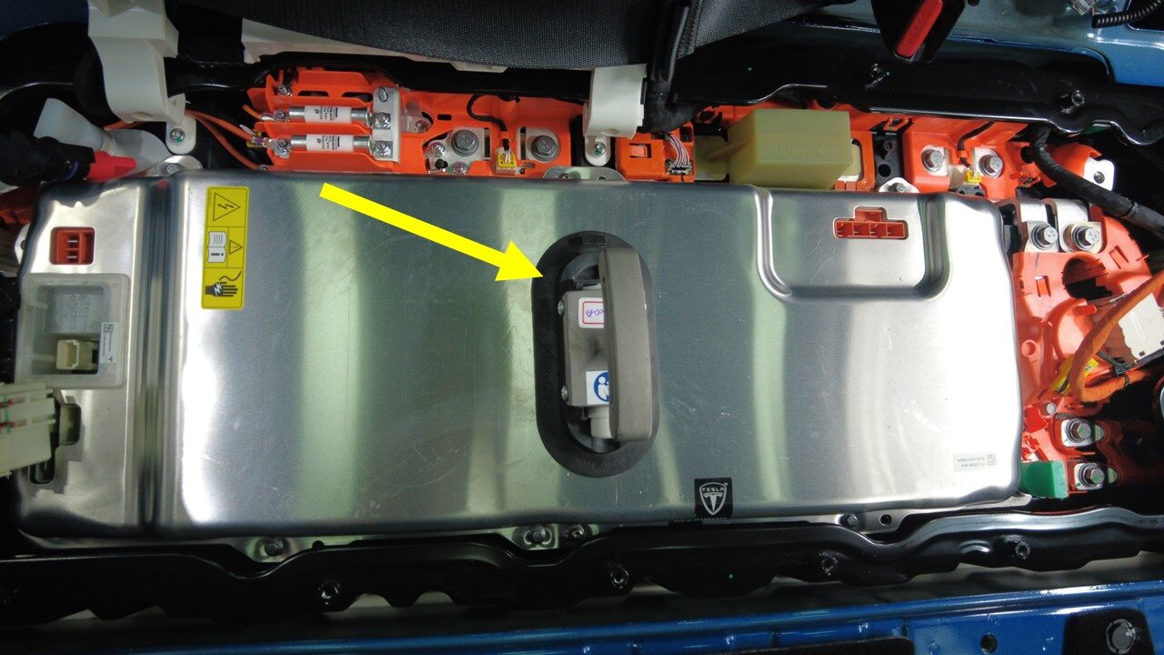
Position the PCS into ancillary
bay
注Ensure all busbar insulators beneath PCS are present, Slightly tilt rear of PCS upward and lower into position, Align datum into PCS holes, Inspect for any coolant residue inside the ancillary bay and clean with absorbent sheets if necessary
-
Remove suction cups from PCS
-
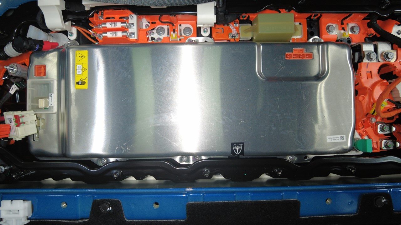
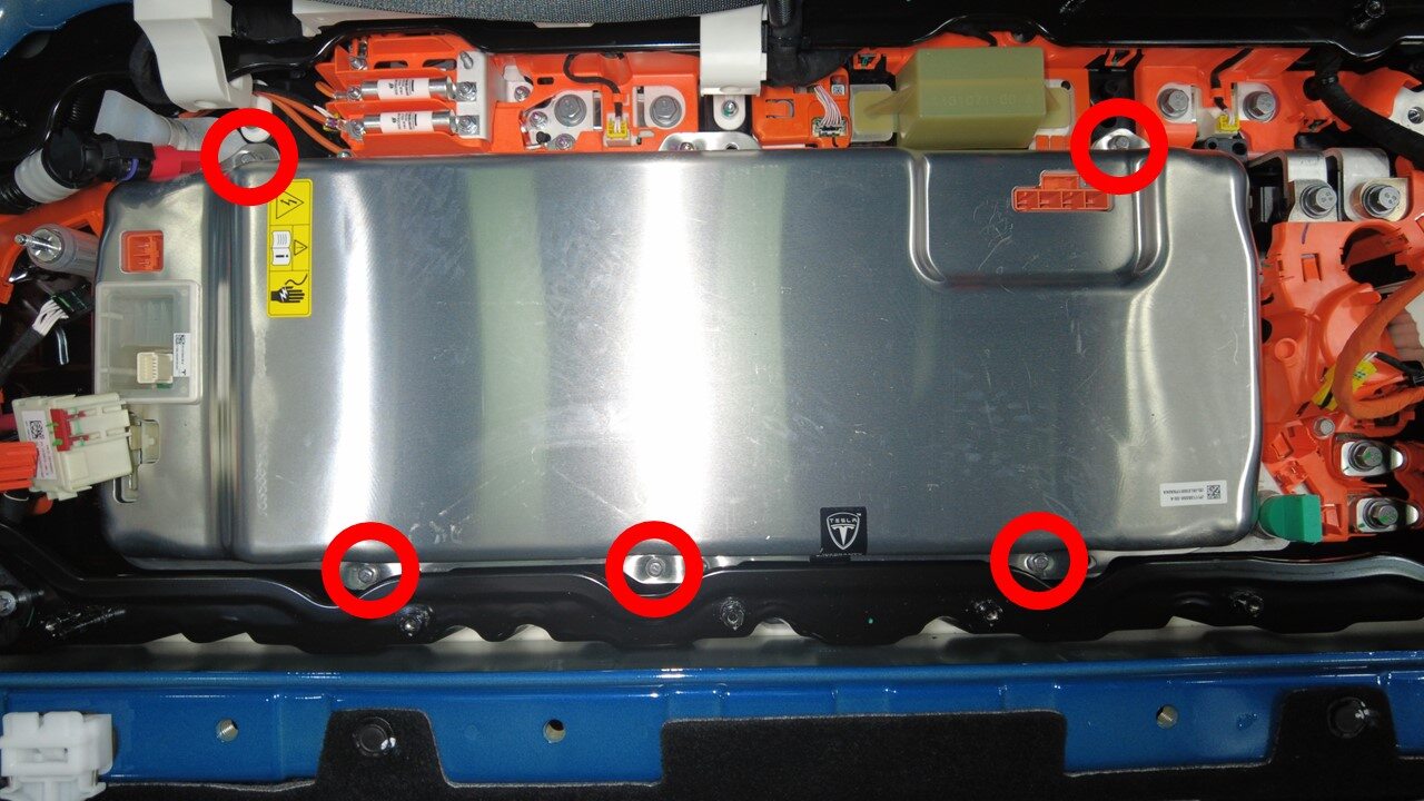
Install bolts securing PCS to HV
battery
注5x bolts, 8mm, 18 Nm
-
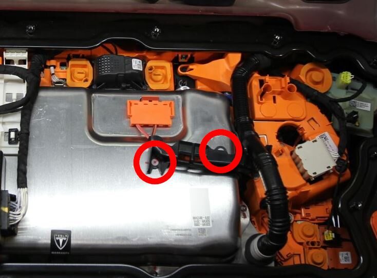
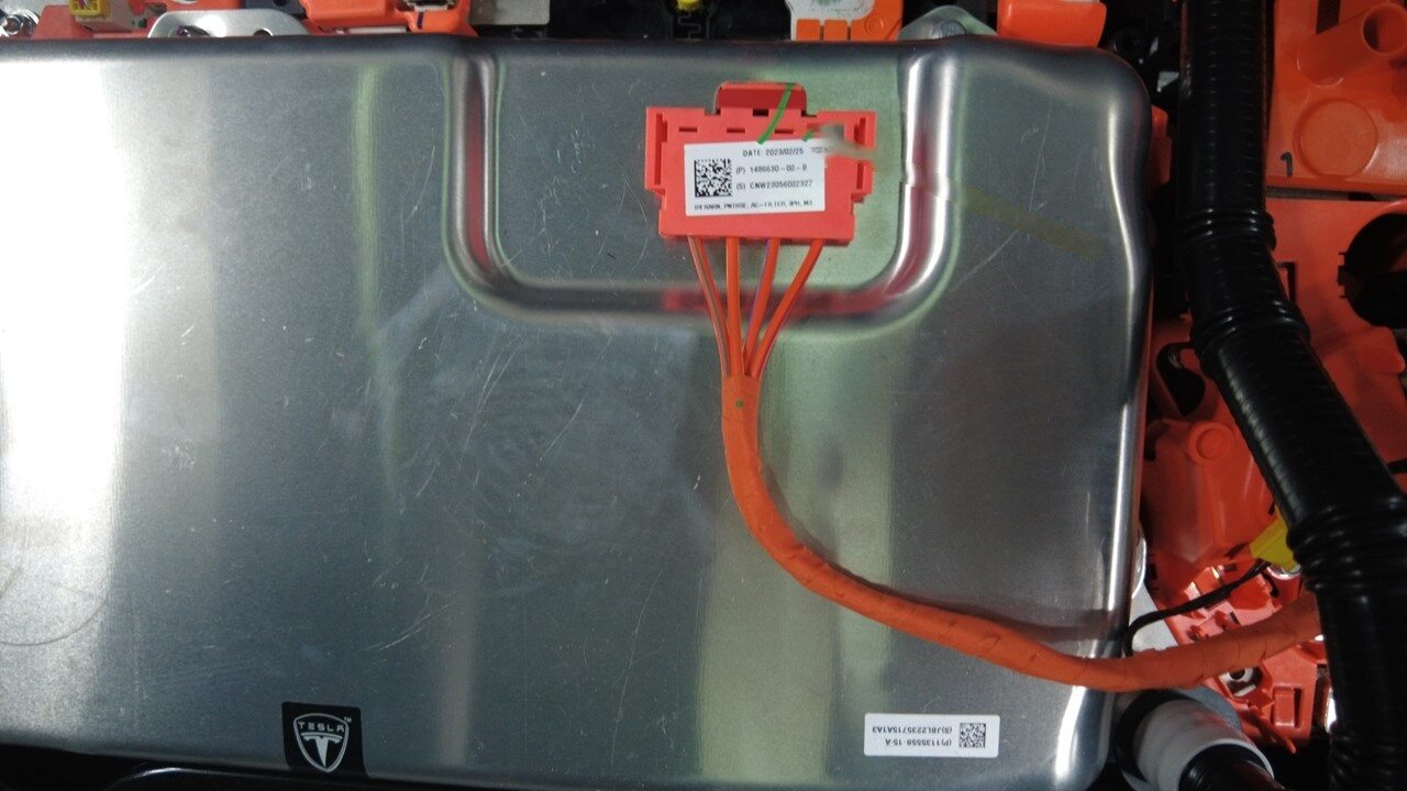
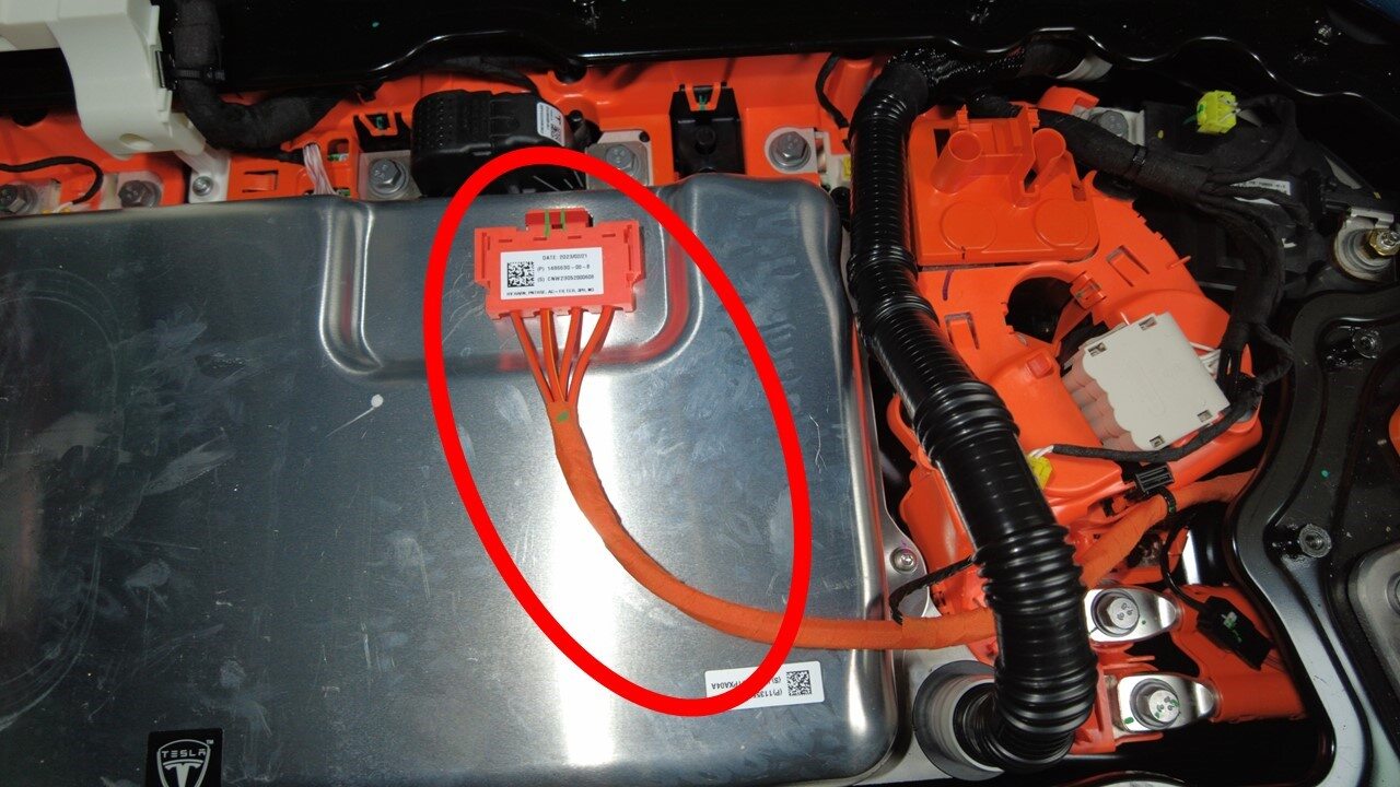
For vehicles that have a 1-Phase charging system: release the clips (x2) that attach
the PCS to fastcharge contactor HV harness to the PCS and set the harness aside.
注There are differences in different regions, depending on having a 1-Phase or 3-Phase charging system: 1-Phase has a wiring harness fixing bracket, 3-Phase comes without this bracket.
-
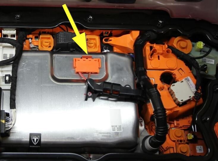
Connect PCS to fastcharge contactor HV
harness connector
注1x connector, Push connector downward then push the locking tab downward to install connector, Make sure the connector is fully seated
-
Connect PCS to DC bus HV
connector
注1x connector, Push connector downward then push the locking tab downward to install connector, Make sure the connector is fully seated
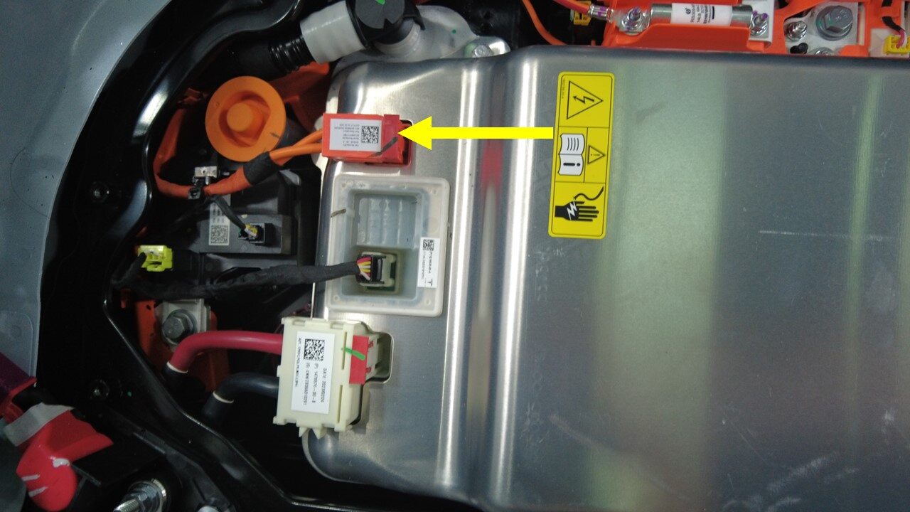
-
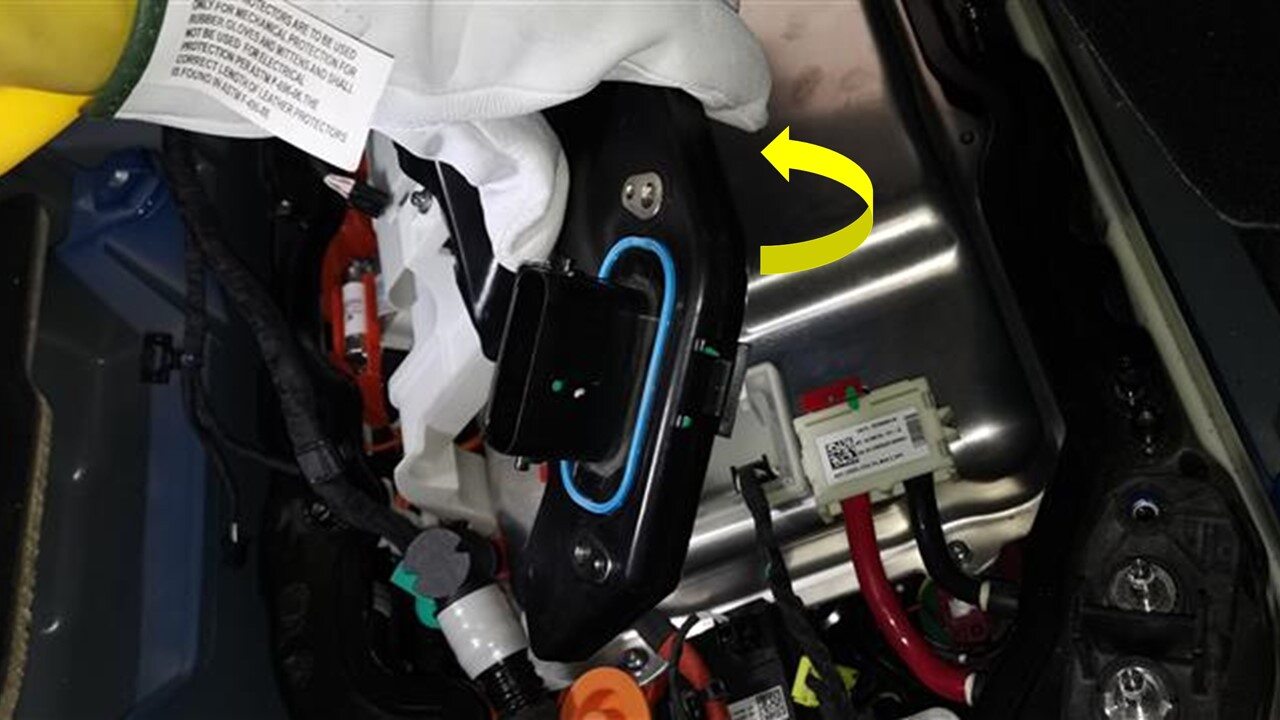
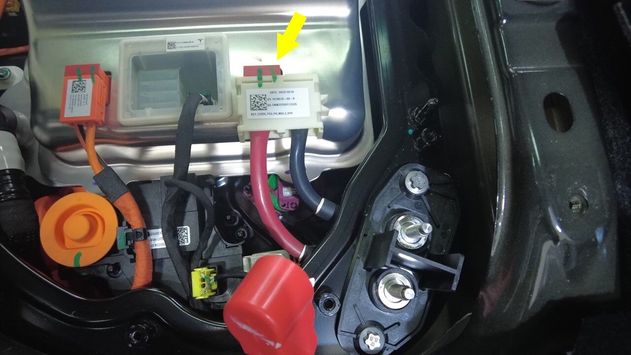
Connect PCS LV connector to PCS
注1x connector, Push connector downward then push the locking tab downward to install connector, Make sure the connector is fully seatedLift the HVC up from the front
-
Connect PCS logic connector to
PCS
注1x connector

-
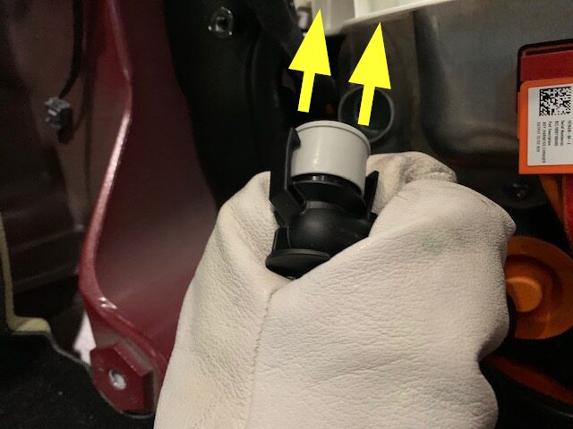
Remove plug from PCS inlet hose
-
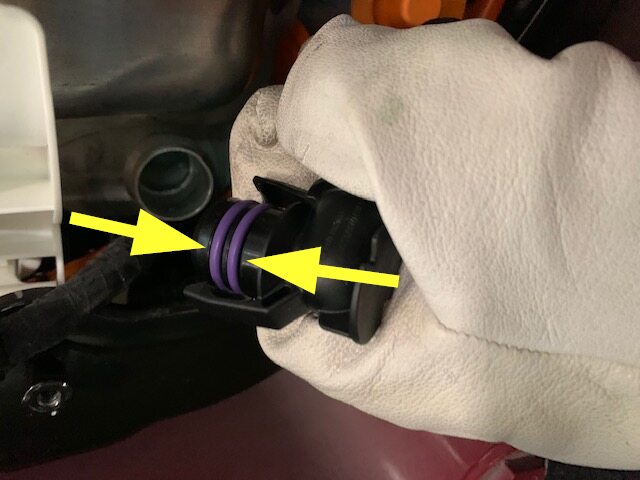
Replace o-rings on PCS inlet
hose
注2x o-rings, Apply light amount of Krytox 203
-
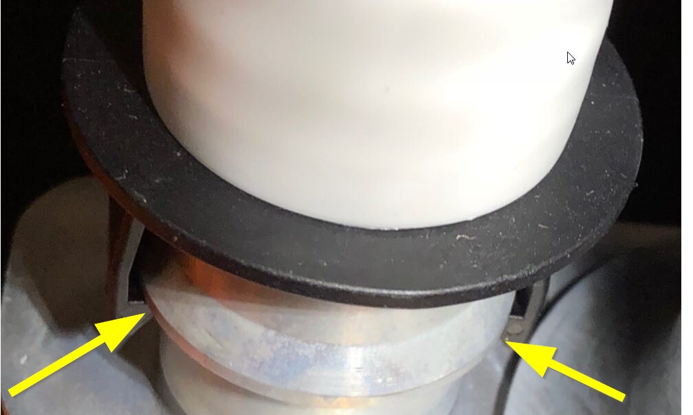
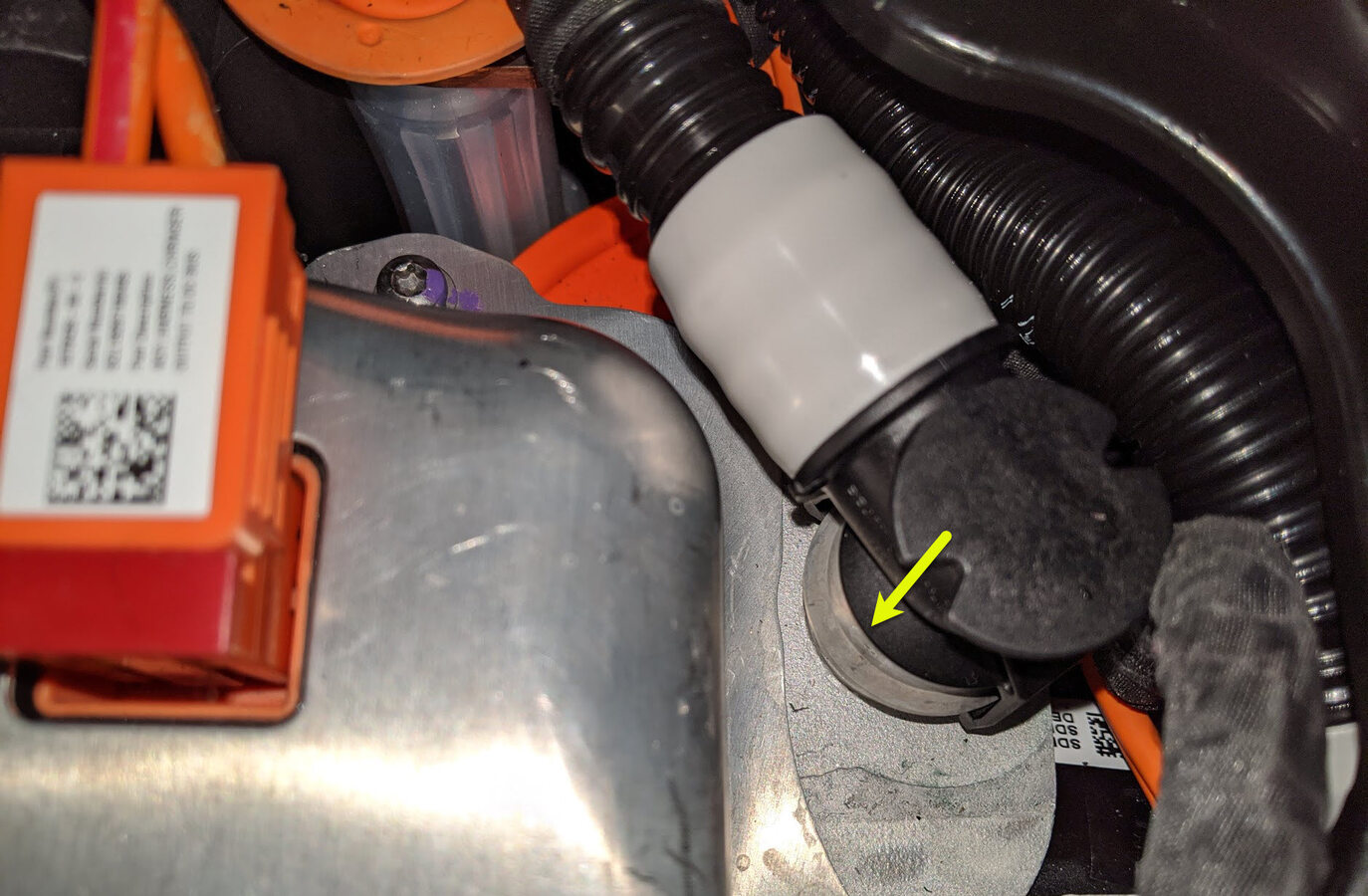
Secure inlet hose to PCS
注1x hose, Place absorbent sheet under hose to catch excess coolant, Caution when installing this hose, it's difficult to align hose to coupling, Use caution not to damage the o-rings, Perform push-pull-push test to make sure coolant hose is fully latched, Then visually verify clip is fully seated
-
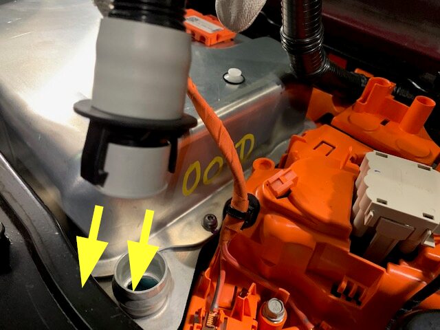
Remove plug from PCS outlet hose
-
Replace o-rings on PCS outlet
hose
注2x o-rings, Apply light amount of Krytox 203
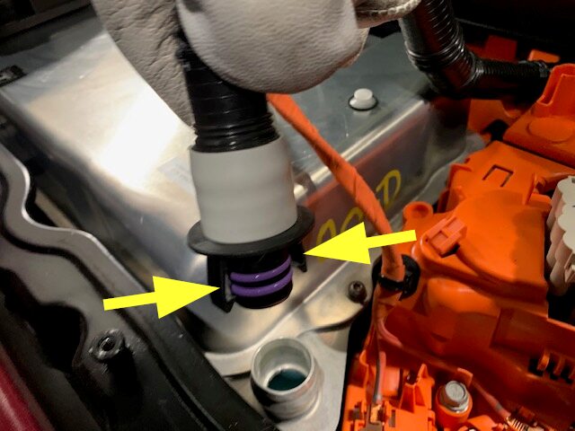
-
Secure PCS outlet hose to PCS
注1x hose, Place absorbent sheet under hose to catch excess coolant, Caution not to damage the o-rings, Perform push-pull-push test to make sure coolant hose is fully latched, Then visually verify clip is fully seated, Visually inspect area for any coolant residue, Clean with shop towel if necessary
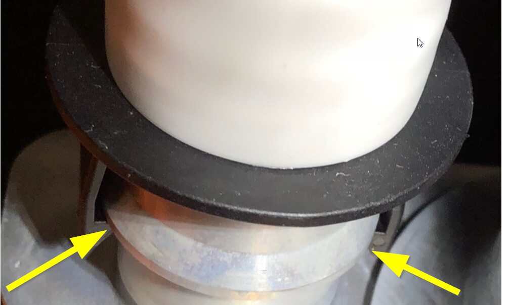
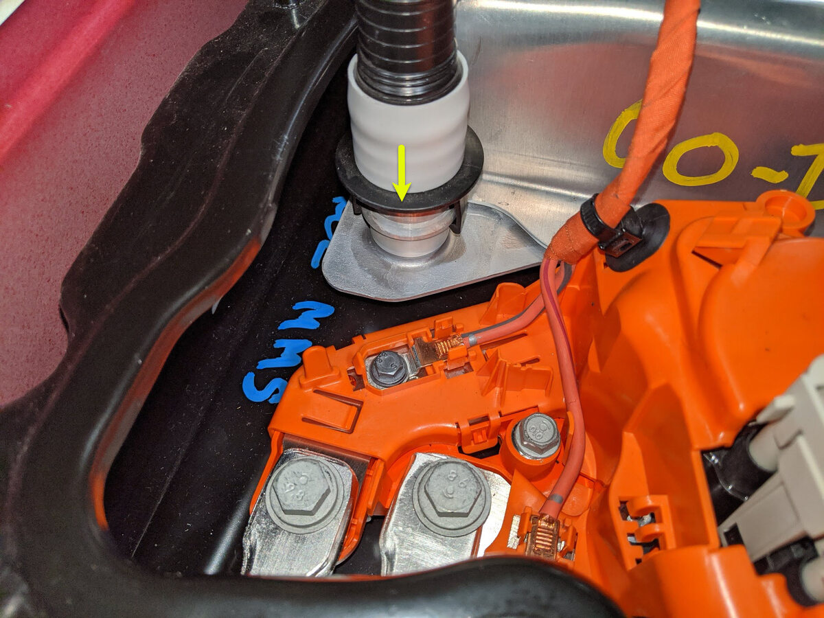
-
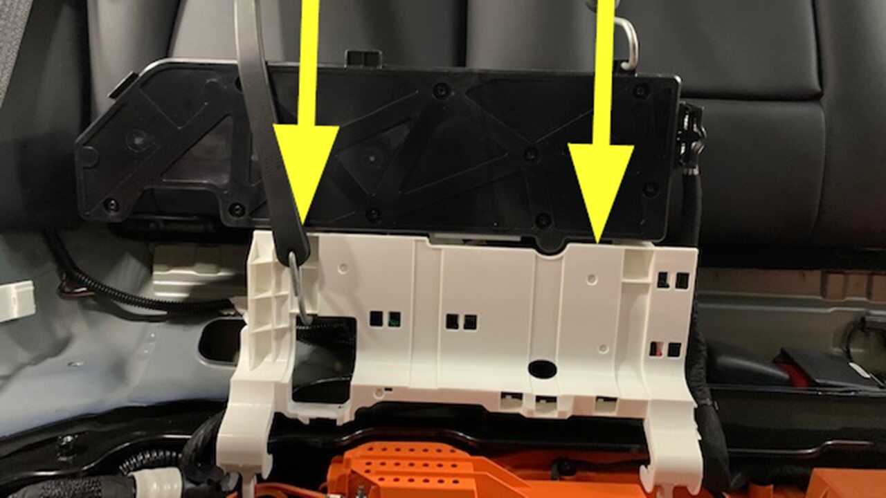
Lay HVC in original position
注Release bungee from back of headrest
-
Remove HV insulating gloves

-
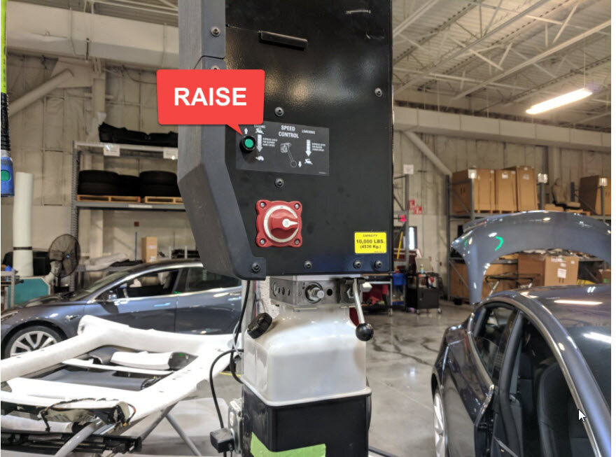
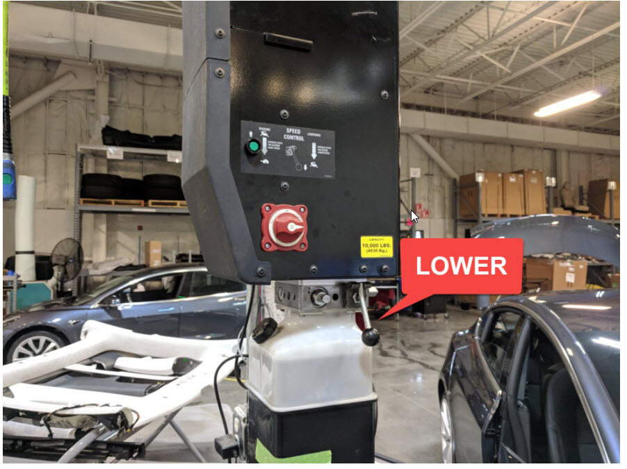
Raise vehicle fully and lower lift
onto locks
注Set vehicle to comfortable working height, Make sure there's an audible click of locks on both sides before lowering, otherwise vehicle may tilt to side
-
Position coolant drain container
underneath LH rear of HV battery
-
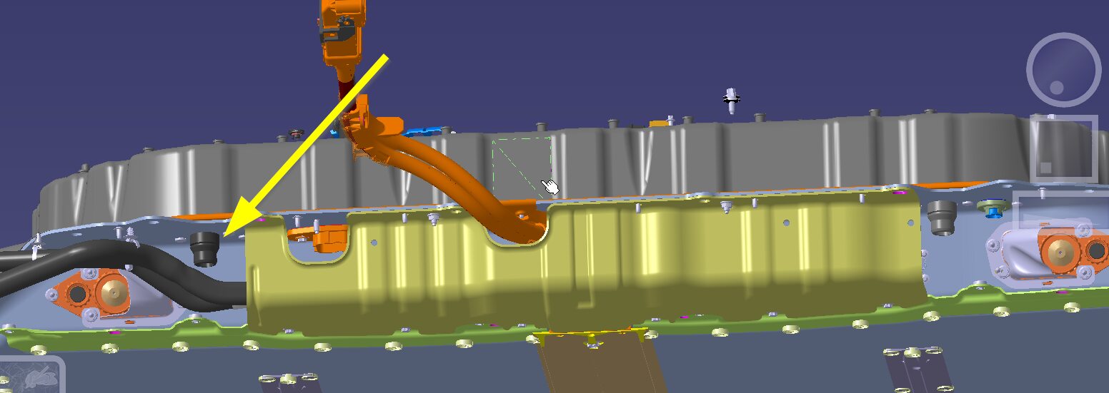
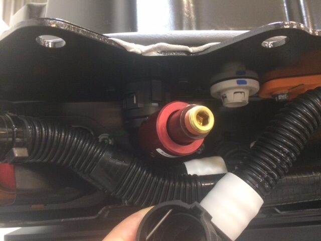
Install coolant pressure test plug
adapter to PCS outlet hose coupling
注Remove plug from coupling, Make sure the locking tab is fully seated
-
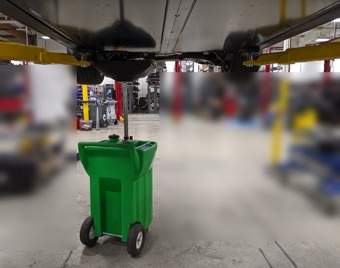
Position coolant drain container
underneath RH rear of vehicle
-
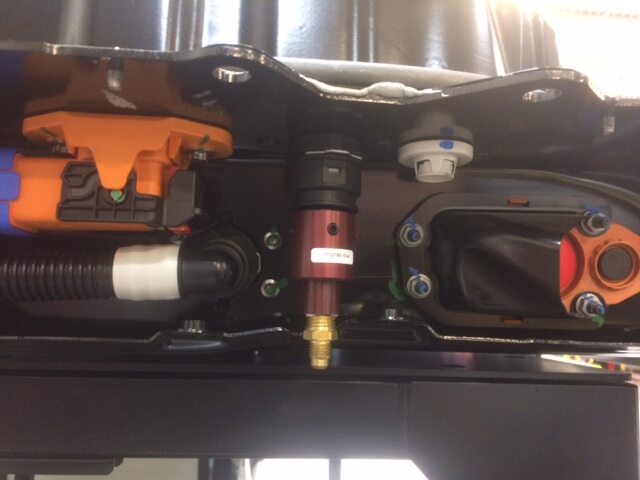
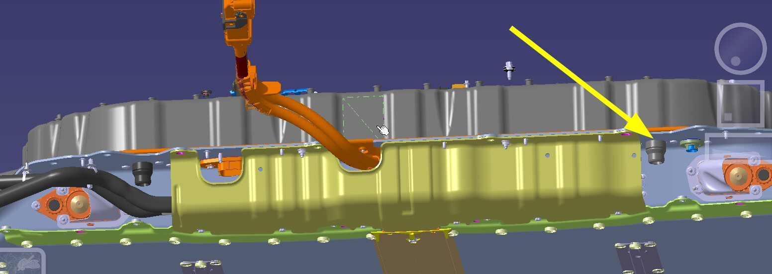
Install coolant pressure adapter to
PCS inlet hose coupling
注Remove plug from coupling, Make sure the locking tab is fully seated
-
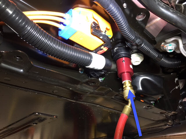
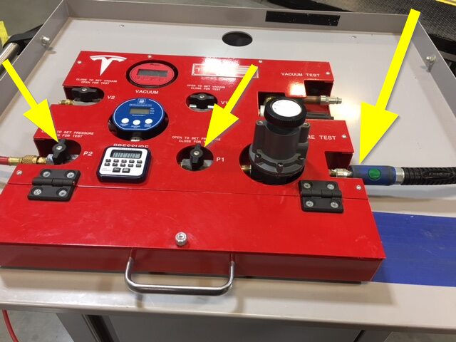
Attach coolant pressure tester to
pressure fitting adapter
-
Attach coolant pressure tester to
compressed air line
注Make sure valves are closed on pressure regulator
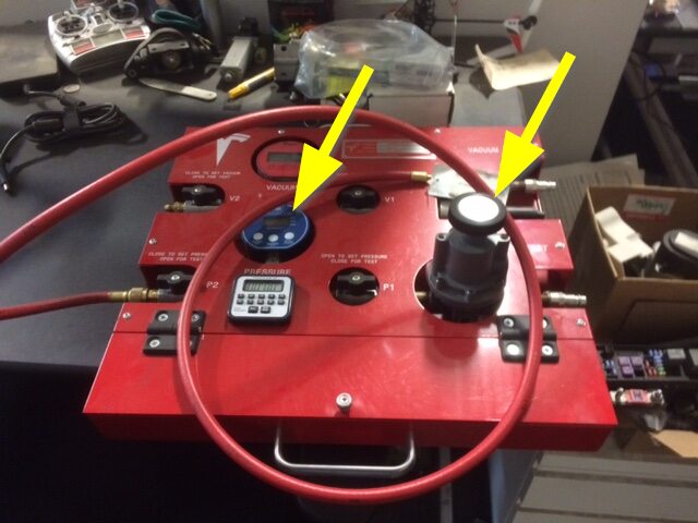
-
Set pressure regulator to specified
pressure value
注Set pressure to 50 psi
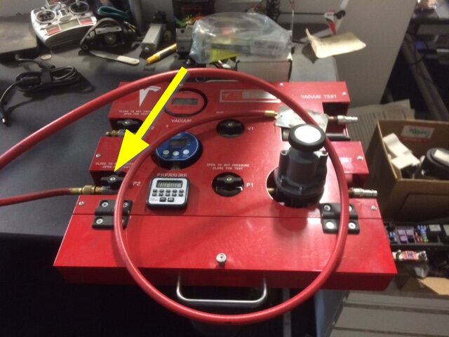
-
Slowly open valve on pressure
regulator and allow pressure to reach specification
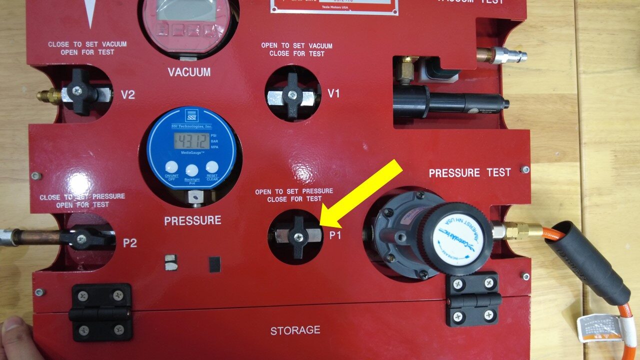
-
Close the valve and let pressure
settle
注Wait 2 minutes for pressure to settle, Record the reading
-
Perform the coolant pressure leak
test
注Wait for another 4 minutes and record the reading. Max delta 0.35 psi. Check coolant hose to see if it is fully seated or not if pressure test fails

-
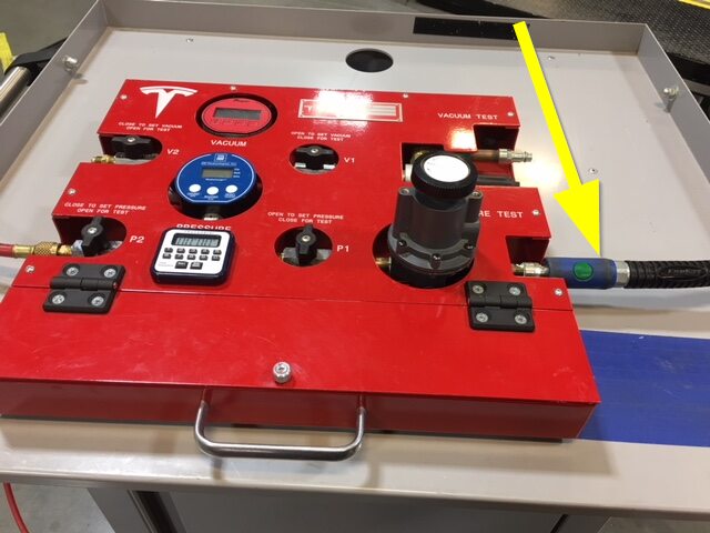
Disconnect compressed air from coolant
pressure tester
-
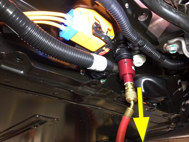
Remove pressure fitting adapter from
coolant pressure tester
-
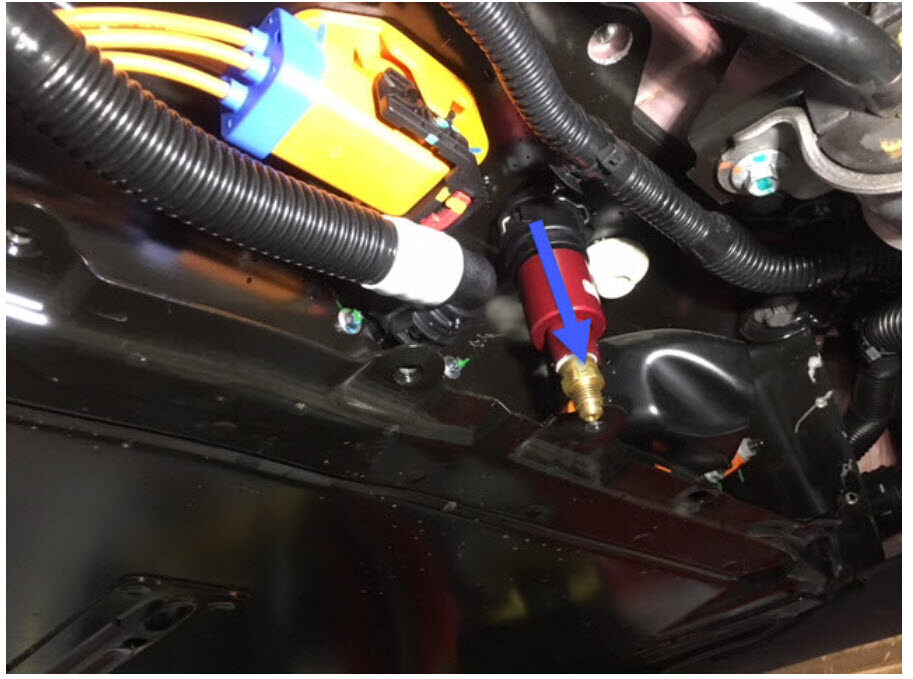
Remove coolant pressure tester from
PCS inlet hose coupling
-
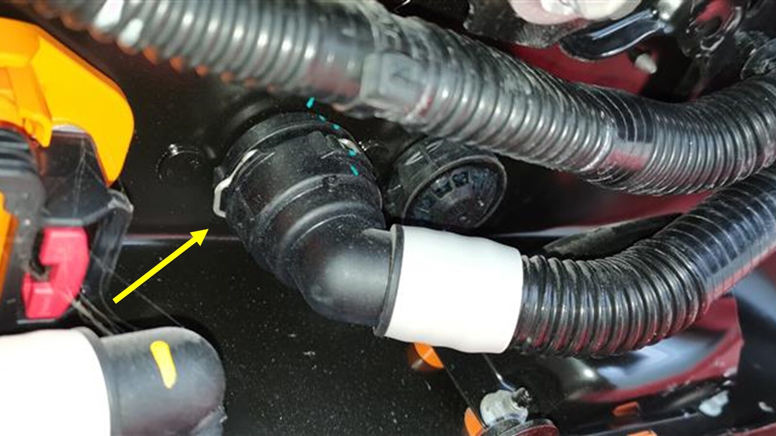
Connect rear PT supply hose to rear of
HV battery
注1x spring clip, Remove plug from rear PT supply hose, Make sure the locking tab is fully seated
-
Remove coolant pressure test plug
adapter from PCS outlet hose coupling
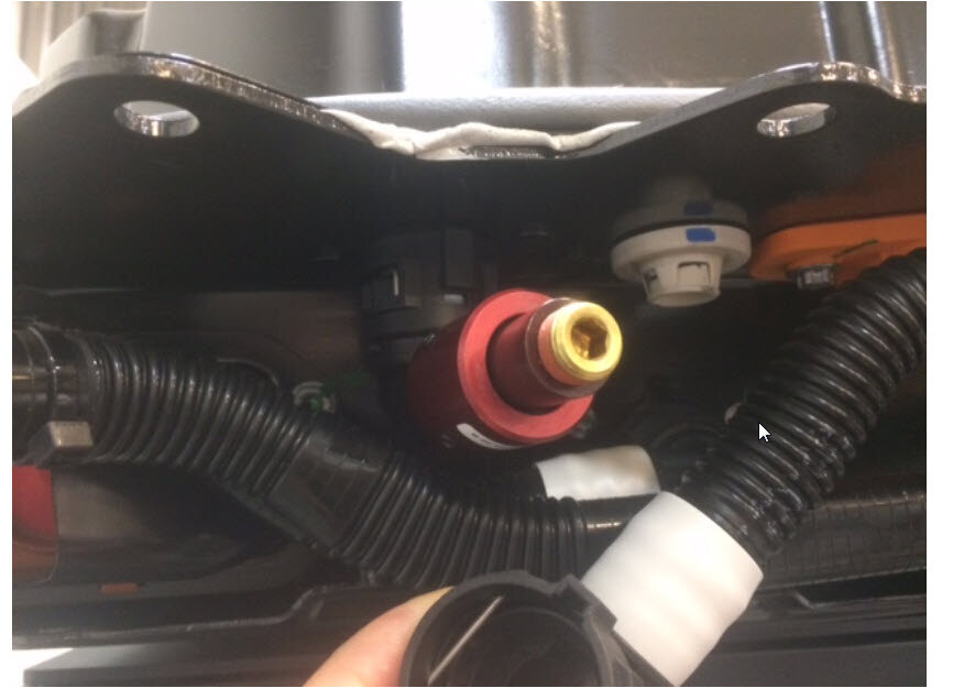
-
Connect RDU inverter inlet hose to
rear of HV battery
注1x spring clip, Remove plug from rear PT supply hose, Make sure the locking tab is fully seated
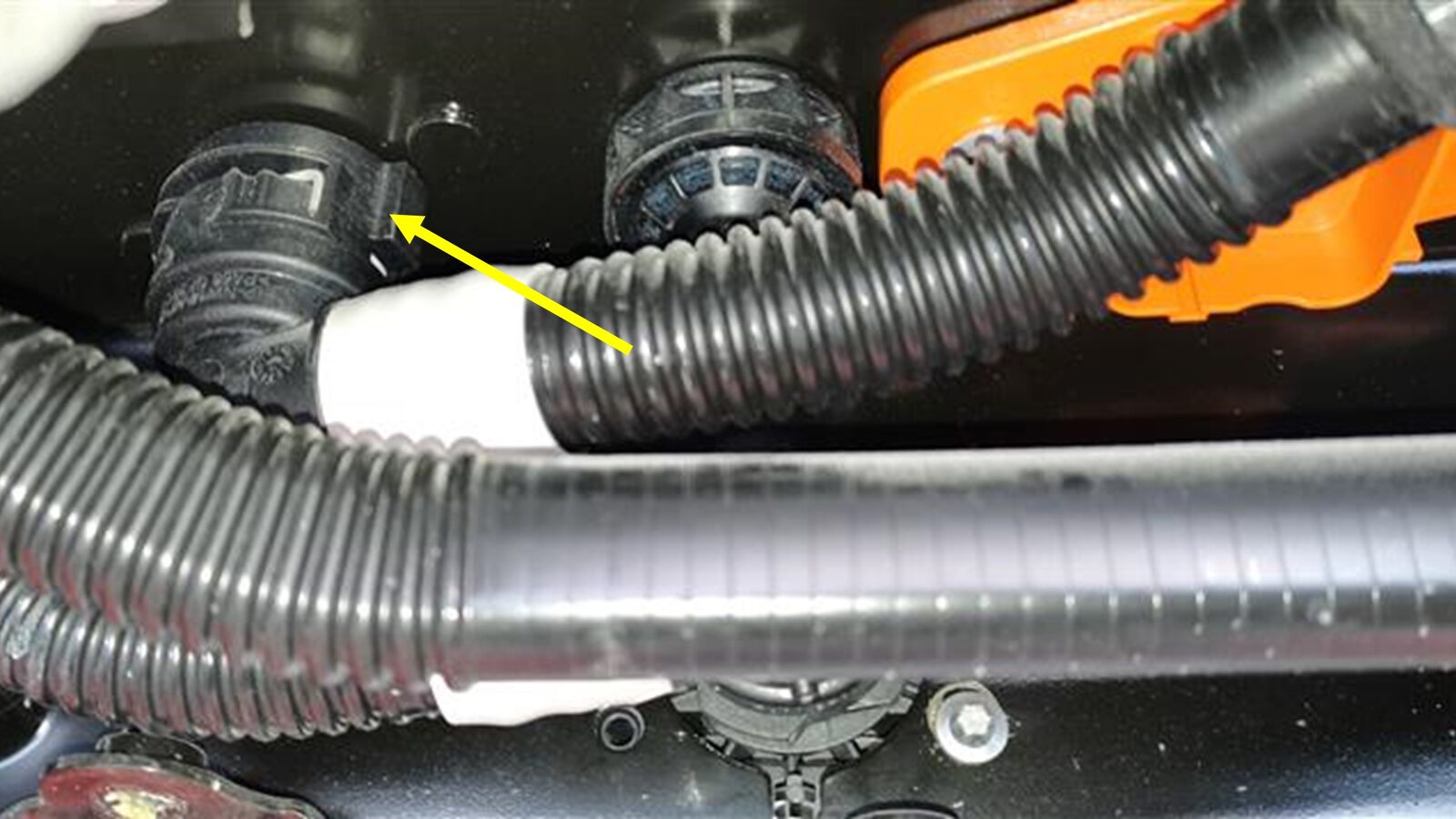
-
Remove coolant drain container from
underneath vehicle
-
Position HV battery rear skid plate
enclosure onto HV battery for installation
注Recommend assistance if needed
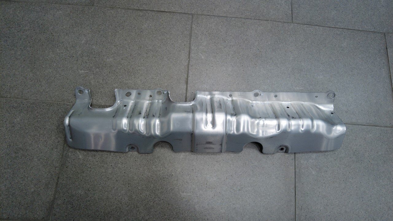
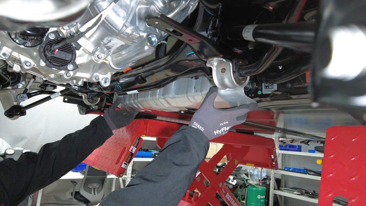
-
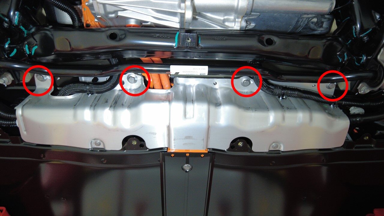
Install upper bolts securing HV
battery rear skid plate enclosure hand tight
注4x bolts, 13mm, 35 Nm, Torque at later step
-
Install upper nut securing HV battery
rear skid plate enclosure hand tight
注1x nut, 10mm, 13 Nm, Torque at later step

-
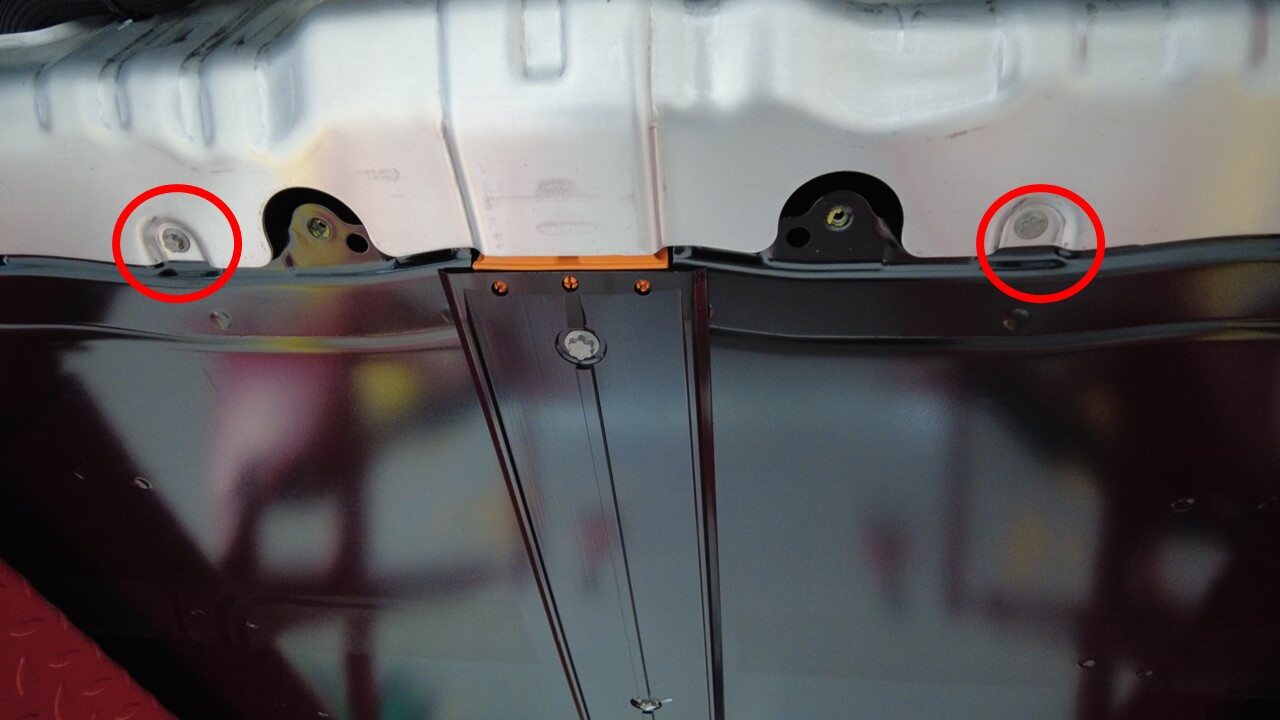
Install lower bolts securing HV
battery rear skid plate enclosure
注2x bolts, EP10, 13 Nm, Earlier vins may be equipped with additional bolts
-
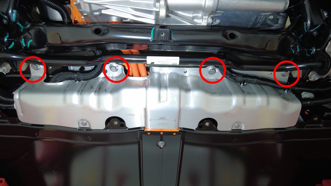
Torque bolts securing HV battery rear
skid plate enclosure to vehicle
注4x bolts, 13mm, 35 Nm
-
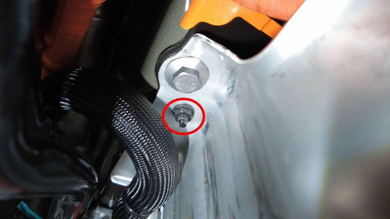
Torque upper nut securing HV battery
rear skid plate enclosure
注1x nut, 10mm, 13 Nm
-
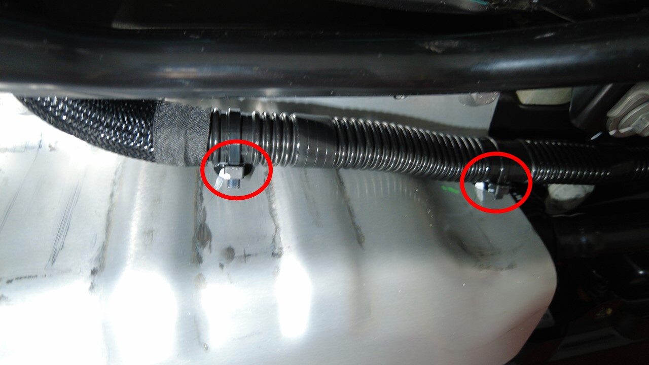
Install RH side hose clips to HV
battery rear skid plate enclosure
注2x fir tree clips
-
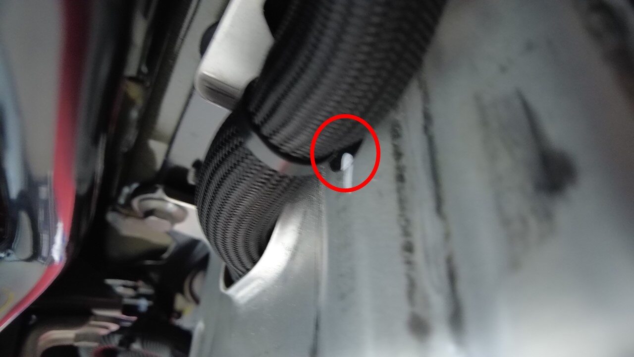
Install LH side hose clip to HV
battery rear skid plate enclosure
注1x clip
-
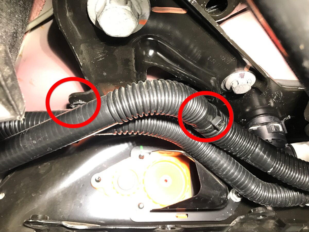
Install clips securing coolant hoses
to LH shear plate
注2x fir tree clips
-
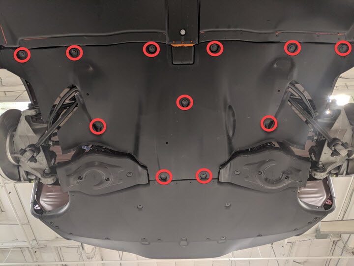
lnstall rear aero shield
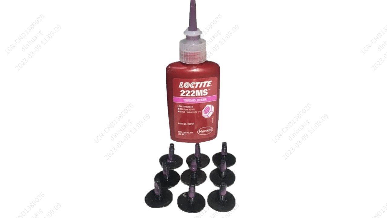
注11x bolts, 10mm, 5 Nm, Apply Loctite 222 onto rear aero shield bolts
-
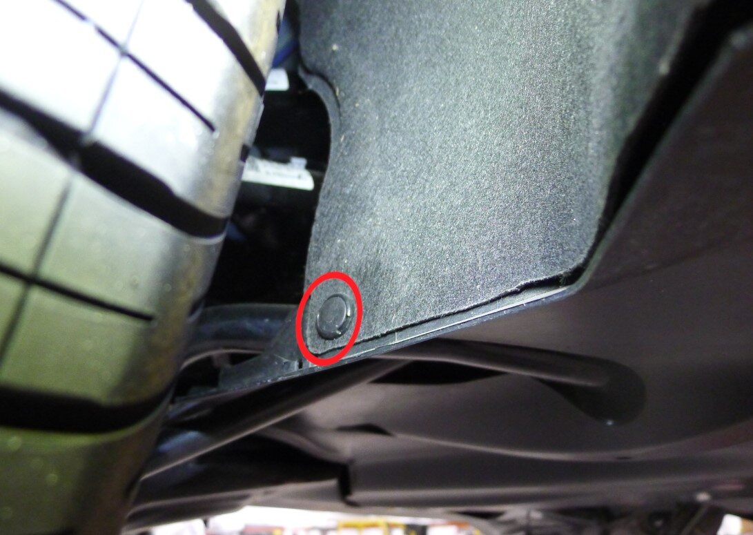
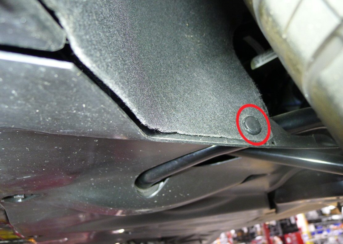
Install LH and RH clips securing rear
aero shield to wheel house liner
注2x clips
-
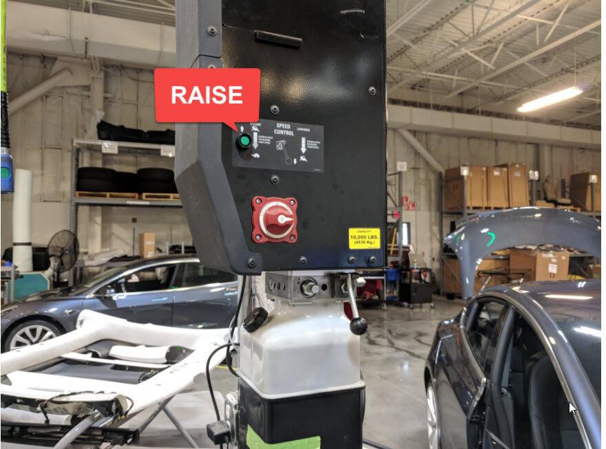
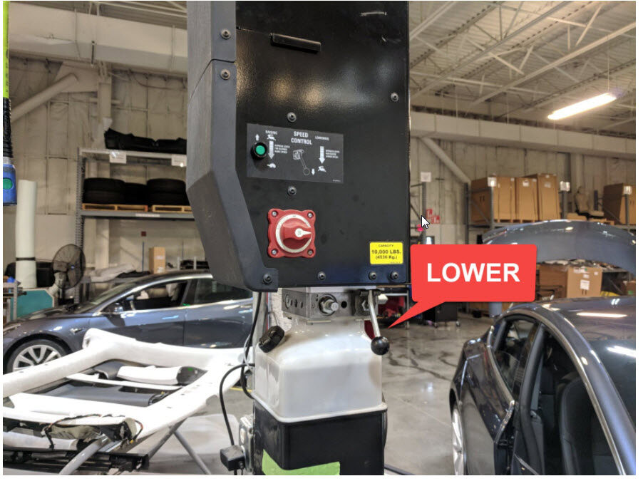
Lower vehicle fully
注Raise lift off locks, then hold lock release lever to keep locks free while vehicle is lowered

-
Inspect HV insulating gloves
注Check gloves for damage prior to use, Refer to service document TN-15-92-003 R1, for information on inspecting HV gloves. https://service.teslamotors.com/protected-doc/ServiceBulletins/External/TN/TN-15-92-003_High_Voltage_Awareness_Care_Points_R4.pdf
-
Put on HV insulating gloves and
leather over gloves
注Make sure to wear Electrical Protective Gloves any time Hioki tester is used
-
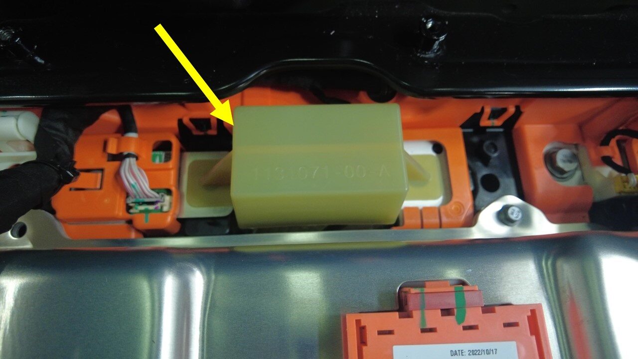
Remove pyro disconnect dummy
-
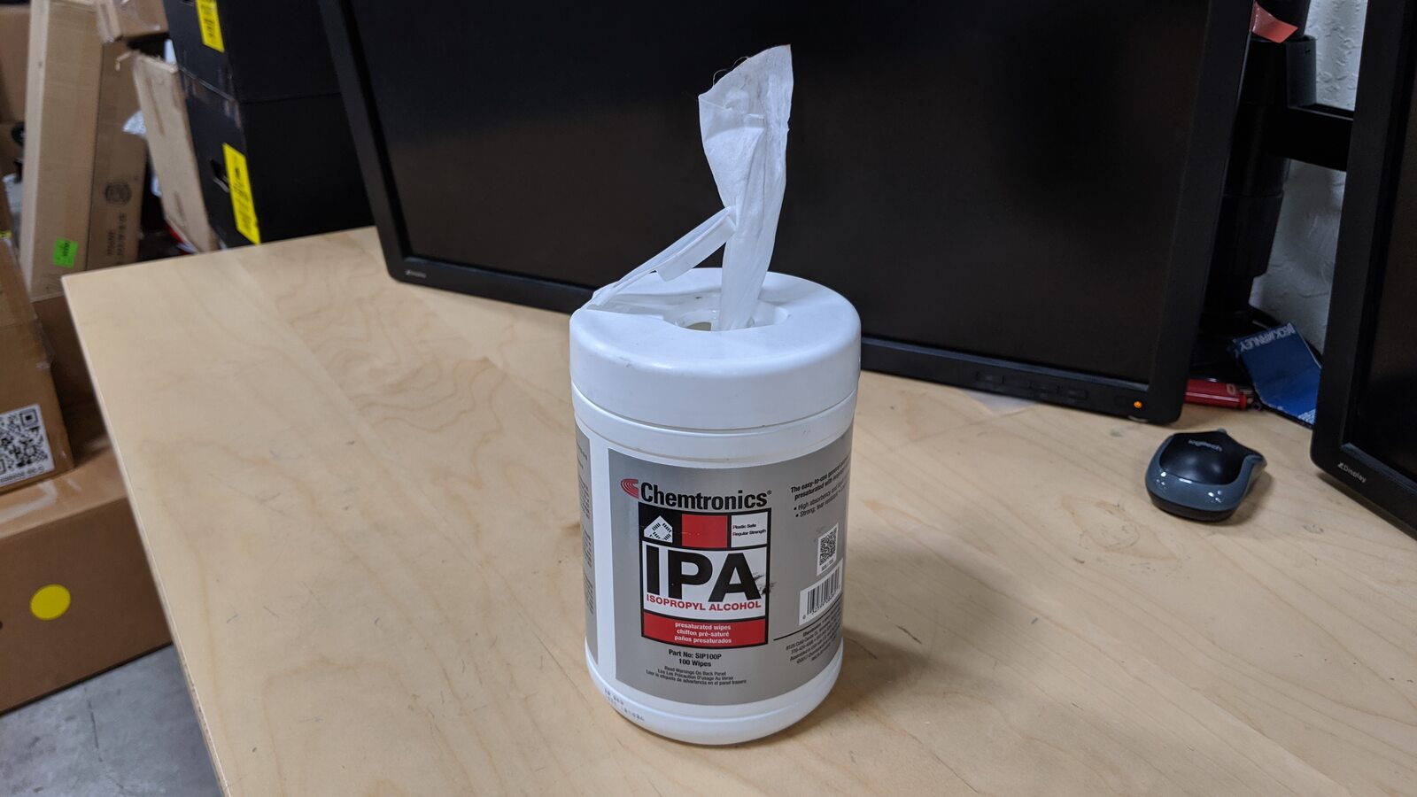
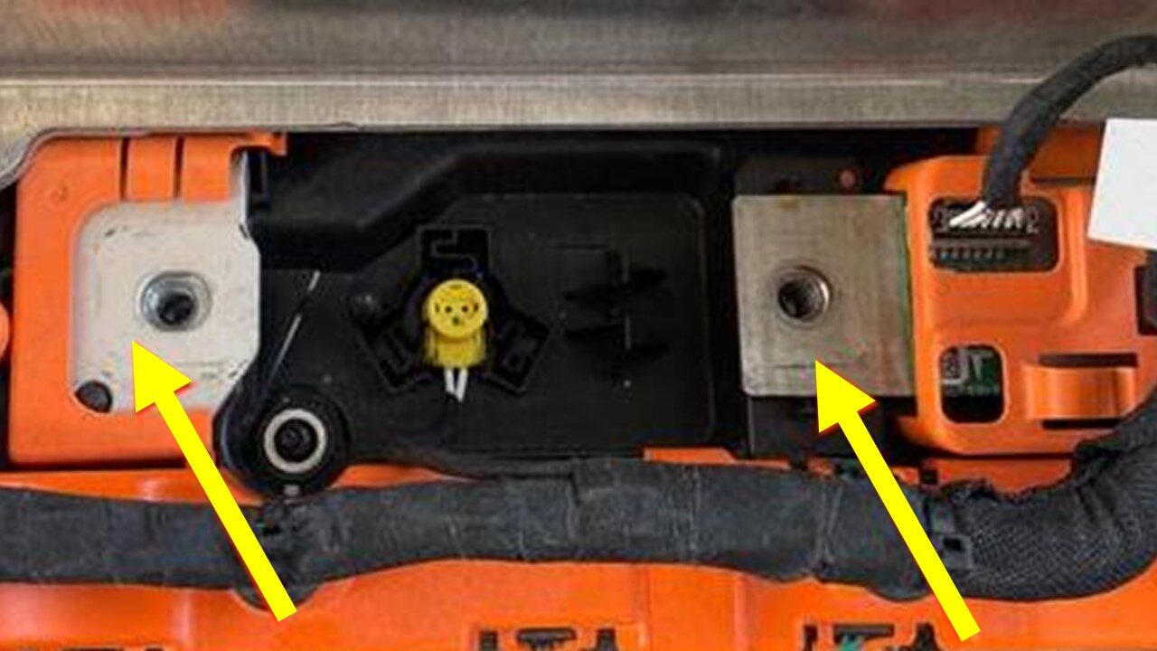
Clean mating surfaces
注Allow to 1 minute dry time,Use an IPA wipe to clean the HV mating surfaces of the shunt, busbar, and the pyrotechnic battery disconnect
-
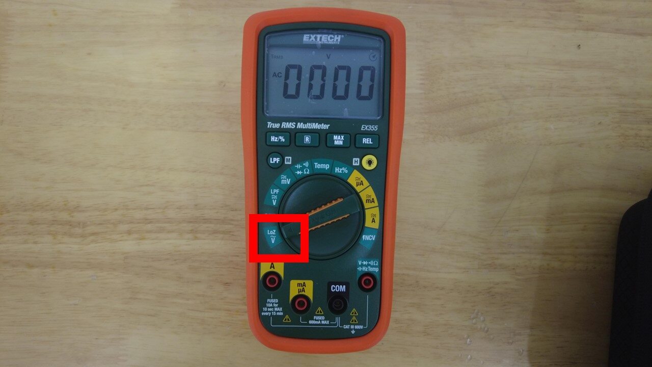
Set multimeter to "LoZ" (low
impedance) mode
-
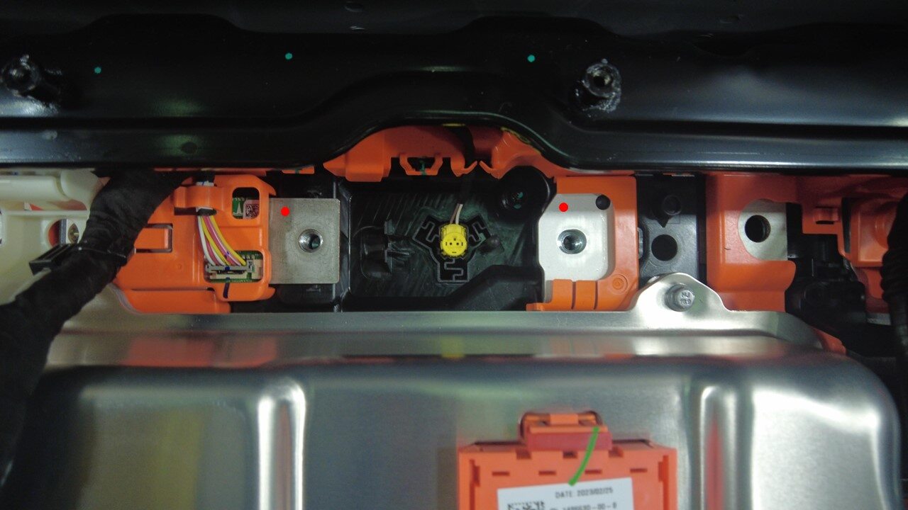
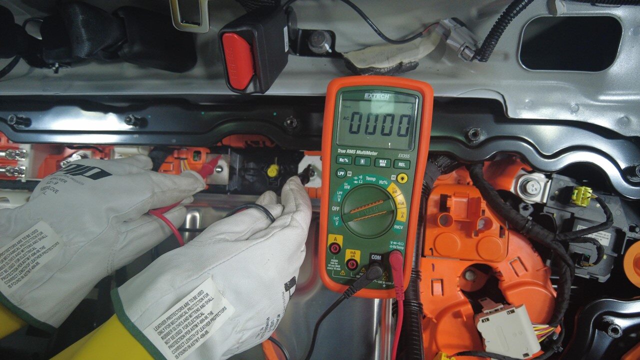
Measure voltage between busbar and
shunt
注While still measuring the voltage, have an assistant position the pyrotechnic battery disconnect into the HV battery for installation. Make sure to align the pins of the connector with the new pyrotechnic battery disconnect, and then press the pyrotechnic battery disconnect down onto the busbars
-
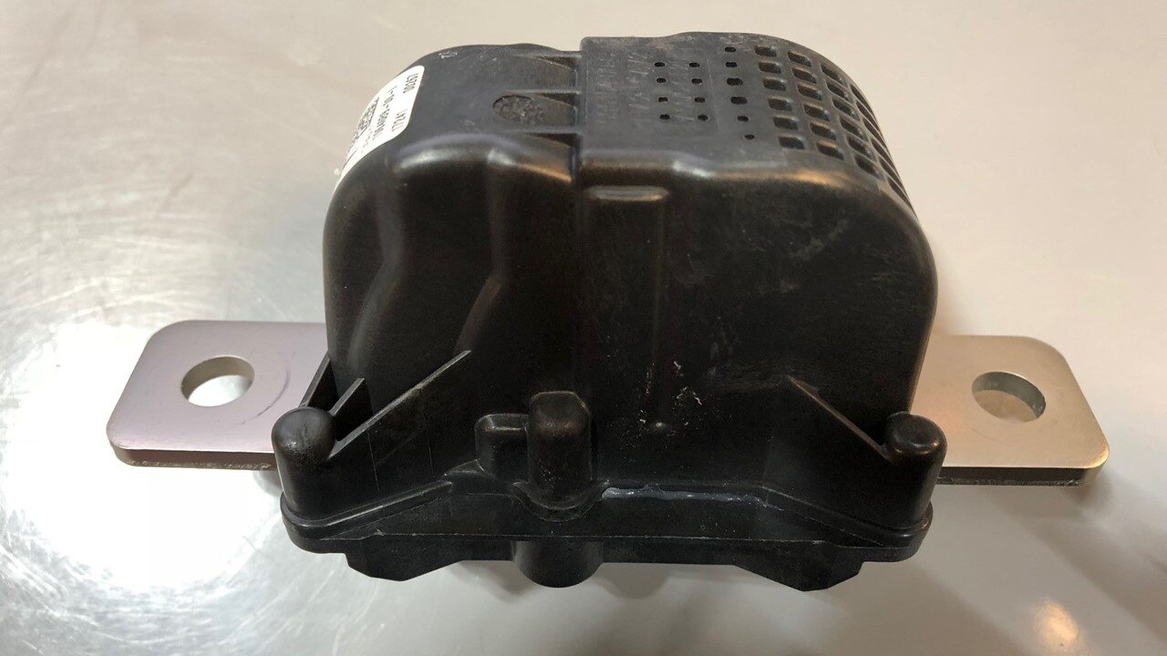
Position pyro disconnect to the
ancillary bay for installation
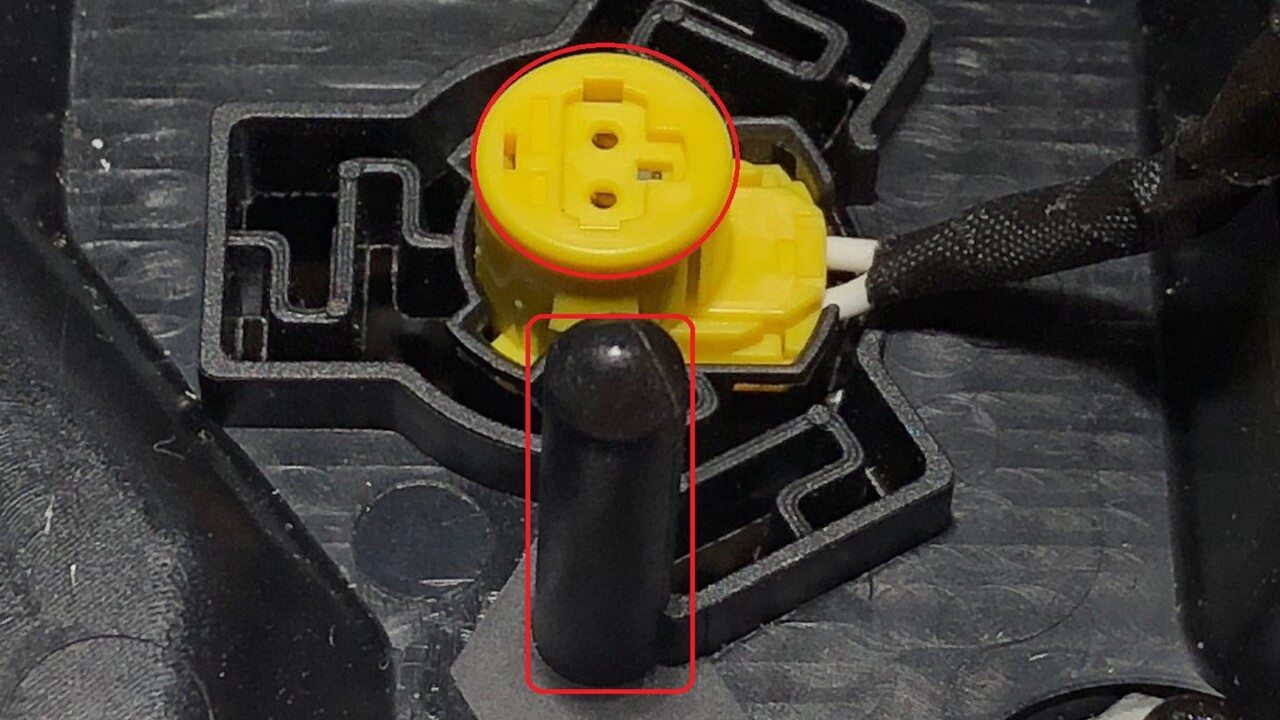
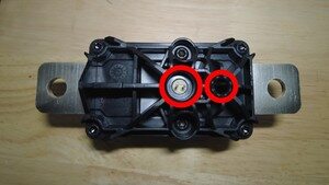
注1x connector, Make sure to align the 2 pins with pyro disconnect, The pyro disconnect can only be installed one way
-
Install bolts securing pyro disconnect
to the ancillary bay
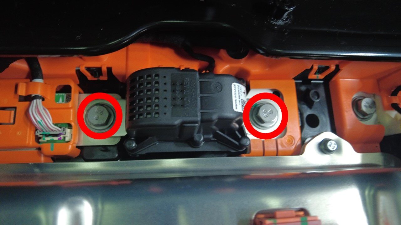
注2x patch bolts, 13mm, 9 Nm
-
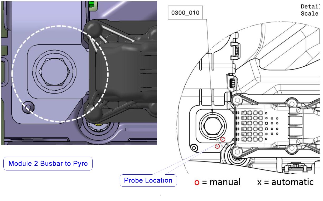
Measure resistance from module 2
busbar to pyro disconnect
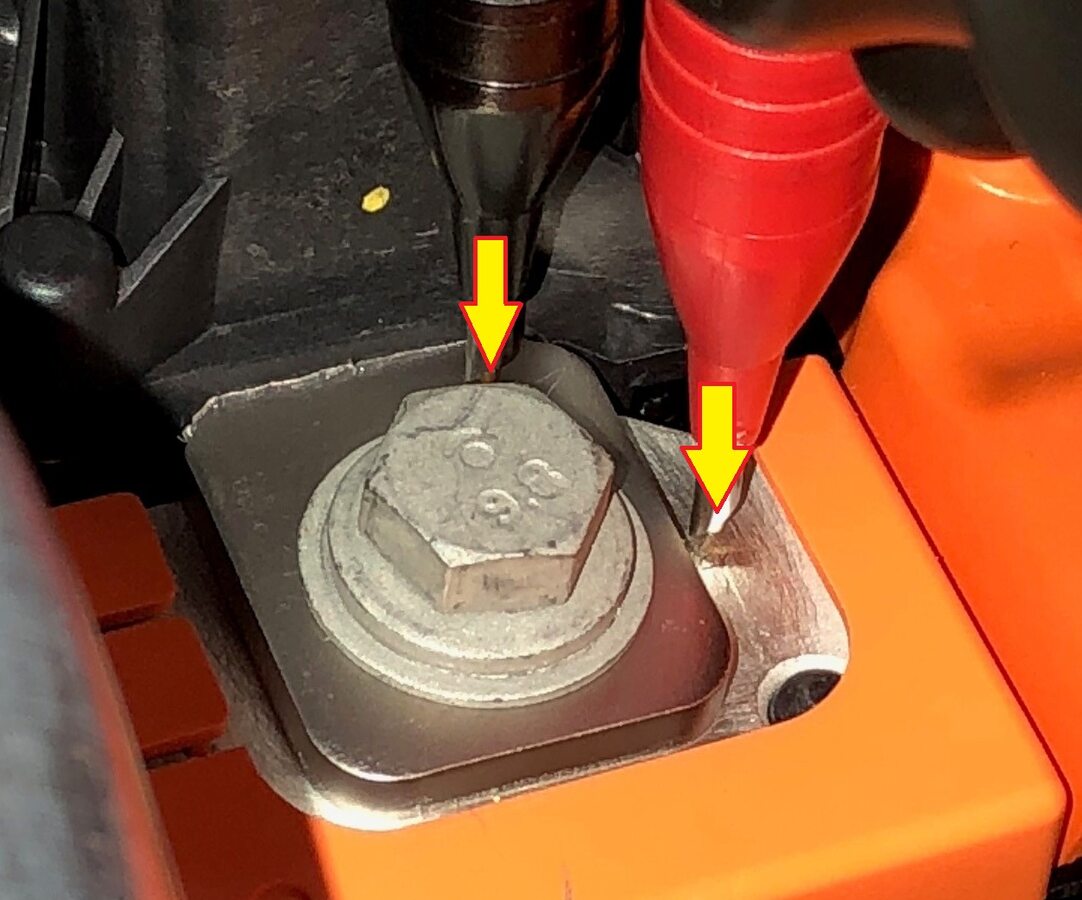
注1x HV joint, 48_xD835__xDF07_Ω or less, Perform zero adjust to Hioki meter prior to testing
-
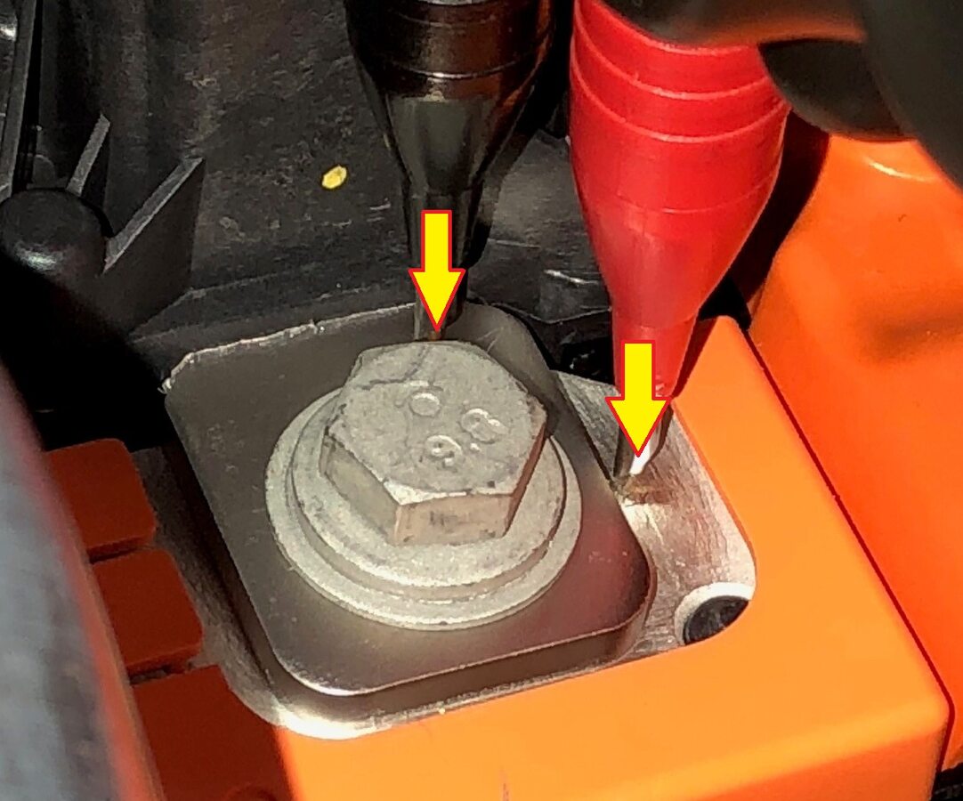
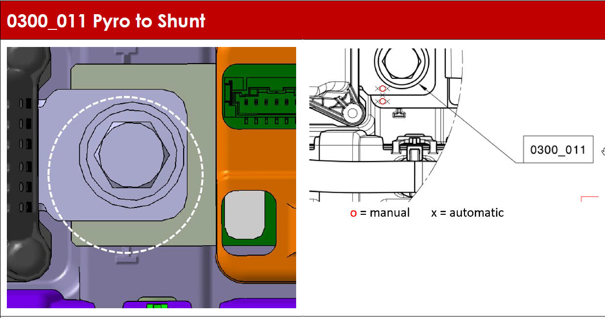
Measure resistance from pyro
disconnect to shunt
注1x HV joint, 33_xD835__xDF07_Ω or less, Perform zero adjust to Hioki meter prior to testing
-
Remove service insulator kit
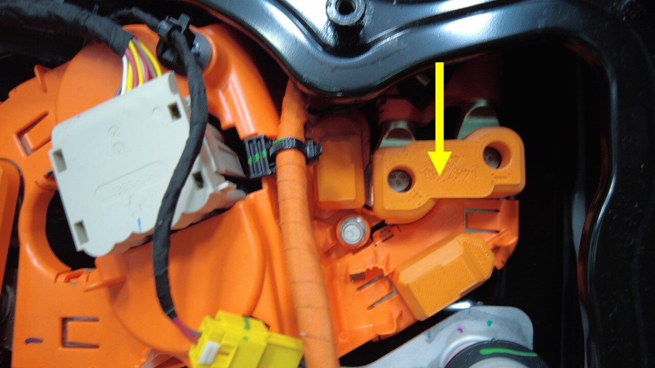
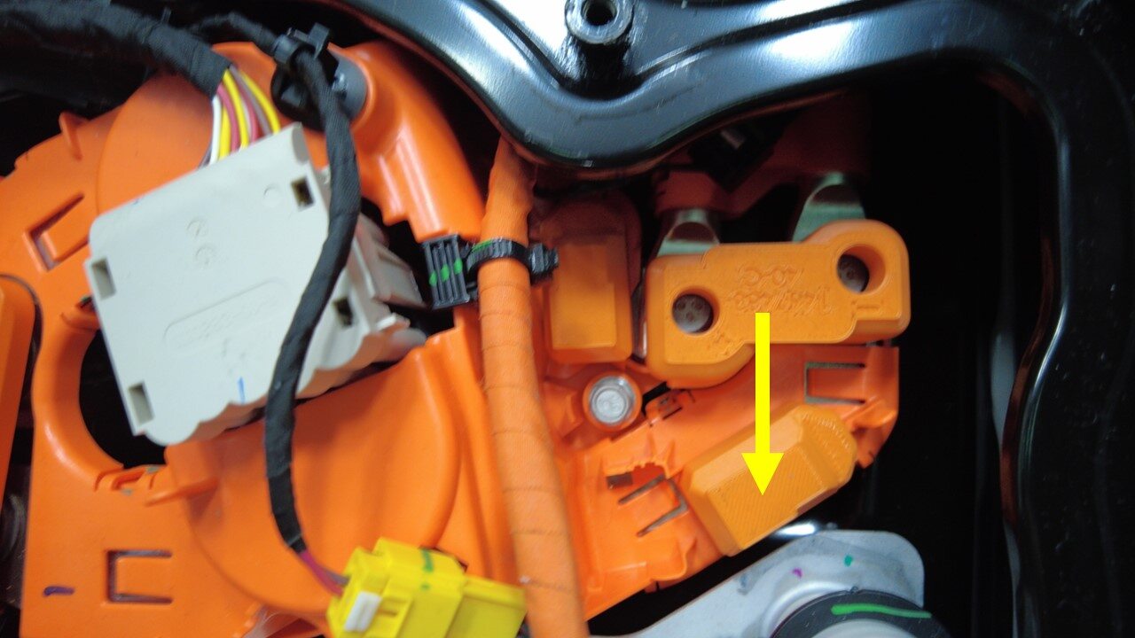
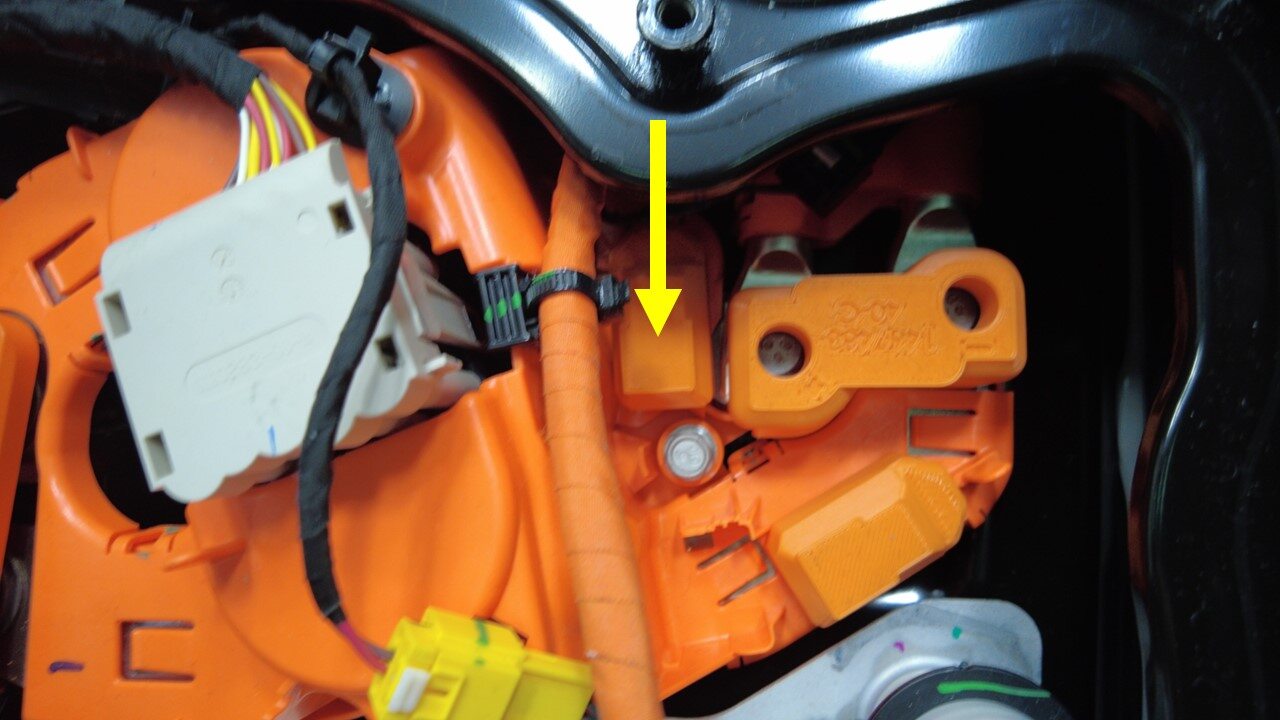
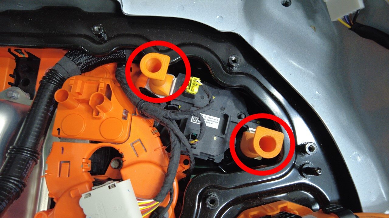
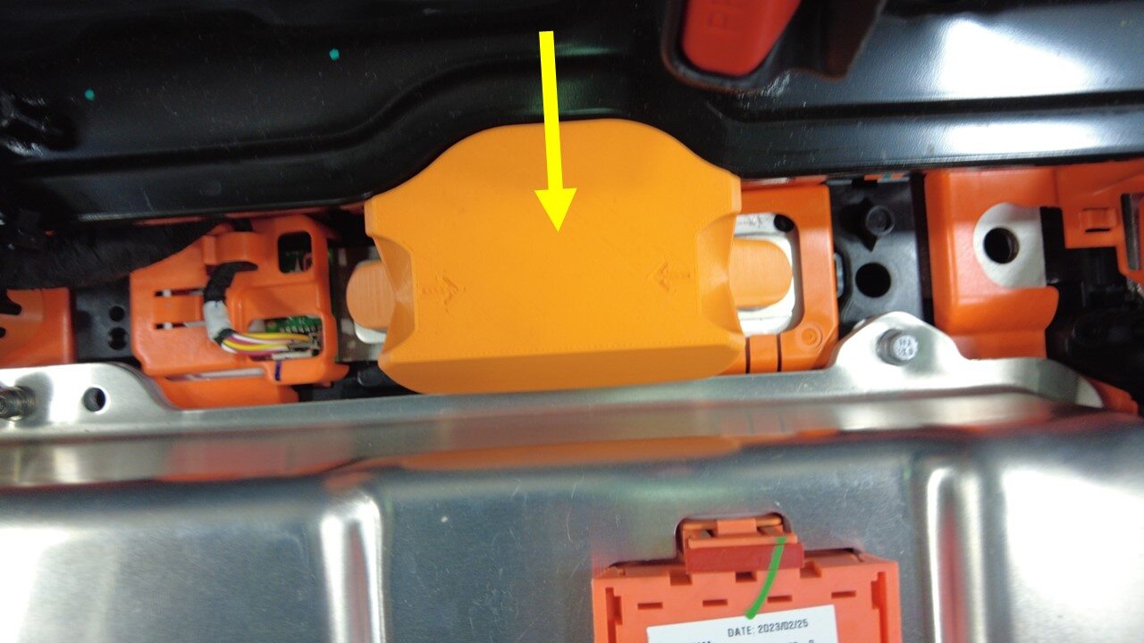
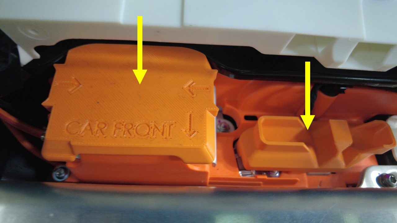
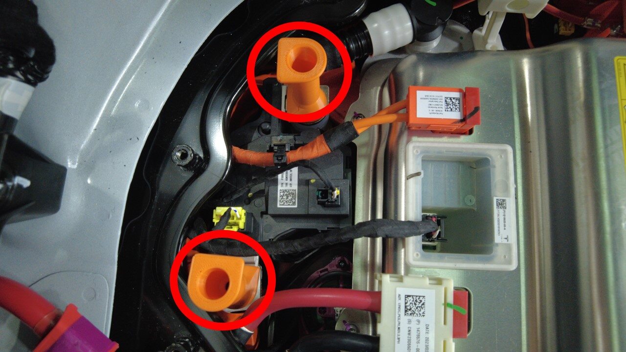
-
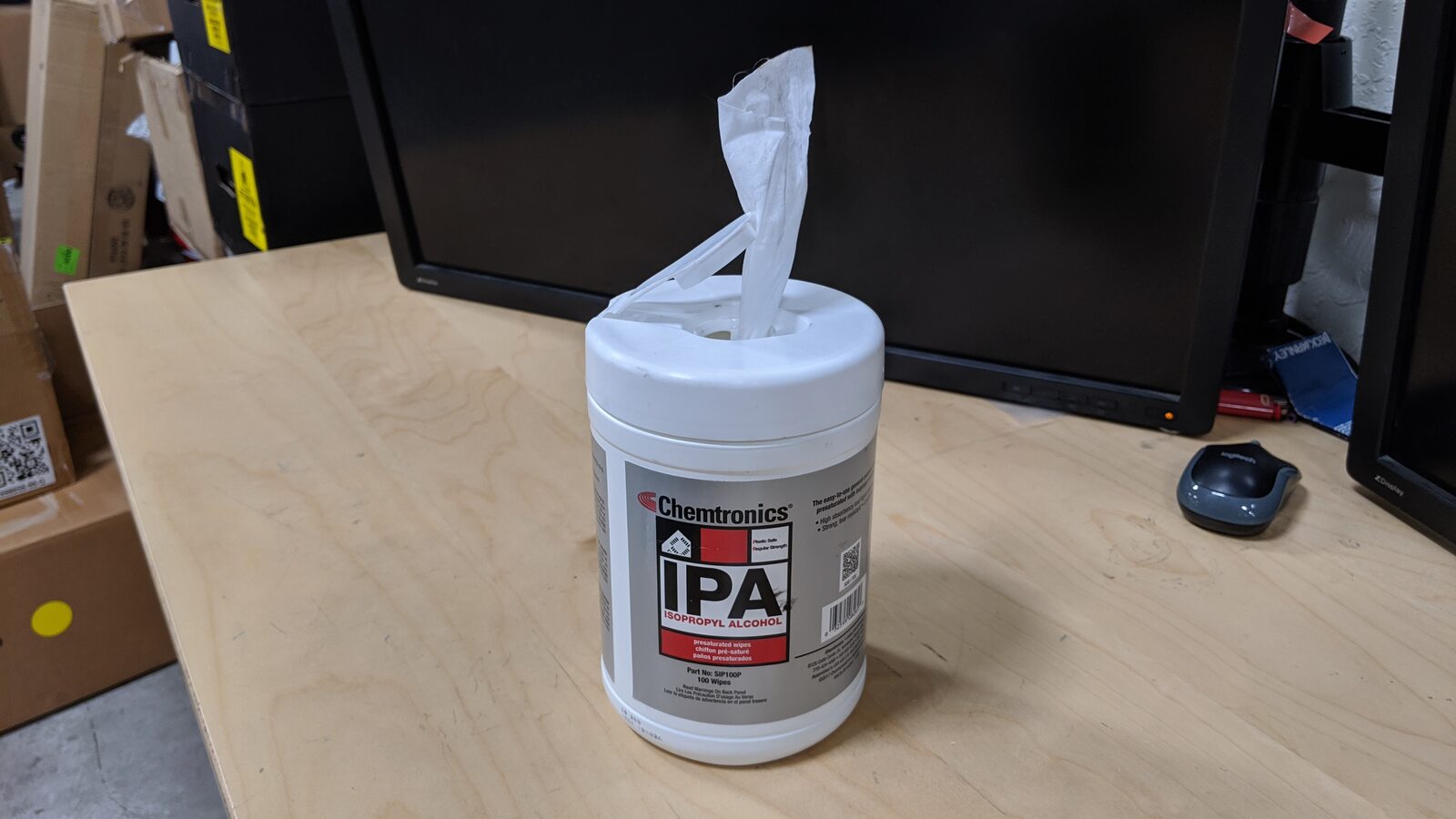
Wipe the ancillary bay with IPA to
clean surface
注Allow to 1 minute dry time
-
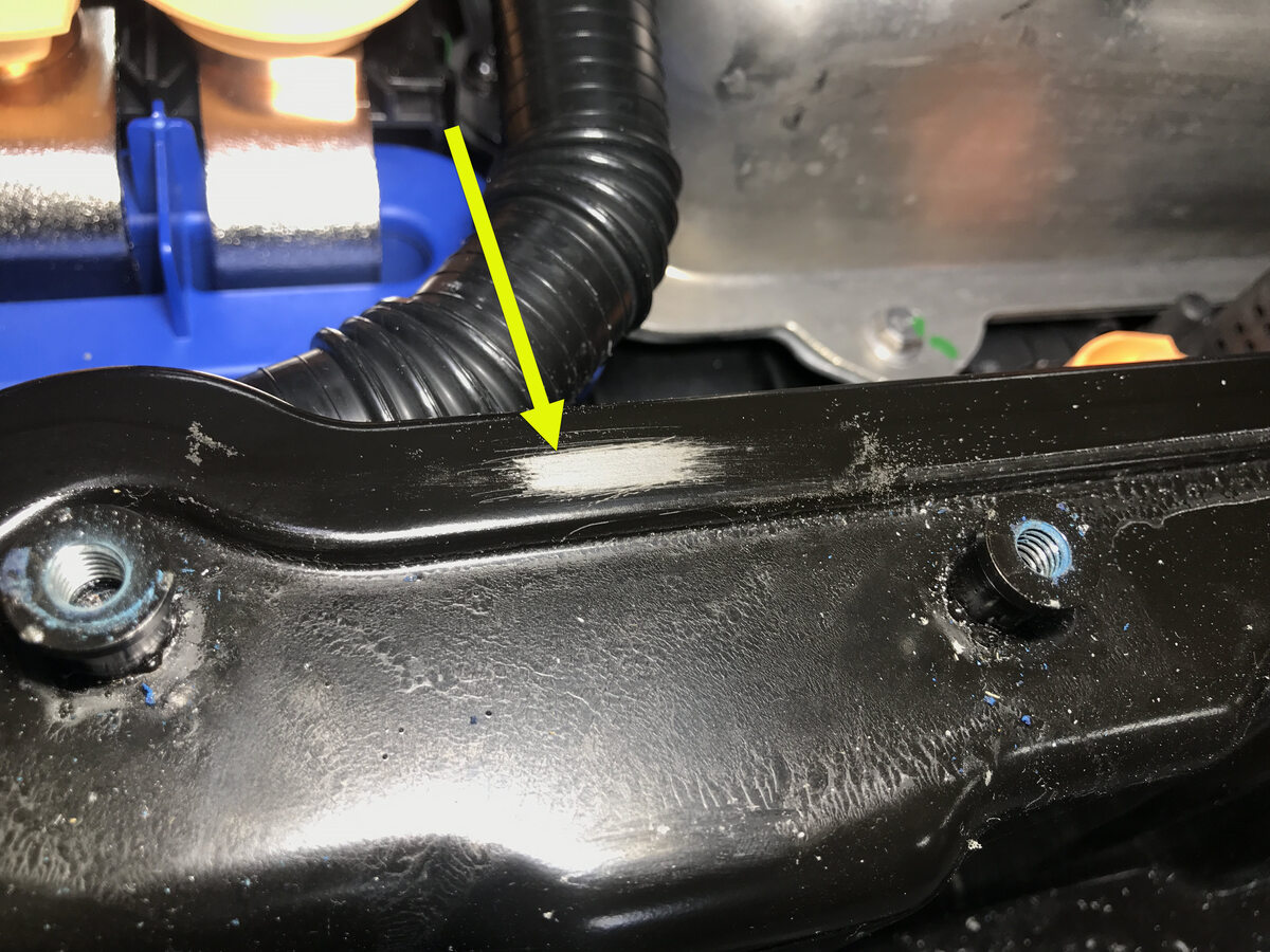
Inspect the ancillary bay walls for
damage
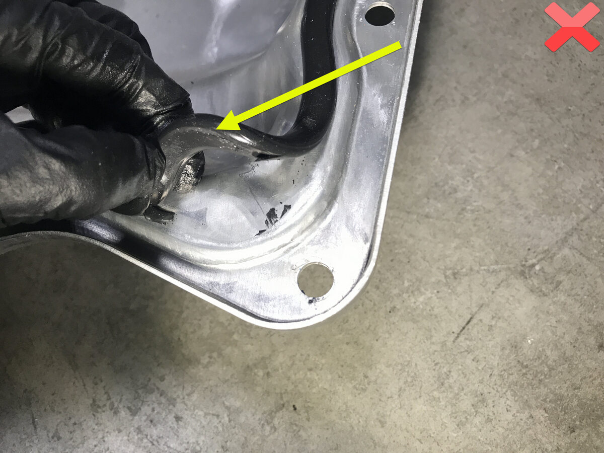
注Any dent or depression in the seal that causes it to not be flat will result in a leak, and cannot be reused, Any paint that comes off the ancillary bay wall, whether or not it sticks to the seal, will require enclosure leak test when reassembled, It can still be reused
-
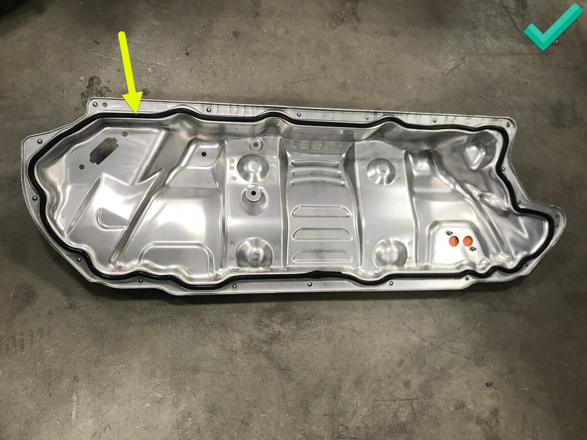
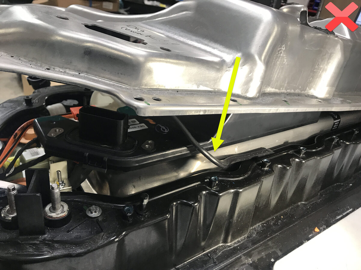
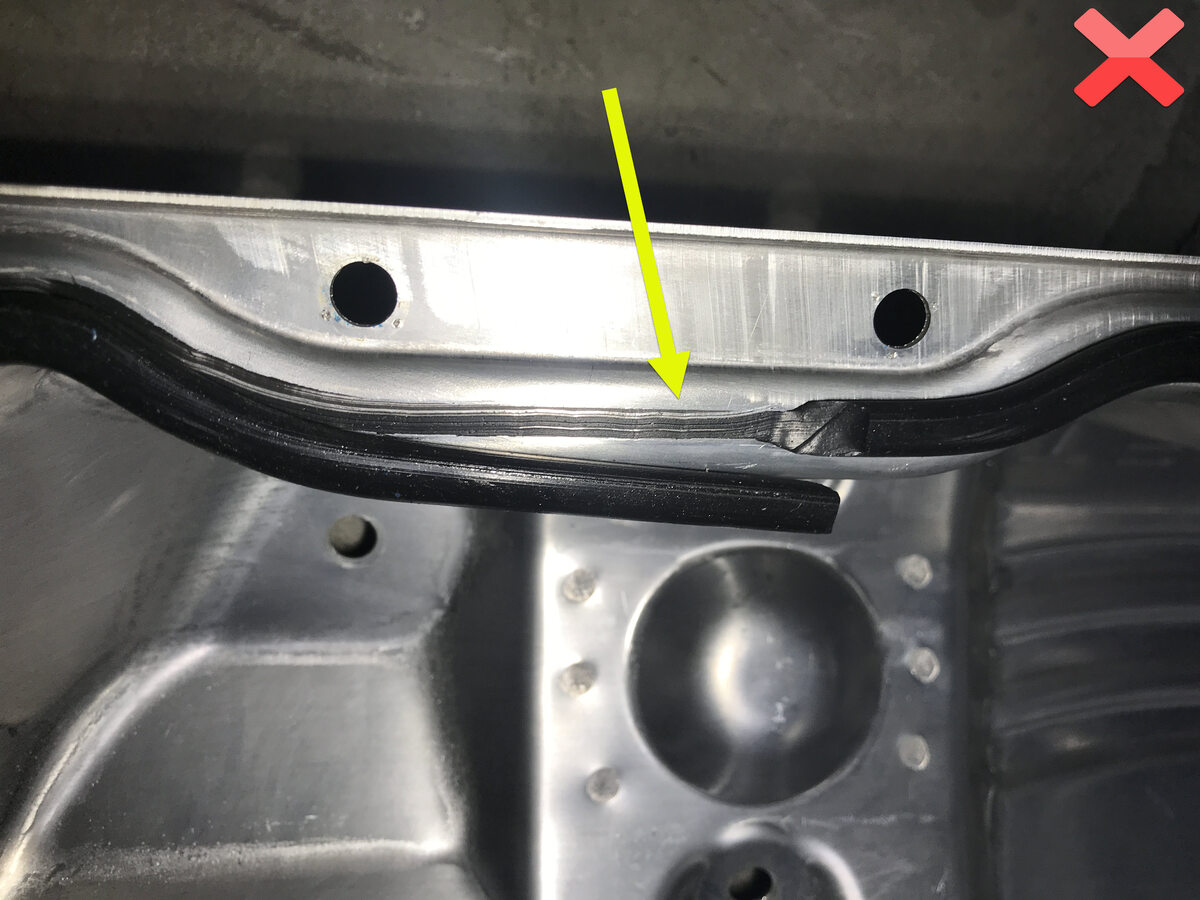
Inspect the ancillary bay cover seal
to confirm it has no visual damage
注Image up close for clarity, Delaminated and torn seals cannot be reused
-
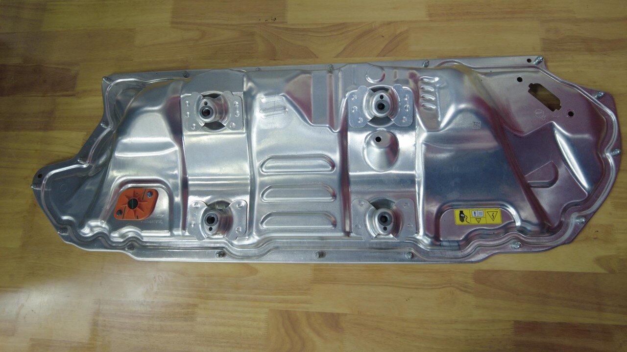
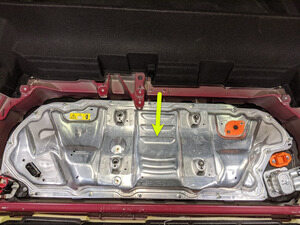
Position the ancillary bay cover to HV
battery for installation
注Ensure all accessible insulators are present, wearing Electrical Protective Gloves is not necessary once all HV components are covered.
-
Remove HV insulating gloves

-
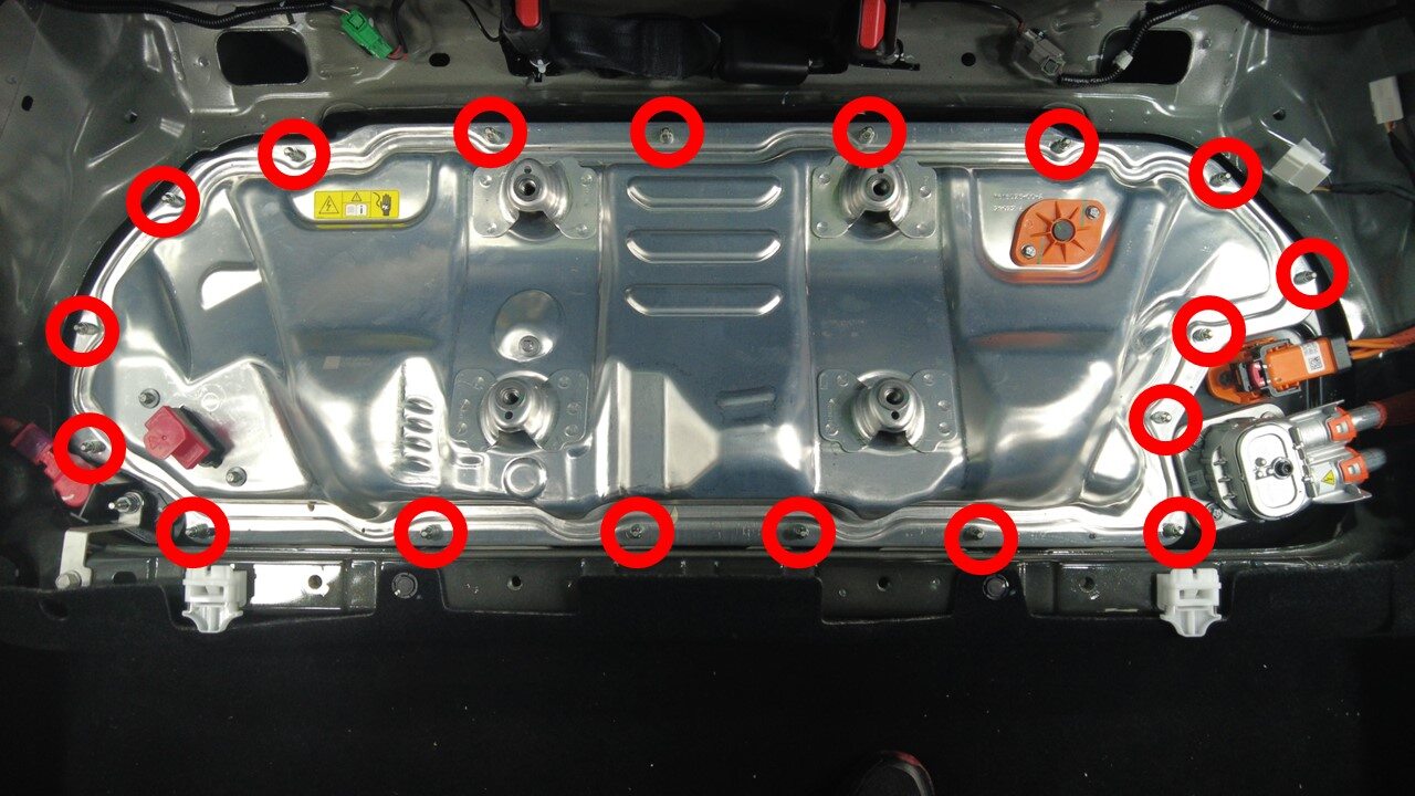
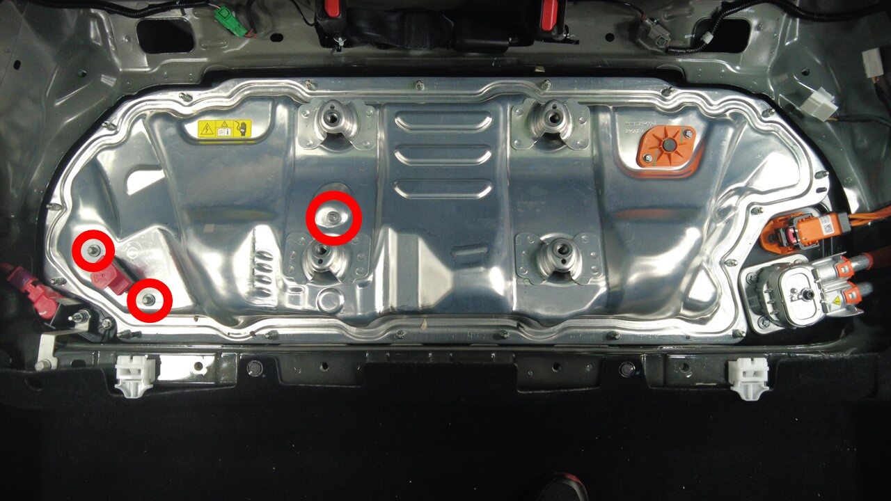
Install bolts securing the ancillary
bay cover to HV battery
注18x bolts, E10 5-Lobe, 8 Nm, Use E10 5-Lobe socket without magnet, Fasteners are captive, Follow torque sequence per image
-
Install bolts securing the ancillary
bay cover to HVC
注3x bolts, E10, 5 Nm + 30 degrees
-
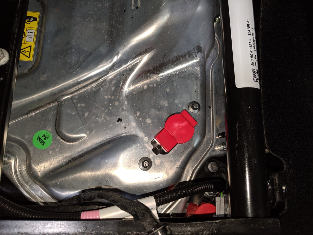
Remove logic cap and connect HVC logic
connector
注1x connector, 1x cap, Align connector then pull the handle to locking position get connector fully seated

-
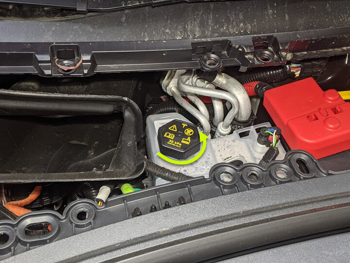
Remove coolant bottle cap
-
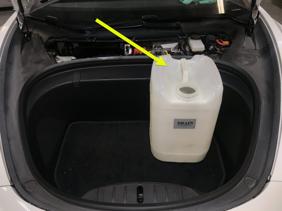
Place empty coolant container into
front storage area
-
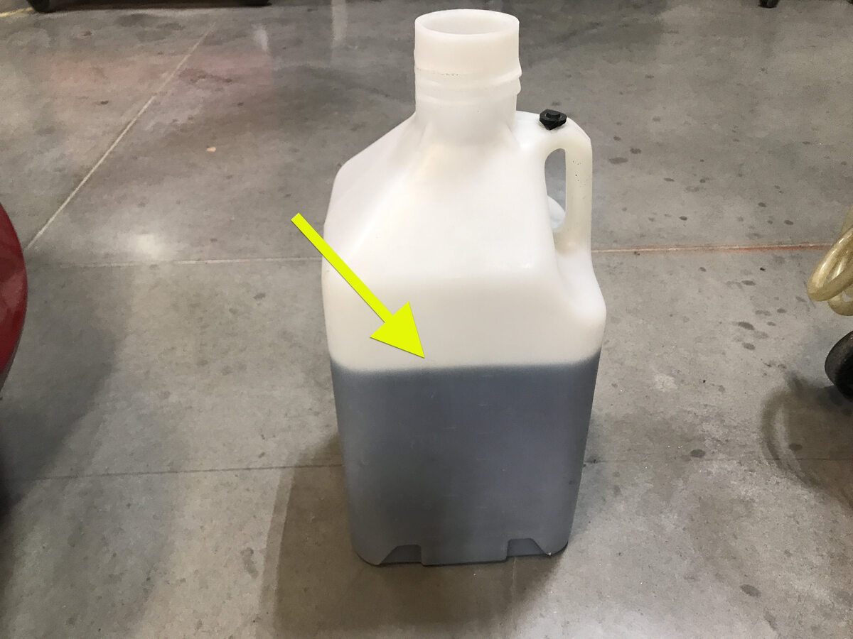
Fill container with at least 15L of
coolant
-
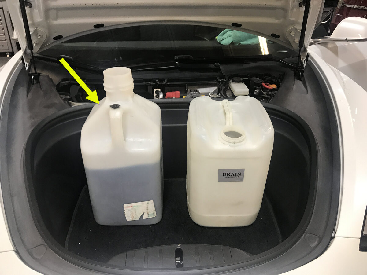
Place filled coolant container into
front storage area
-
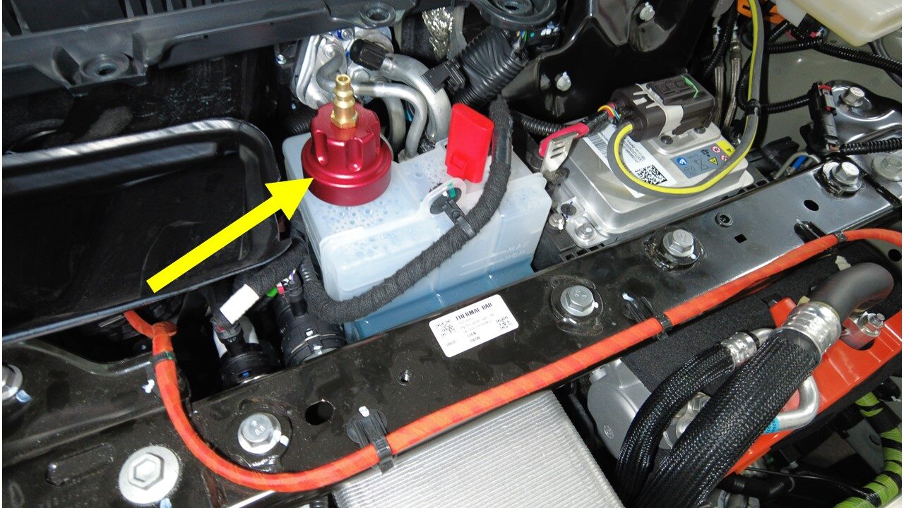
Install refill tool cap onto coolant
bottle assembly
-
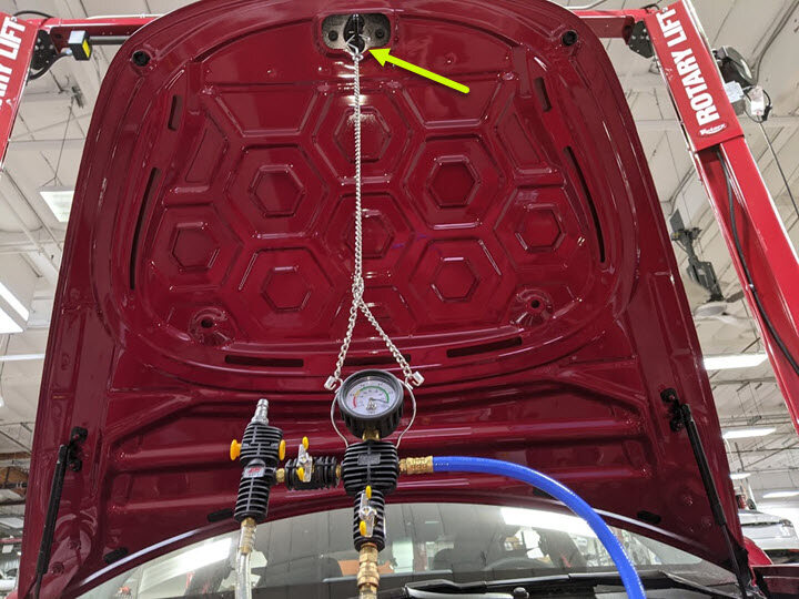
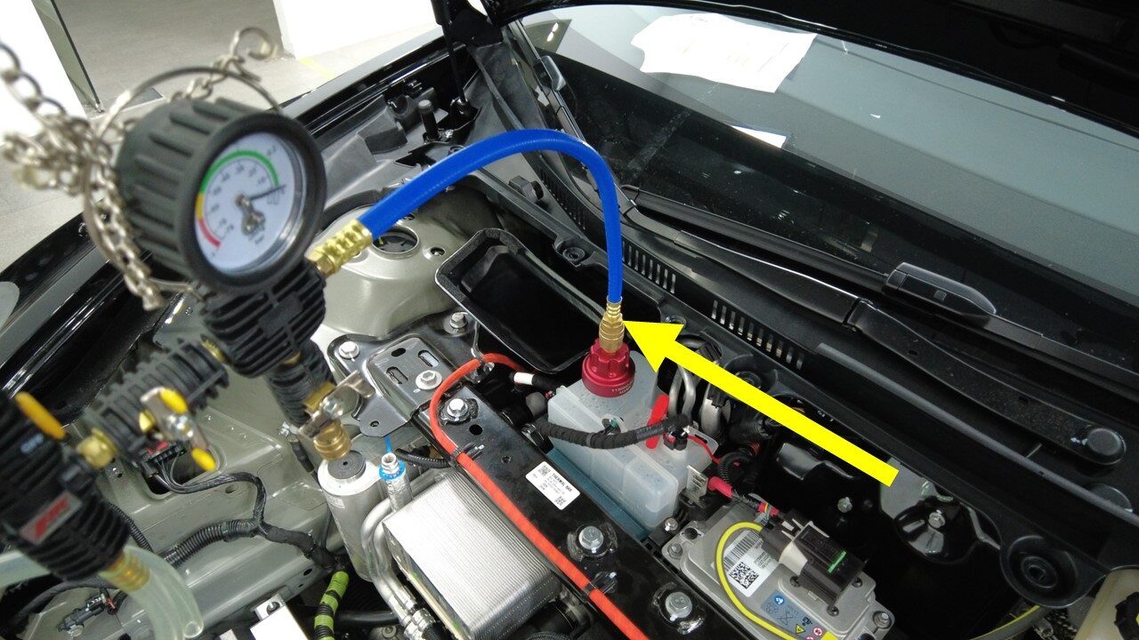
Setup vacuum refill tool
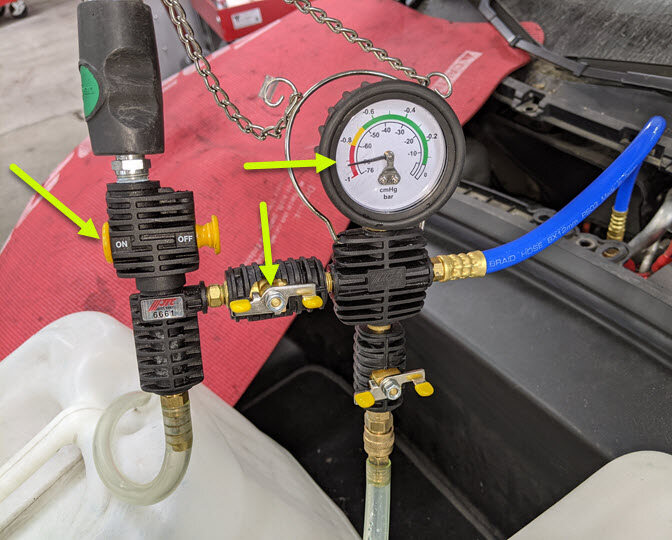
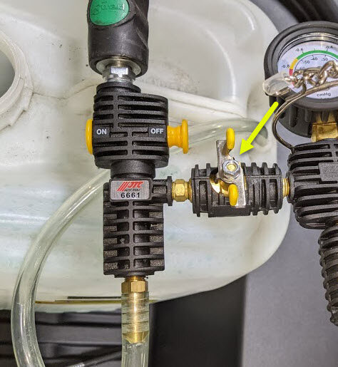
注Verify all valves on refill tool are in the closed position, See image for clarity

-
Install vacuum refill hose into refill
cap on coolant bottle
注Perform push-pull-push test to verify hose is fully engaged
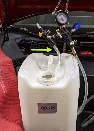
-
Position overflow hose into empty
container
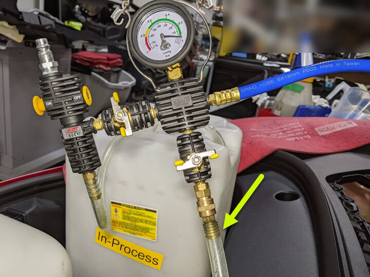
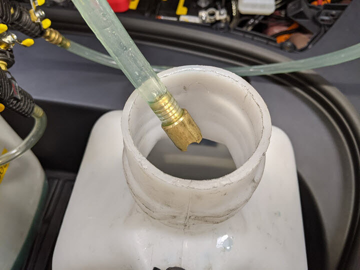
-
Place refill hose inside filled
coolant container
注Make sure hose end is fully submerged into coolant
-
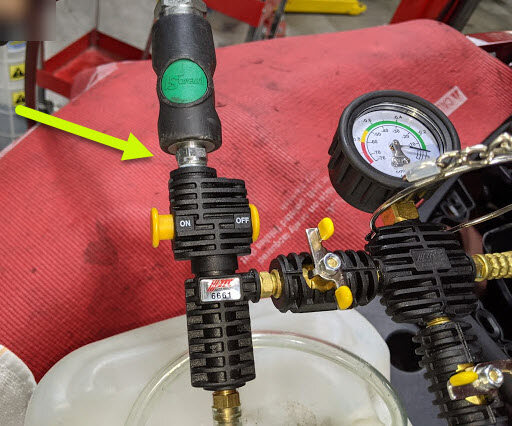
Connect shop air supply to coolant
refill tool
注If not already done, Verify refill valve is set to off
-
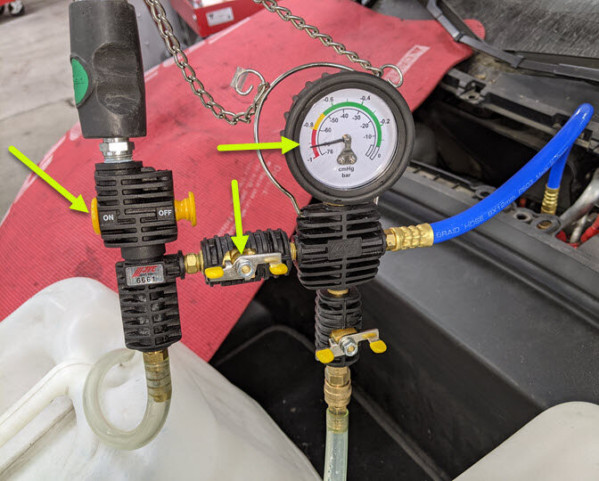
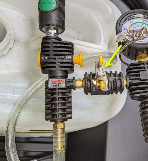
Open air inlet valve to draw a vacuum,
Once gauge stabilizes, Fully close valve
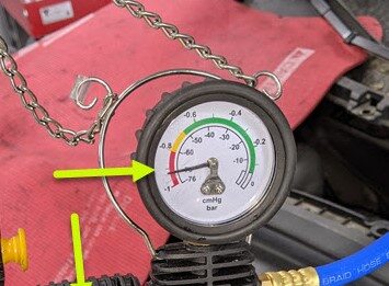
注Gauge stabilizes roughly (60-70 cmHg), Vacuum should not drop after the valves are closed
-
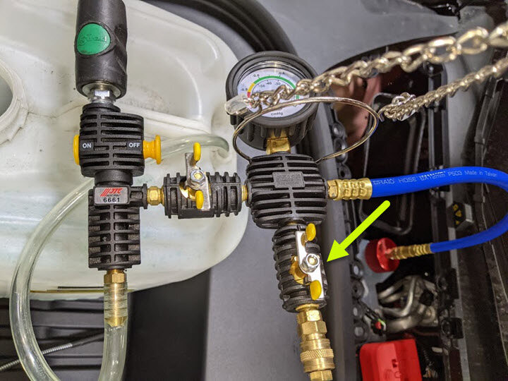
Slowly open coolant refill valve to
allow coolant to be drawn into coolant refill hose, Close valve when hose is full of
coolant
注This purges trapped air from the hose
-
Monitor gauge for 30 seconds to verify
a vacuum is maintained in cooling system
-
Reopen the air inlet valve for 3
minutes to continue evacuating cooling system, then close valve
-
Slowly open refill valve to allow
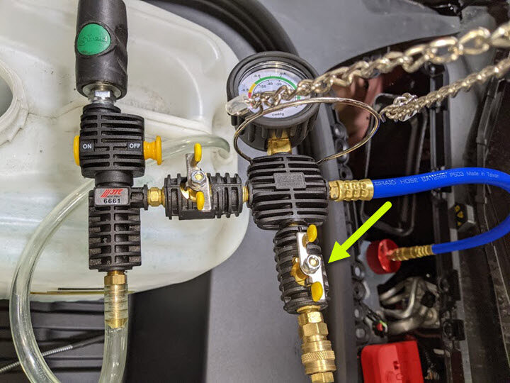
coolant to be drawn into system
注Make sure hose end of refill hose is fully submerged during entire process
-
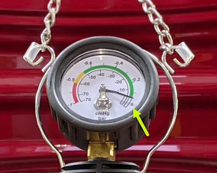
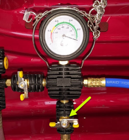
Once gauge reads zero, close refill
valve
-
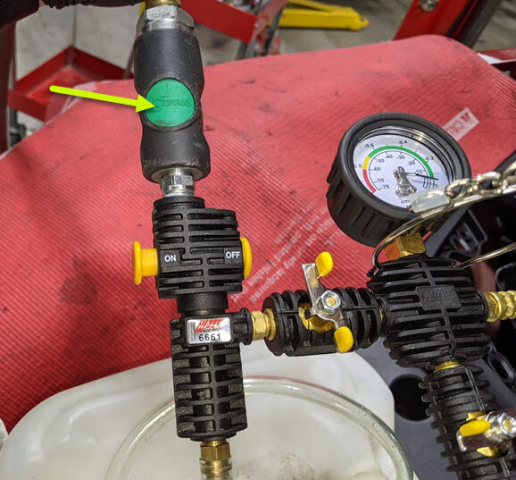
Disconnect shop air supply from
coolant refill tool
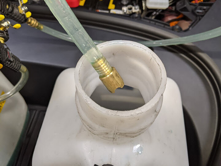
-
Remove coolant refill hose from
coolant container
-
Remove coolant overflow hose from
coolant container
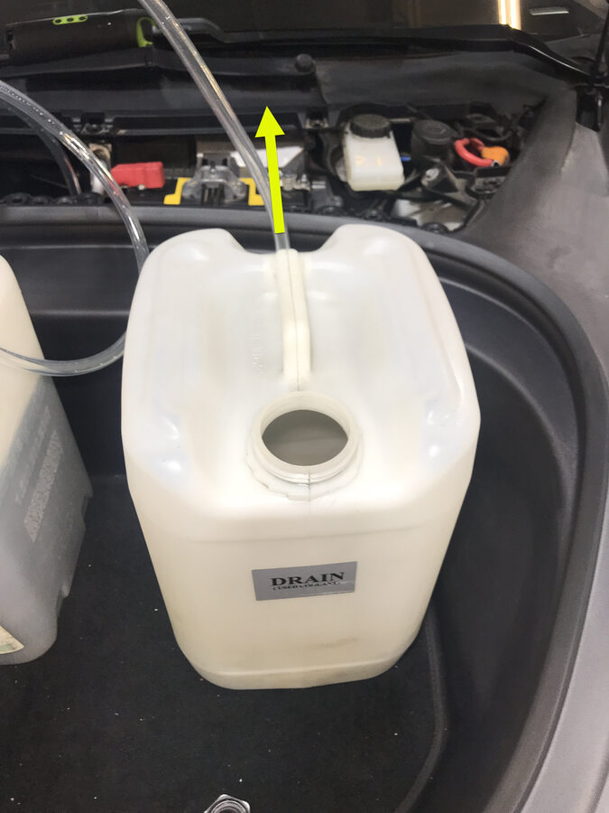
-
Remove vacuum refill hose from refill
cap on coolant bottle
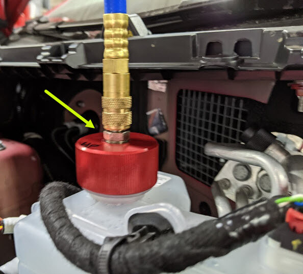
-
Remove coolant refill tool from
vehicle
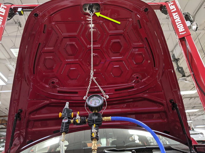
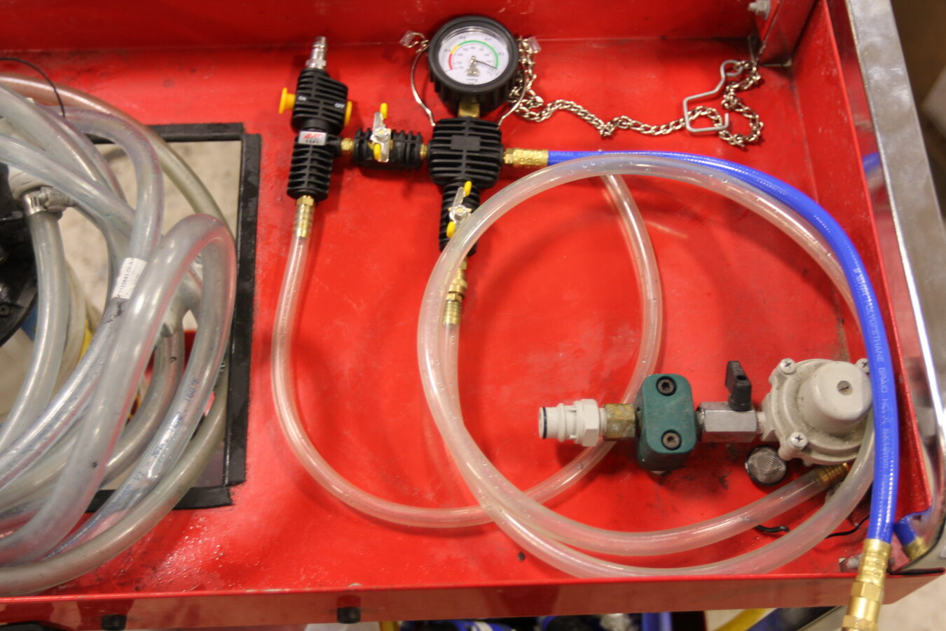
-
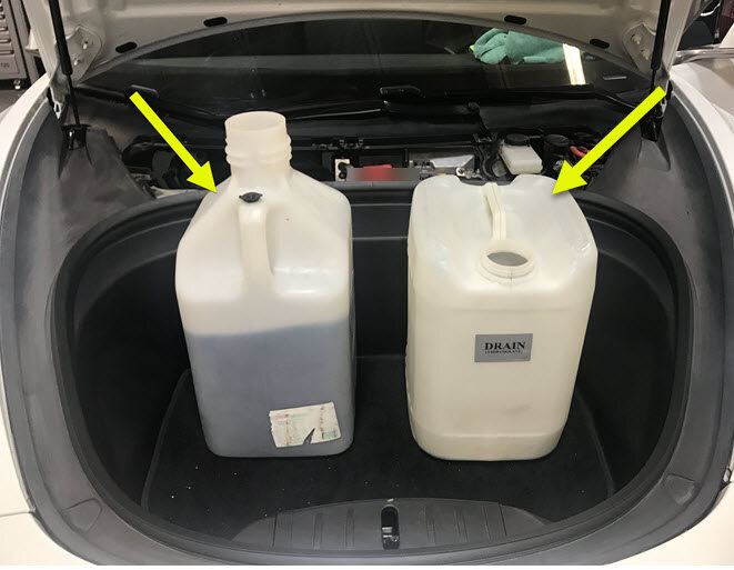
Remove both coolant containers from
inside underhood area
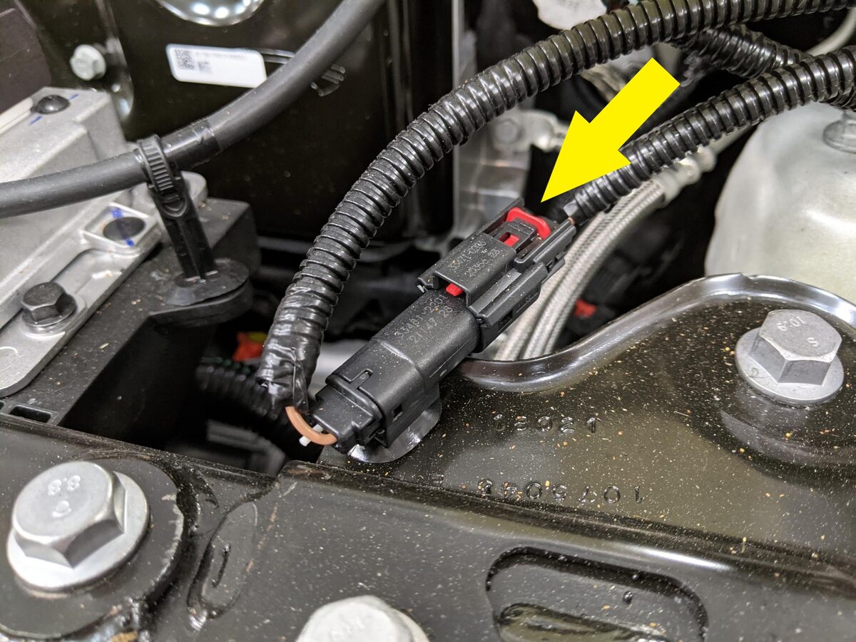
-
Connect first responder loop and leave
LV battery disconnected
注1x connector, Engage locking tab, Connect FRL but leave LV battery disconnected
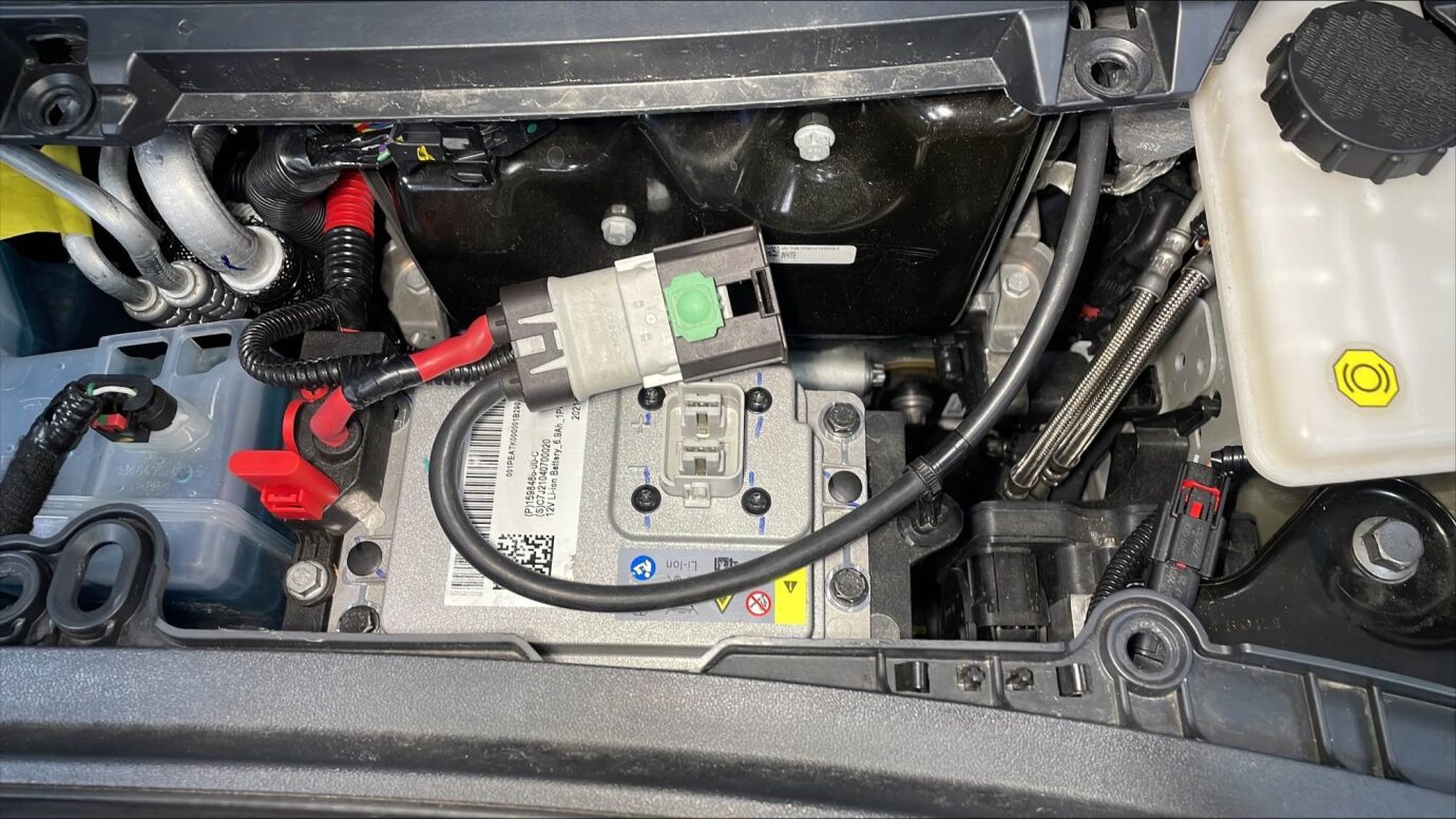
-
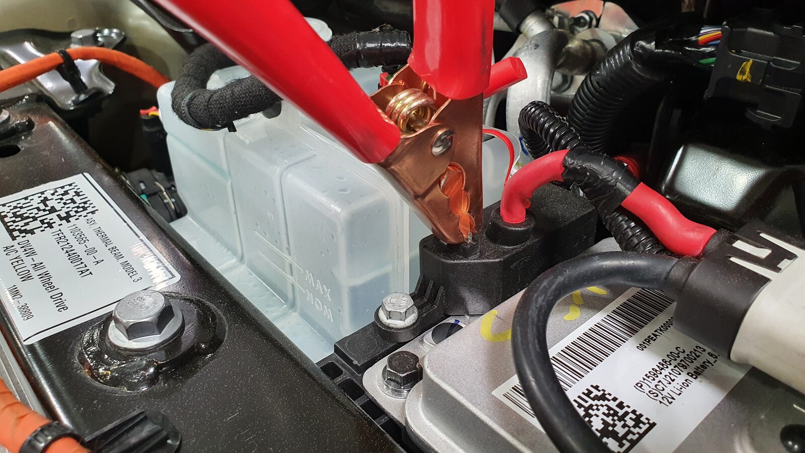
Connecting low-voltage battery
maintenancer-Charger
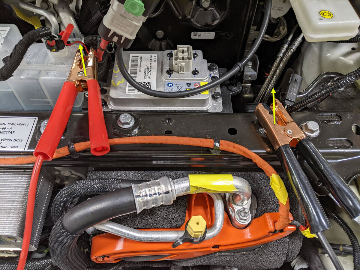
注Release positive terminal cover, Secure positive terminal to jump post, Secure negative terminal to bolt located between brake fluid reservoir and front trunk, Connect maintainer to power supply, To avoid damaging the vehicle DO NOT allow positive cable to make contact with other metal components, Never have a float charger and the LV battery simultaneously connected for any extended period of time
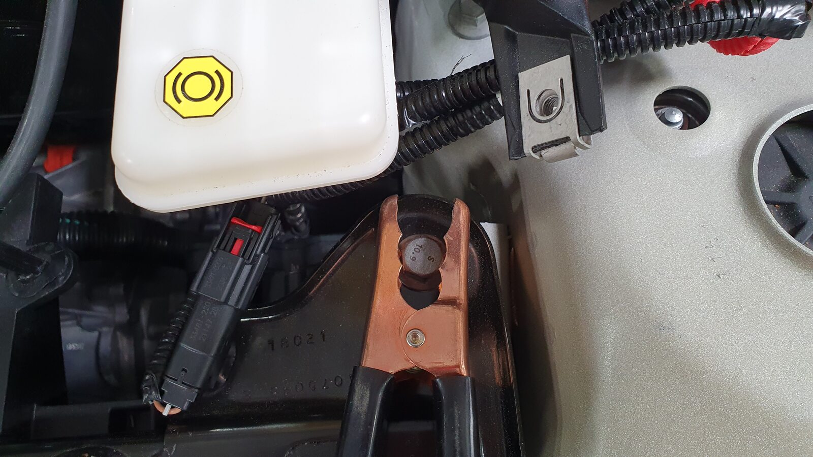
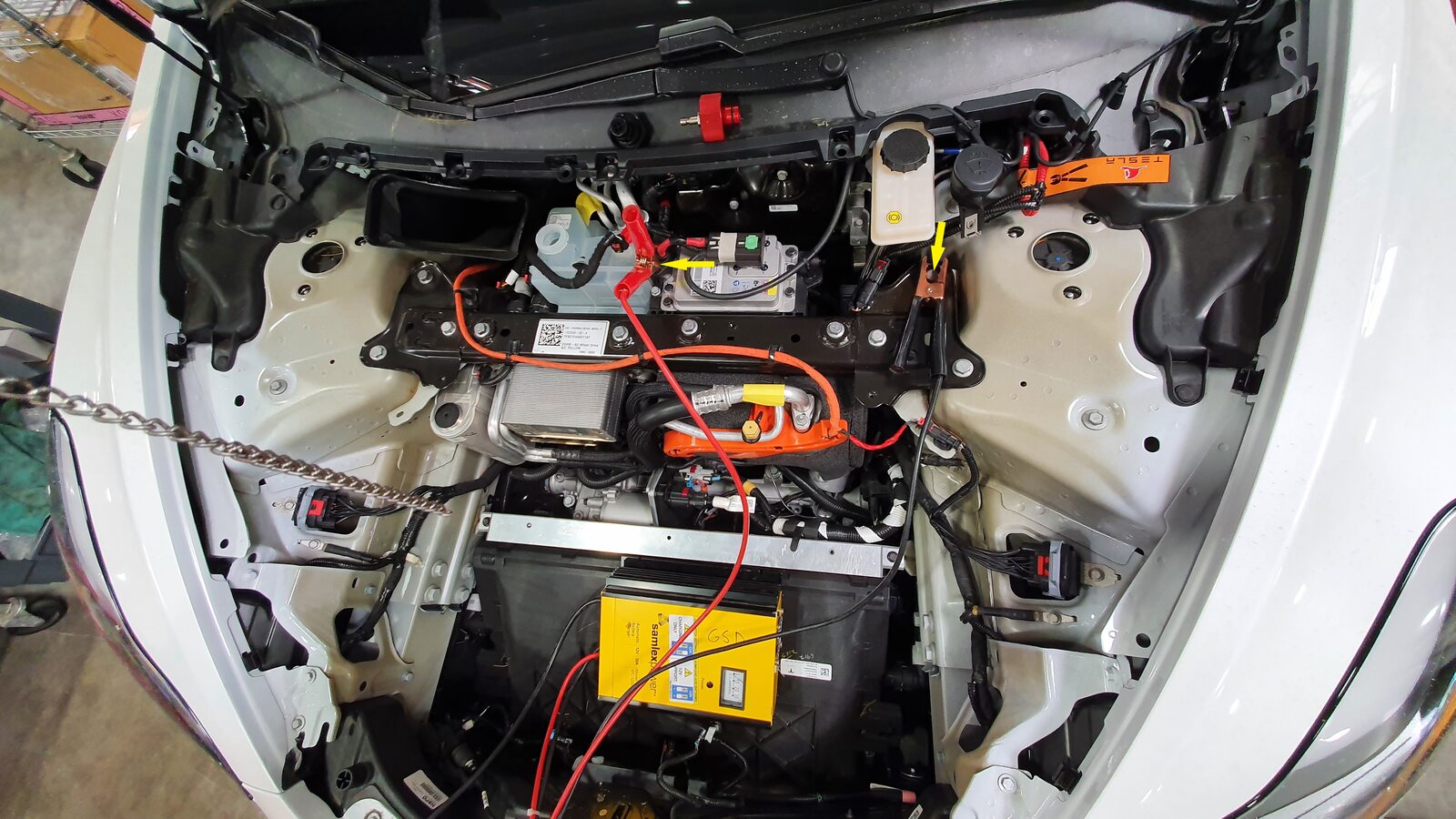
-
Select "Stop Thermal Fill Drain"
through UI
注Allow routine to complete, ensure routine is successful
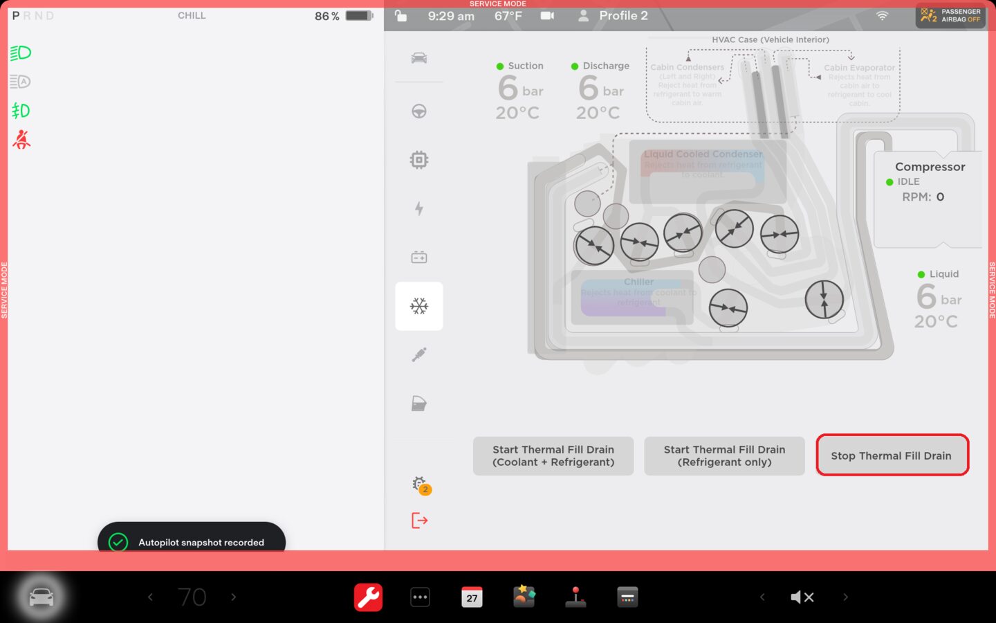
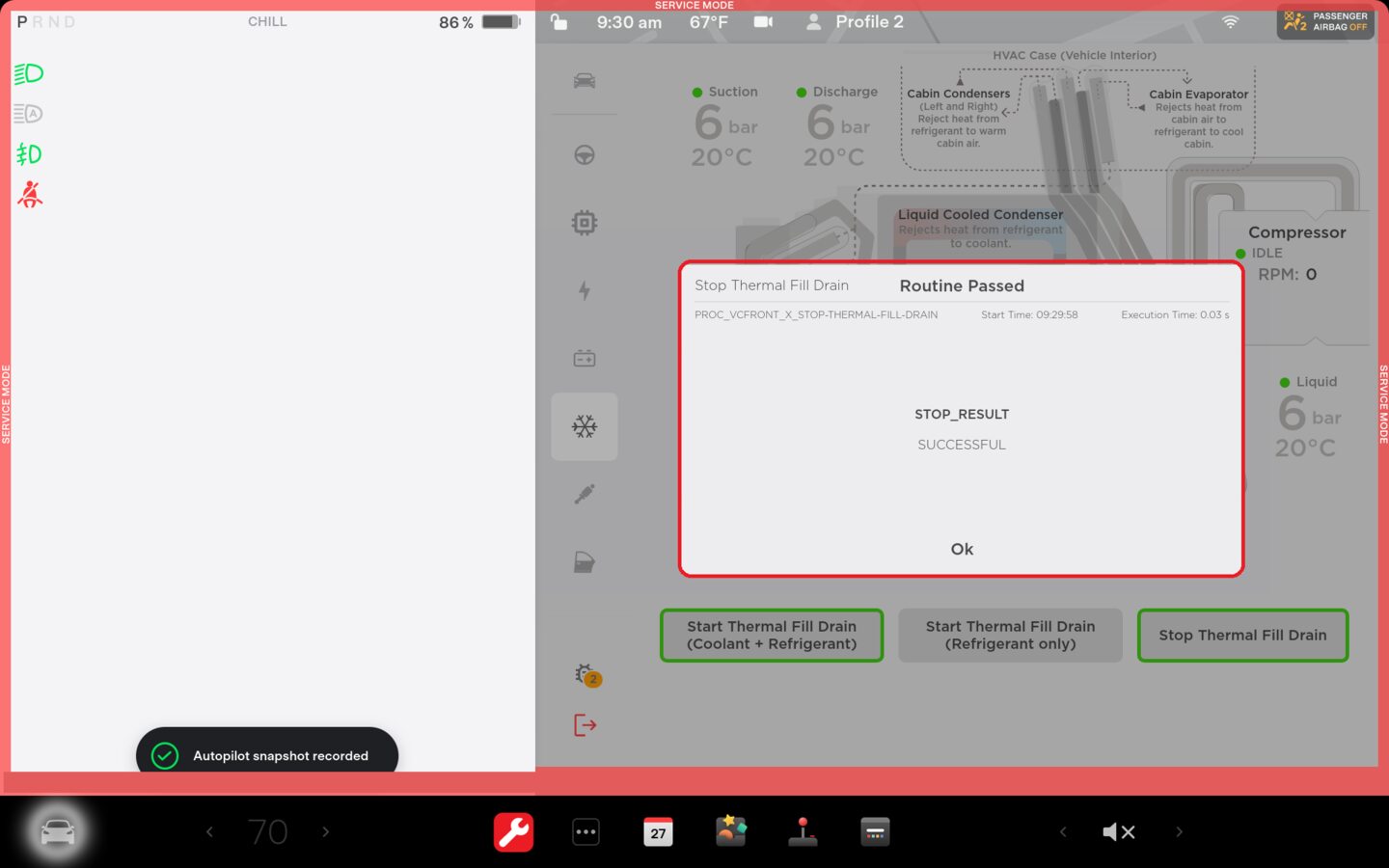
-
Reinstall Firmware via service
UI
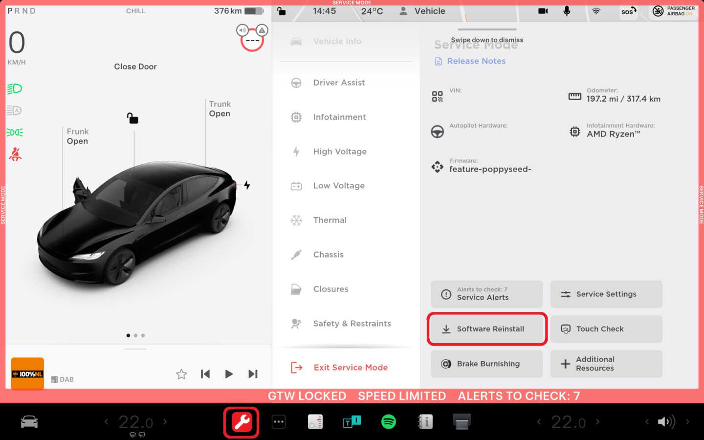
注Controls > Service Mode > Software Reinstall, Installation will begin immediately

-
Disconnect low-voltage battery
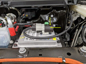
maintenancer-Charger and connect LV battery
-
Inspect coolant level and top off as
necessary
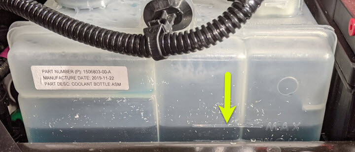
注Ensure that fluid level is at Max line
-
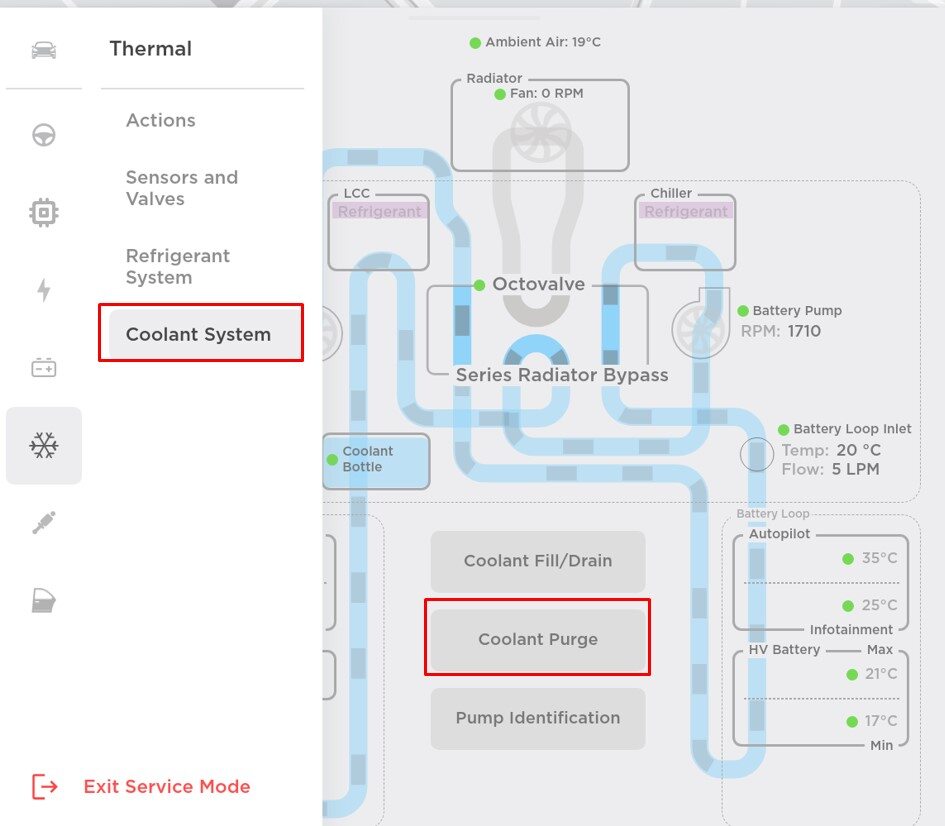
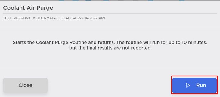
Select "Start Coolant Air Purge" using
the UI
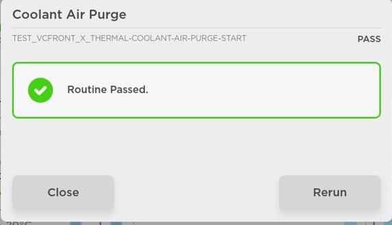
注Wait until coolant pumps stop running (audible noise), Routine Passed will appear, but pumps will run for 10 minutes, If you start next another routine during this time, it will fail, Make sure vehicle is not in "Drive", Routine is still running despite the completed message, Speeds can be monitored in garage under PT Thermal tab, Idle speed = ~1500 RPM, Test will vary speeds from 3500-6500 RPM and actuate valves between SERIES and PARALLEL, Putting vehicle into "Drive" will stop this routine, If speeds hover at 7000 RPM, this indicates the pumps are air locked, perform a vacuum fill, Continue to add coolant and purge until the coolant level reaches between the NOM and MAX Lines on the bottle
-
Inspect coolant level and top off as
necessary
注Ensure that fluid level is at Max line
-
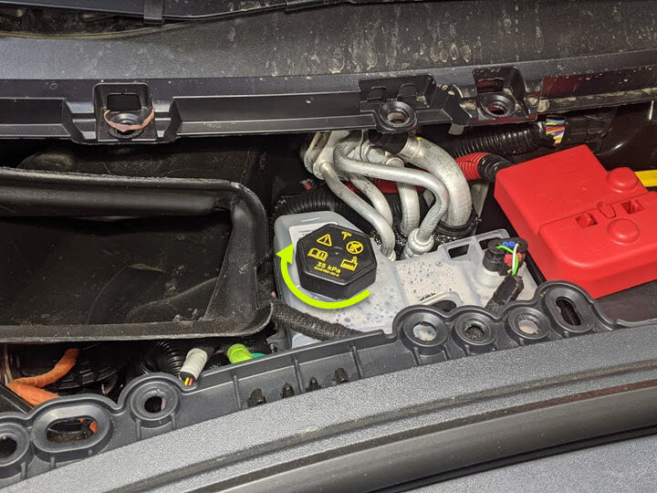
Install coolant bottle cap
-
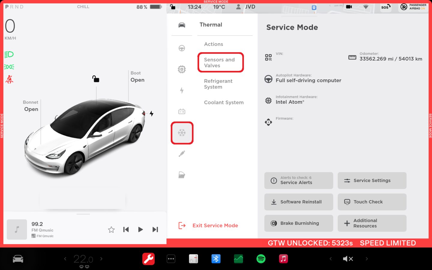
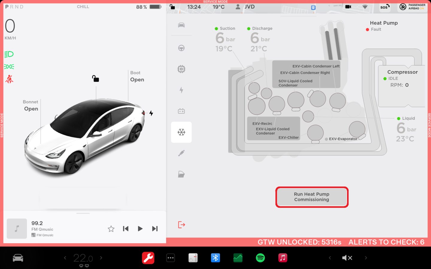
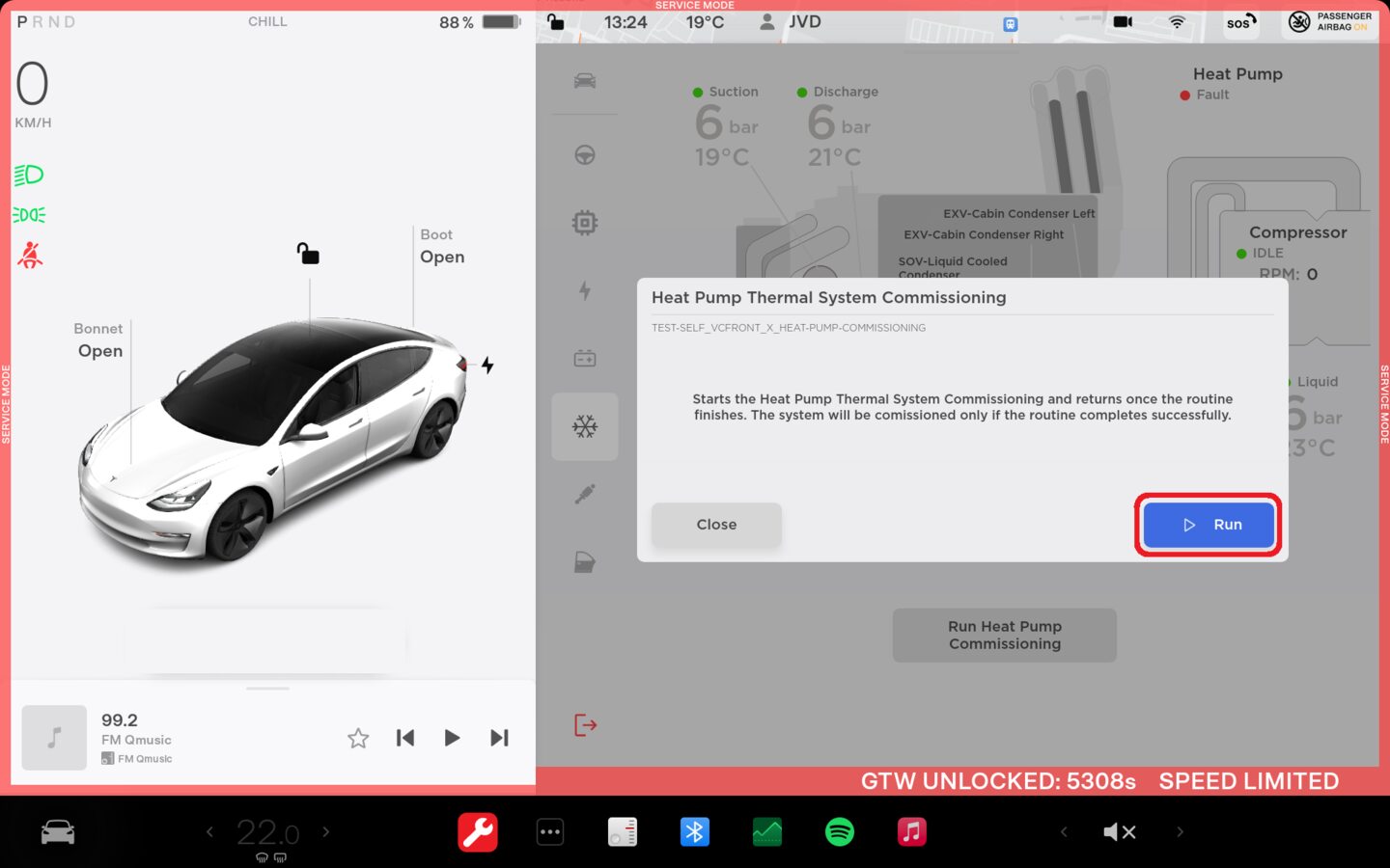
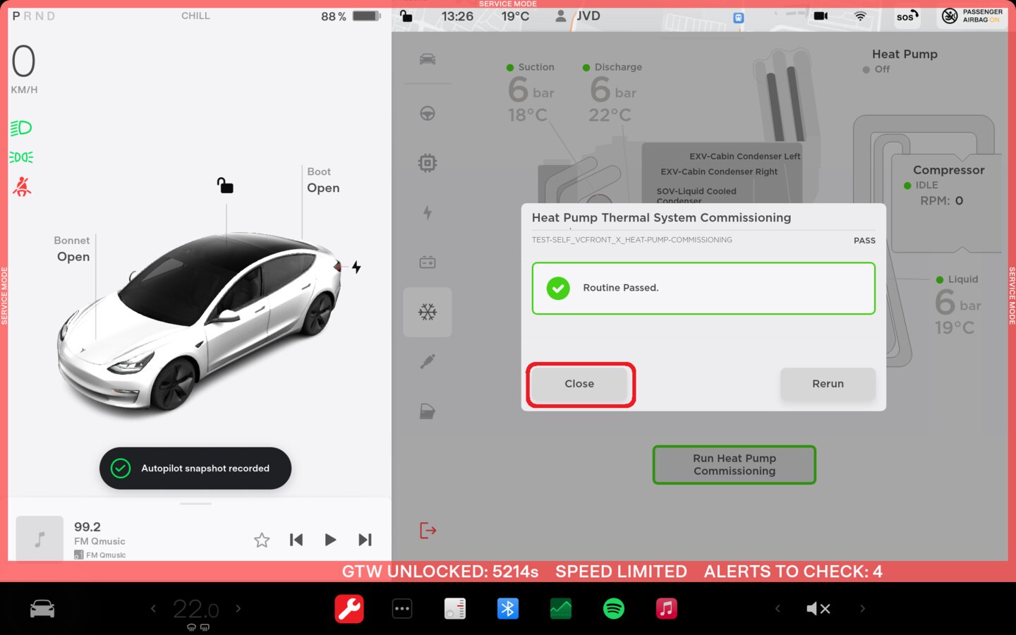
Perform Heat Pump Commissioning
through UI
注Select Thermal > Sensors and Valves > Run Heat Pump Commissioning, click Run, close once routine is passed
-
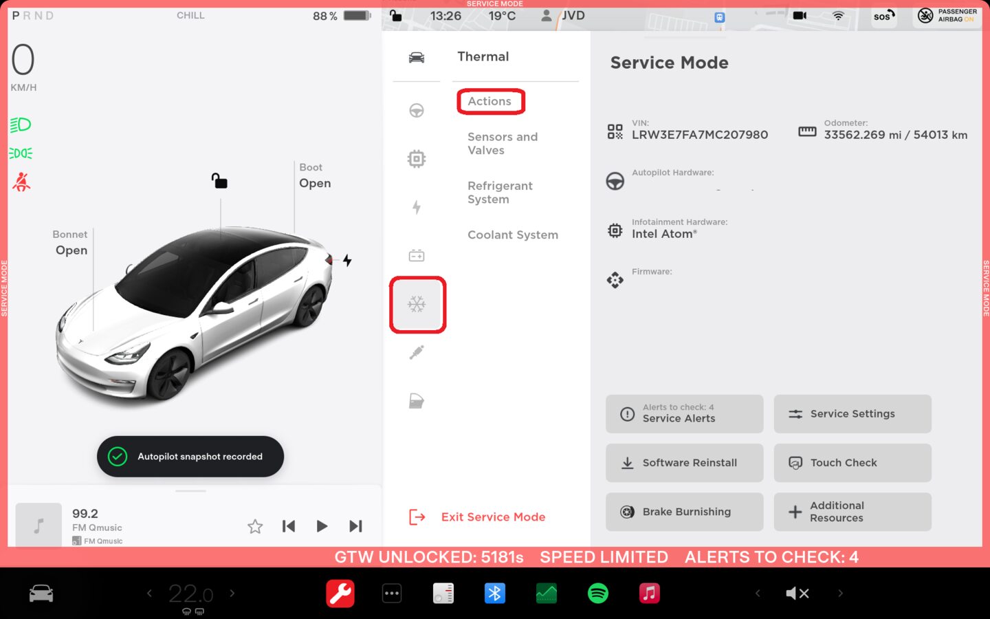
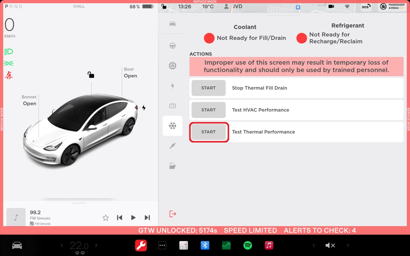
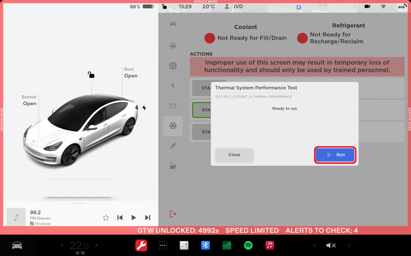
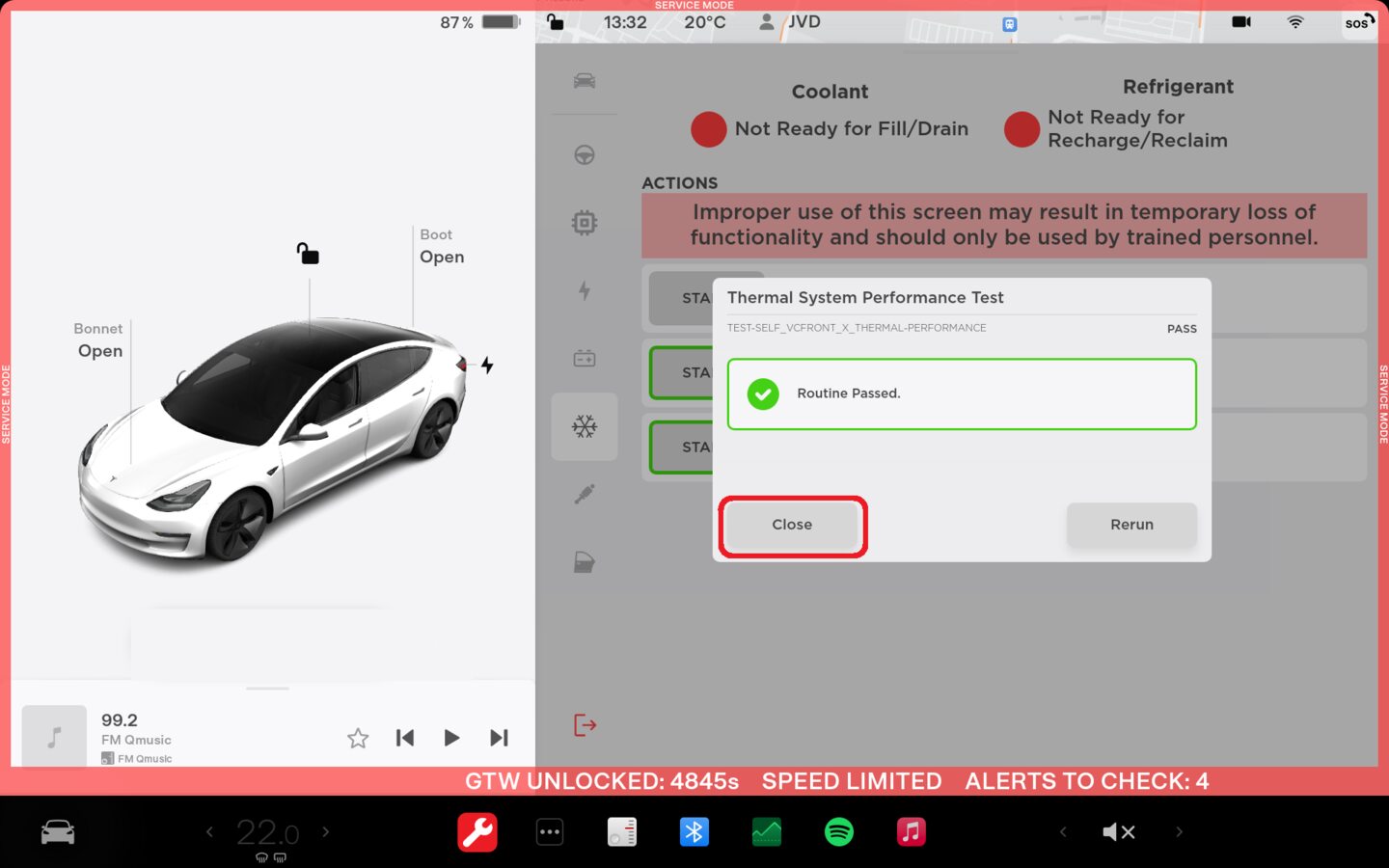
Perform Thermal Performance through
the UI
注Select Thermal > Actions > Test Thermal Performance, click Run, close once routine is completed, if thermal test fails follow https://toolbox.teslamotors.com/articles/206000
-
Connect 2nd row seat harness and
secure cushion
注2x clips, 2x connectors, Insert buckles through holes, Slide rear inward then align front clips, Perform push-pull-push test
-
Install rear underhood apron
注14x clips, Hold rear wall of frunk to keep from flexing while engaging front clips
-
Close hood
-
Move RH front seat to original
position
-
Move LH front seat to original
position
-
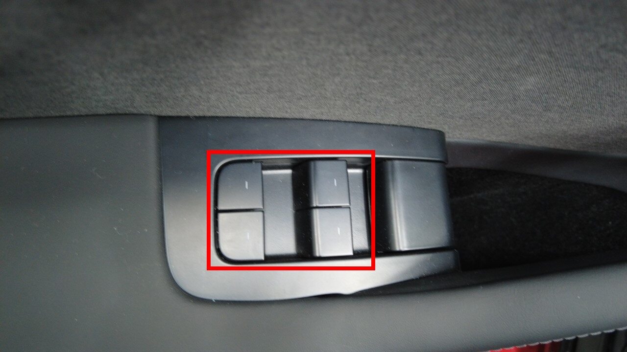
Raise all windows
-
Close all four doors