02/01/2024 18:53:48
油底壳密封件 - HVAC 总成(拆卸和更换) ((拆卸和更换))
 校正代码
18101302 4.68
注意:除非本程序中另有明确规定,否则上述校正代码和 FRT 反映的是执行本程序(包括关联程序)所需的所有工作。除非明确要求,否则请勿堆叠校正代码。
注意:请参阅平均维修工时,深入了解 FRT 及其创建方式。要提供有关 FRT 值的反馈,请发送电子邮件至LaborTimeFeedback@tesla.com。
注意:执行下述程序时,请参阅人员保护确认已穿戴适当的个人防护装备 (PPE)。
校正代码
18101302 4.68
注意:除非本程序中另有明确规定,否则上述校正代码和 FRT 反映的是执行本程序(包括关联程序)所需的所有工作。除非明确要求,否则请勿堆叠校正代码。
注意:请参阅平均维修工时,深入了解 FRT 及其创建方式。要提供有关 FRT 值的反馈,请发送电子邮件至LaborTimeFeedback@tesla.com。
注意:执行下述程序时,请参阅人员保护确认已穿戴适当的个人防护装备 (PPE)。
警告
尽管此程序已经过验证,但仍是一个草案。可能没有警告和注意事项。请遵守安全要求,处理或靠近高压系统和部件时,请谨慎操作。请将校正修理内容及反馈发送至ServiceDevelopment@teslamotors.com。
-
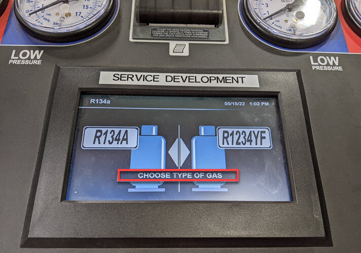
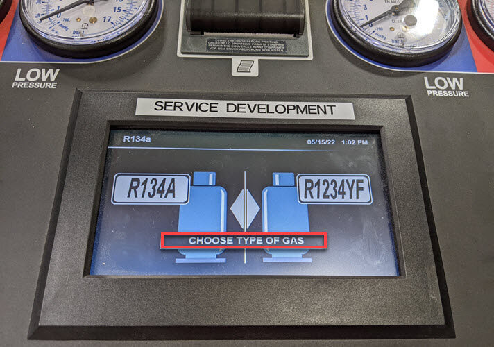
Set up AC machine
注Touch time only, Connect to power, Turn power switch on, and select gas type
-
Open all four doors
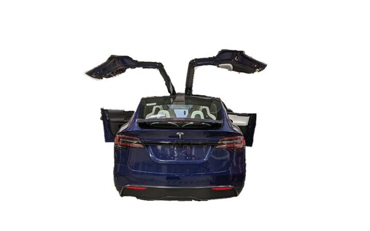
- Lower both front windows.
-
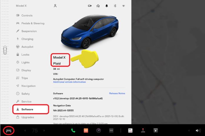
Activate Service Mode using the touchscreen.
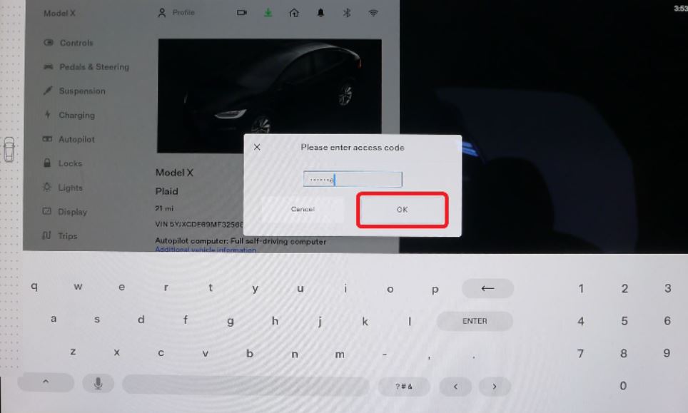
-
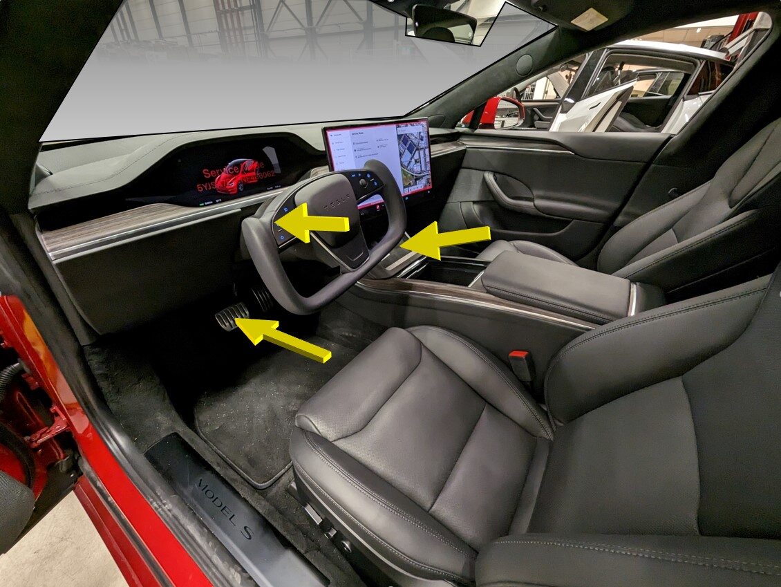
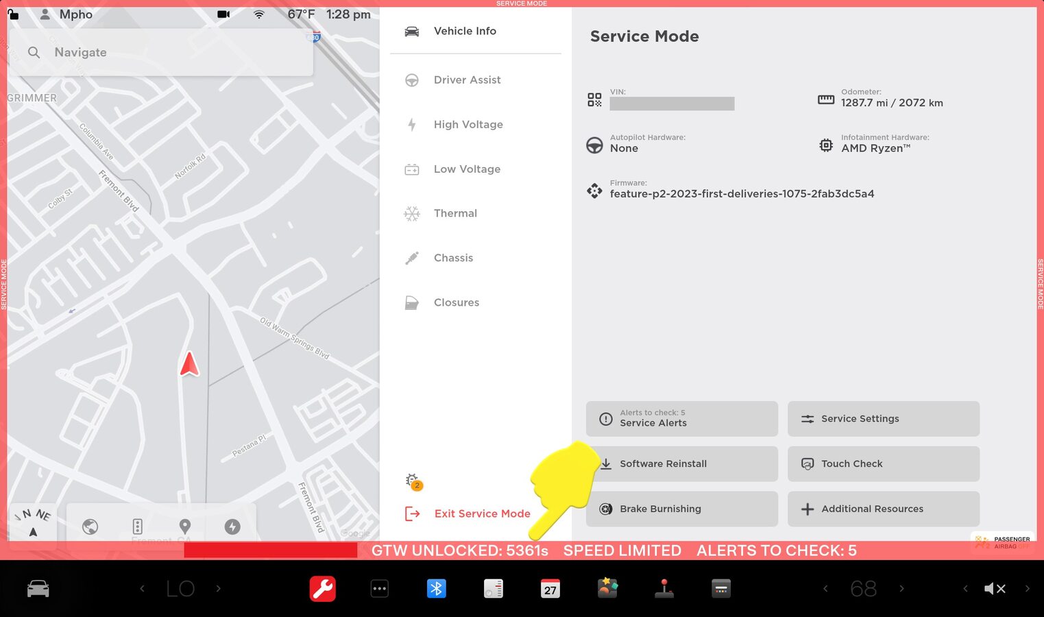
Unlock Gateway
注After vehicle has been put into "Service Mode", place keycard on center console to turn on drive rails, hold down the brake pedal, while keep pressing right hand signal button simultaneously for at least 10 seconds, "GTW UNLOCKING" should pop up on the UI right next to the VIN during these 10 seconds, once gateway is unlocked "GTW UNLOCKED 5400" will be displayed on the UI next to the VIN, the gateway will remain unlocked for 90 minutes, follow steps on Toolbox article #5582900 for any additional information
-
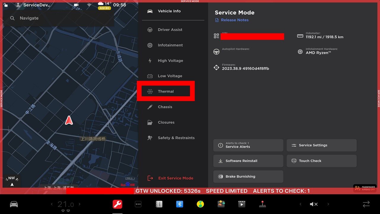
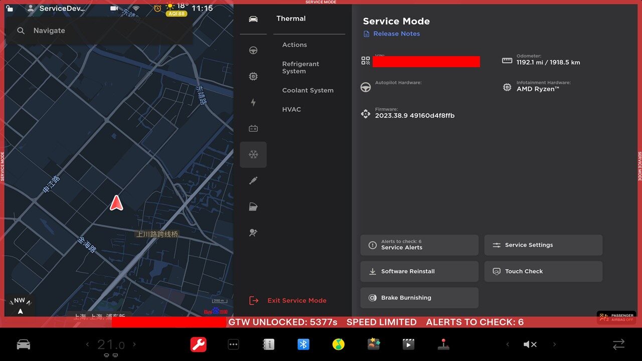
Access Thermal System routines using the UI
注Select Service mode > Thermal
-
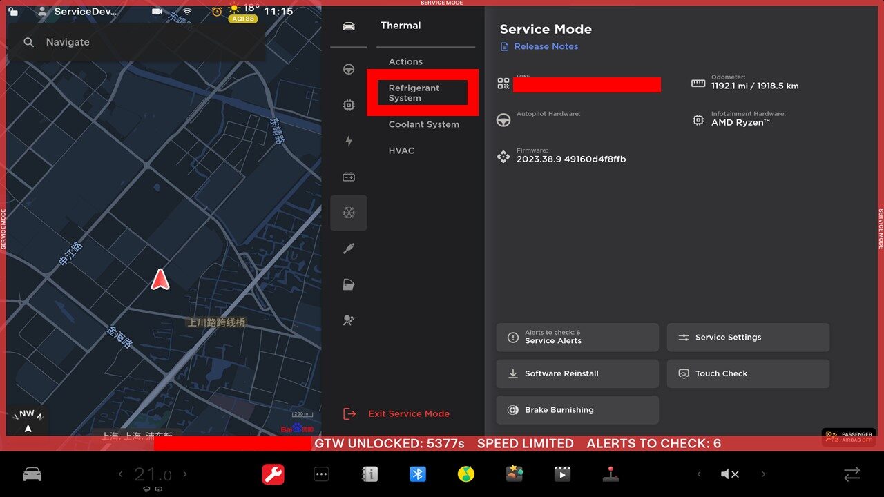
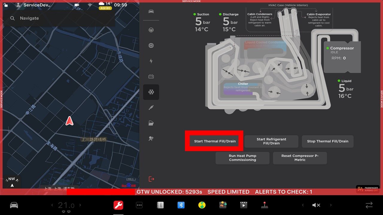
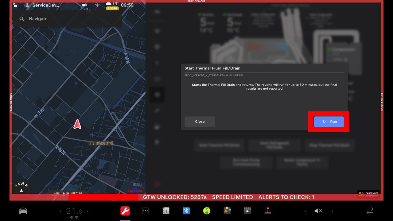
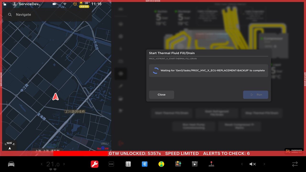
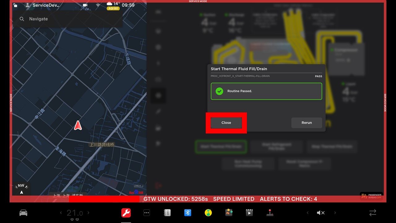
Run Thermal Fill Drain through UI
注Select Thermal > Refrigerant System > Start Thermal Fill Drain , Click Run, Close once routine is completed
-
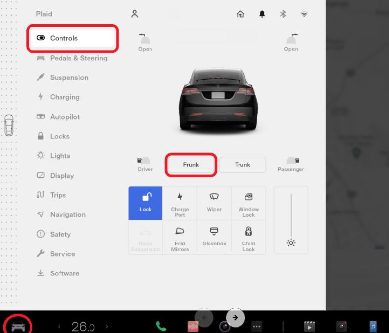
Open the hood.
-
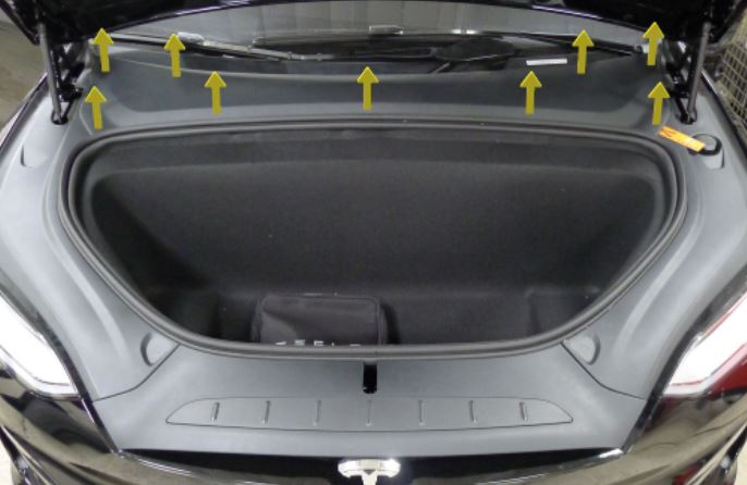
Remove the rear underhood apron.
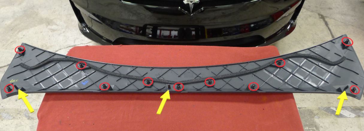
-
Remove the RH underhood apron.
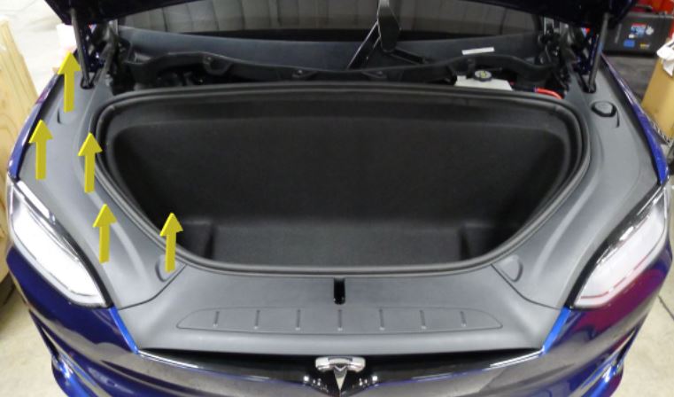
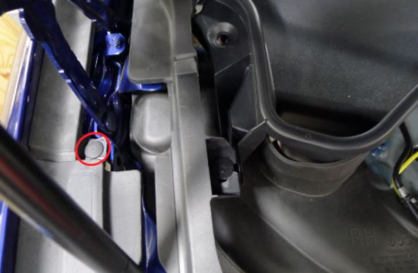
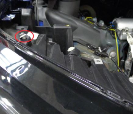
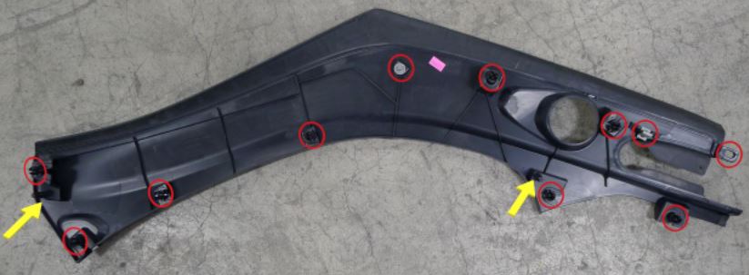
-
Remove the LH underhood apron.

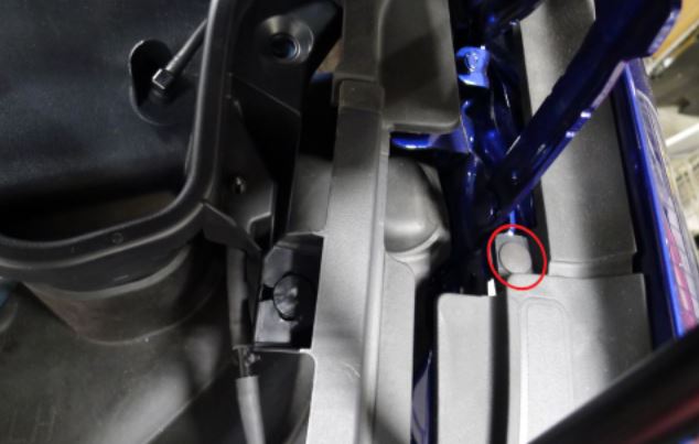
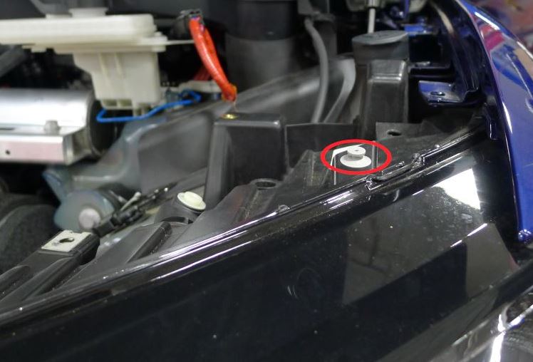
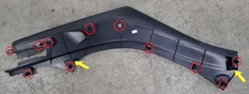
-
Remove the front underhood apron.
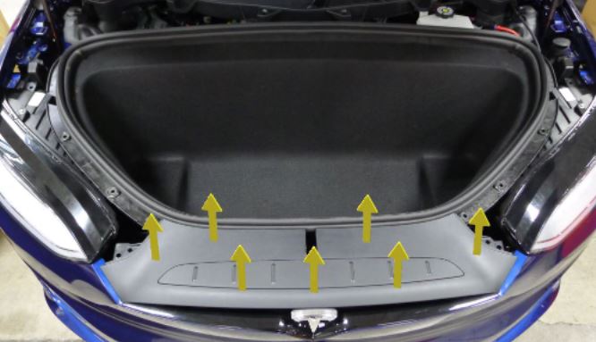
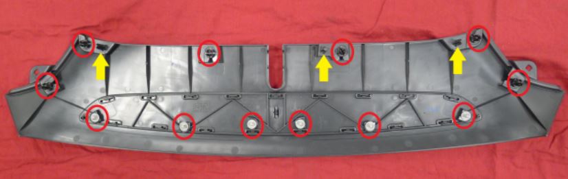
-
Remove the underhood storage unit access panel.
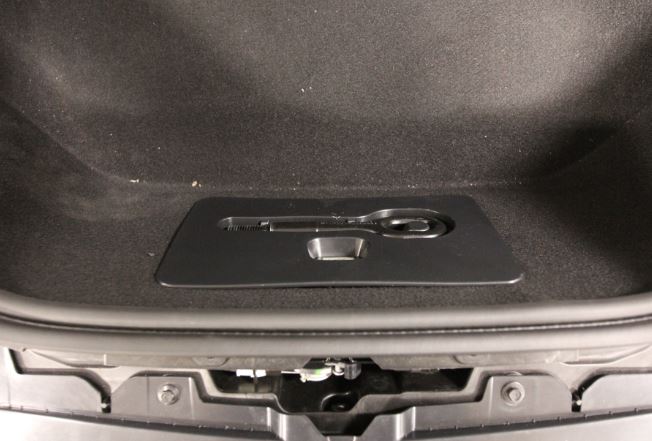
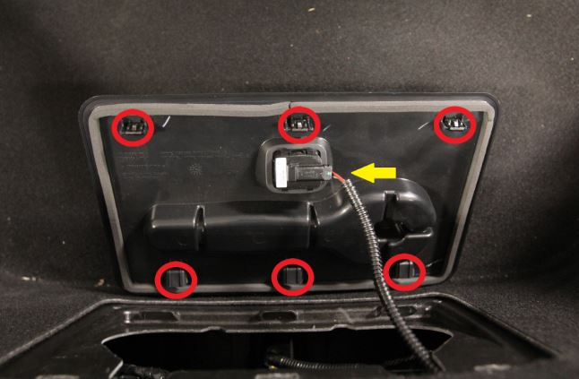
-
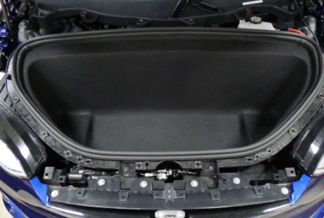
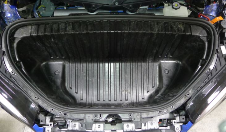
Remove the underhood storage unit carpet.
-
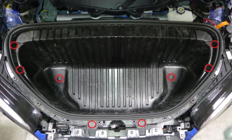
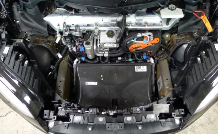
Remove the underhood storage unit from the vehicle.
-
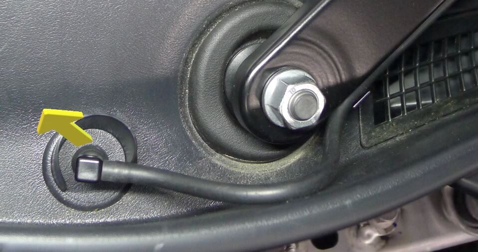
Release RH wiper arm hose nozzle
注1x hose
-
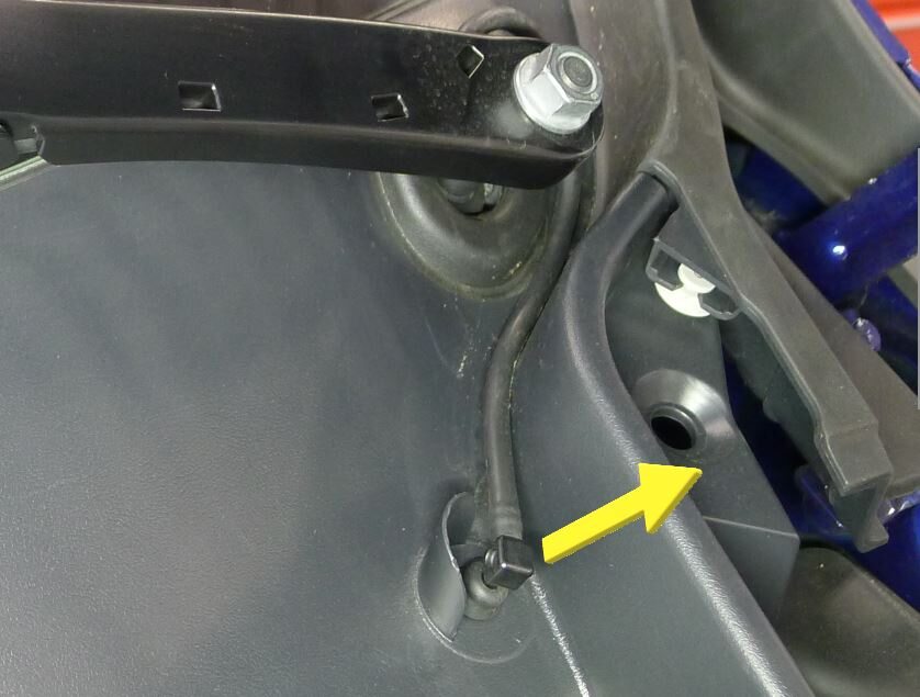
Release LH wiper arm hose nozzle
注1x hose
-
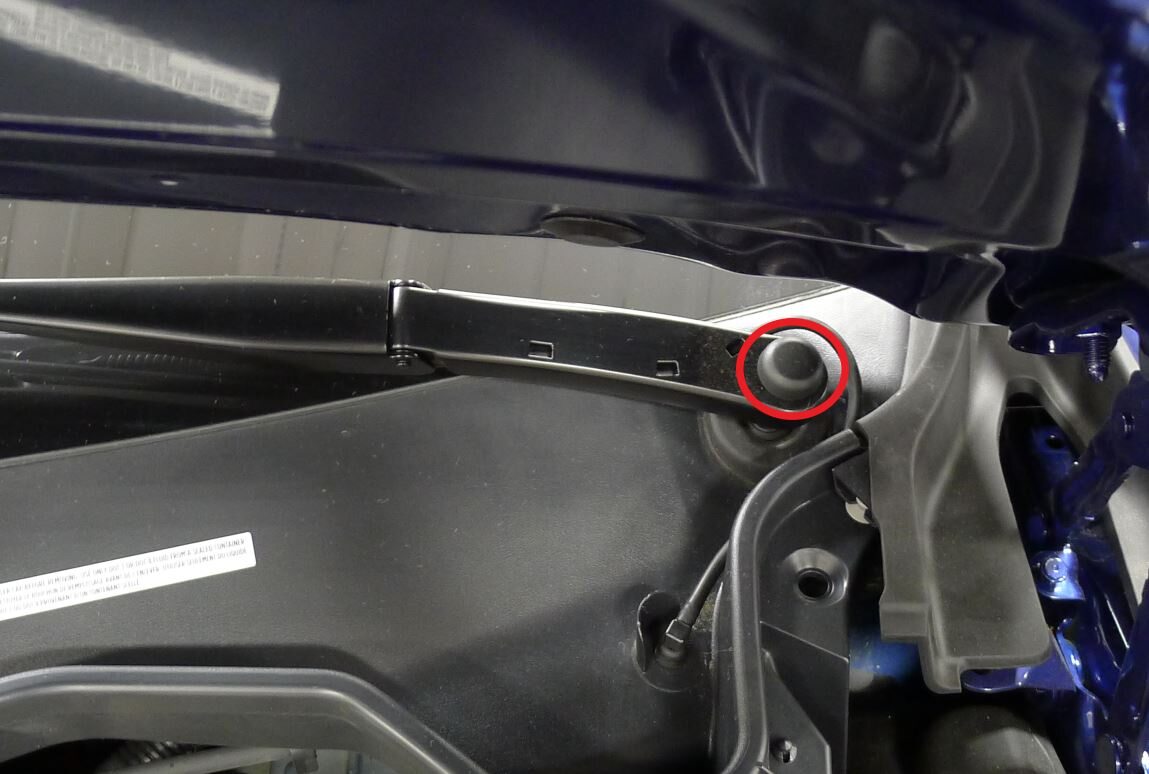
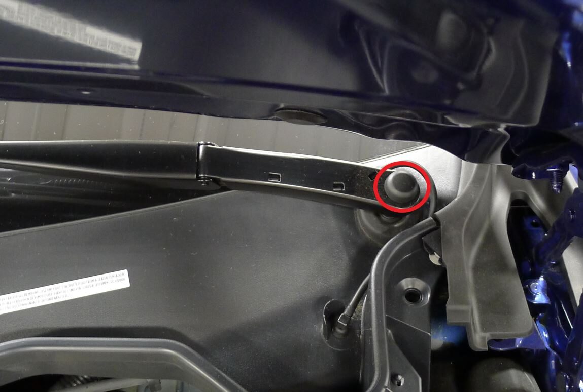
Remove LH wiper arm nut cover
注1x cover
-
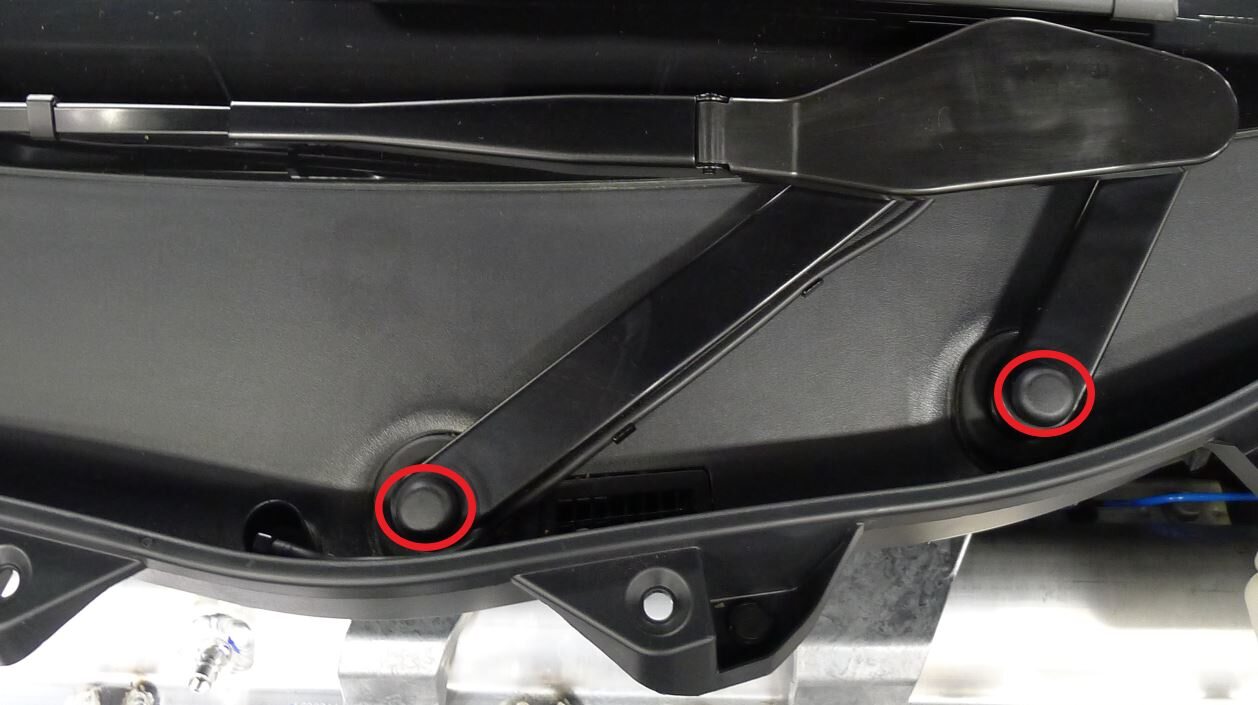
Remove RH wiper arm nut covers
注2x cover
-
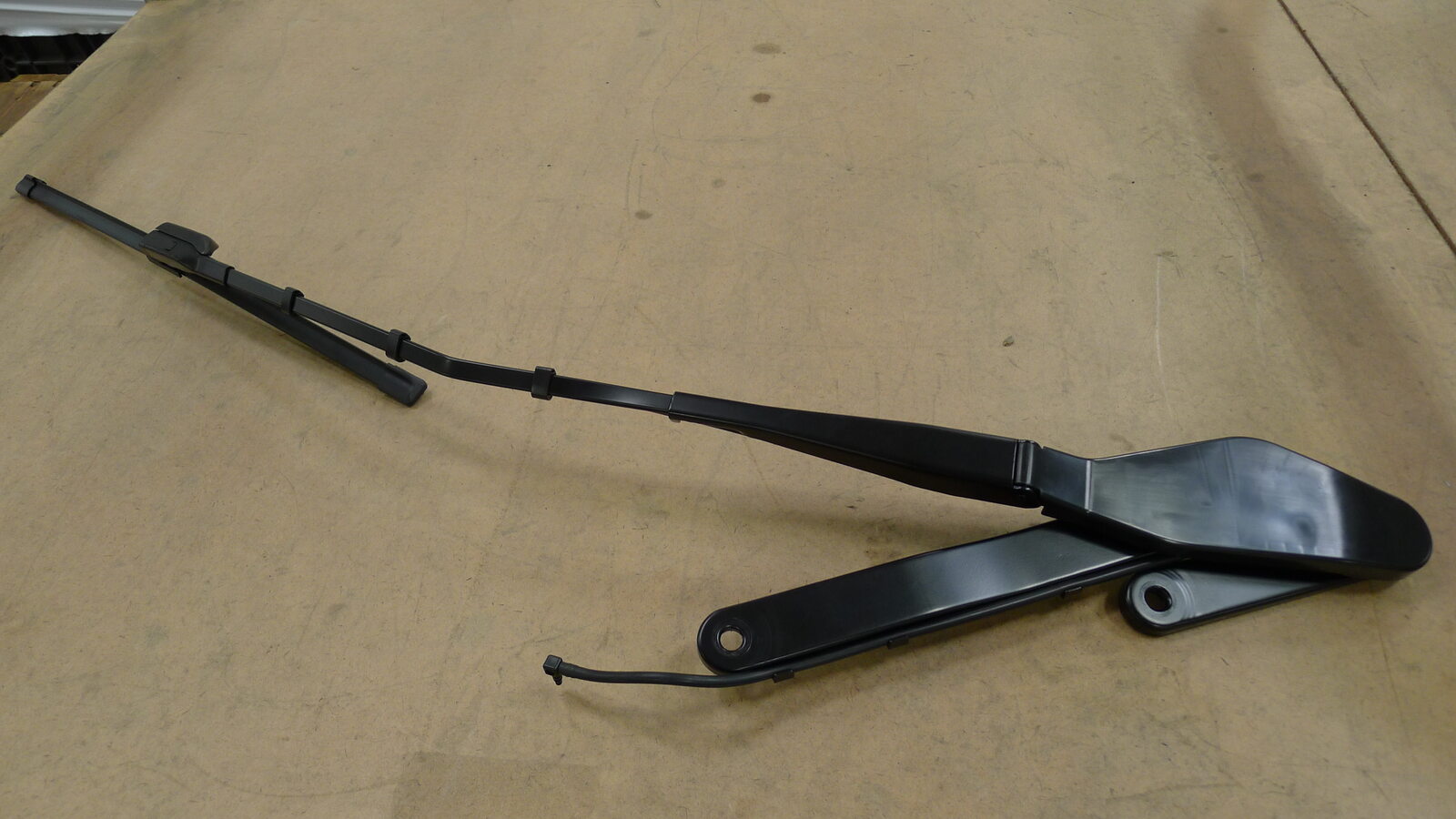
Remove RH wiper arm assembly
注2x nuts, 15mm, 32 Nm, Do not flex wiper arm to remove

-
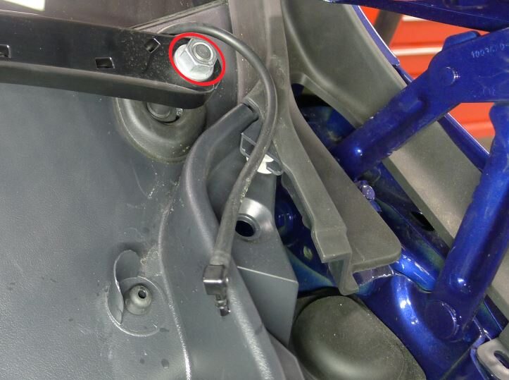
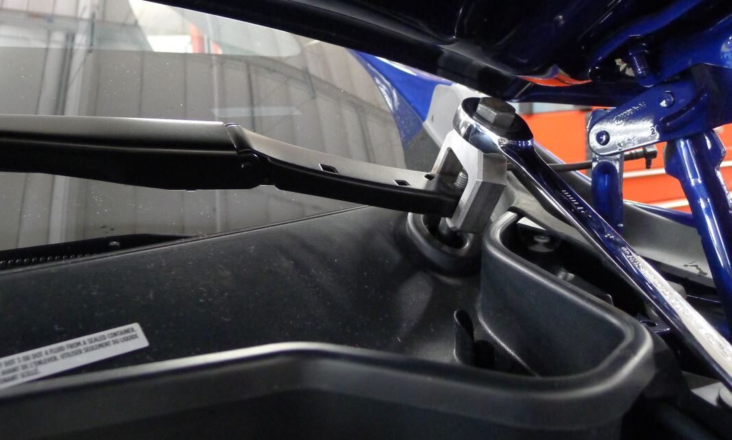
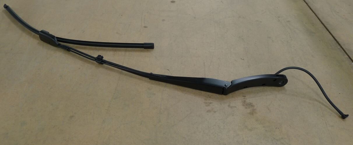
Remove LH wiper arm assembly
注1x nut, 15mm, 32 Nm, Do not flex wiper arm to remove, Lower hood slightly to fit wiper arm removal tool
-
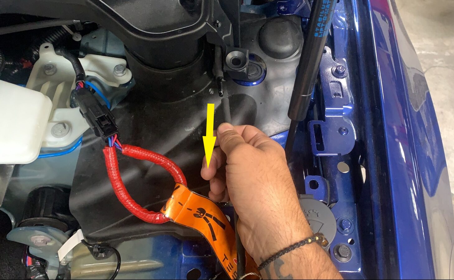
Release cowl screen washer supply hose
注1x hose, located above LH shock tower cover
-
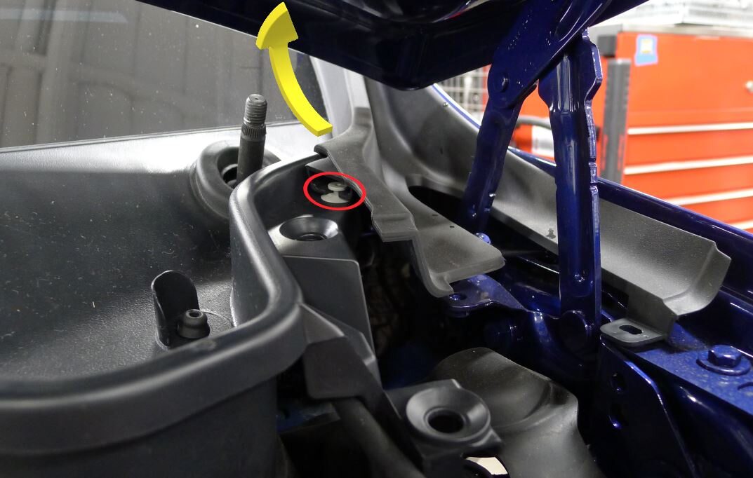
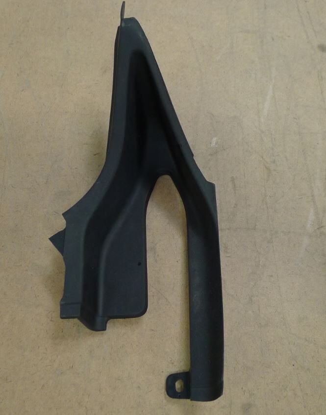
Remove LH outer hood hinge cover
注1x clips
-
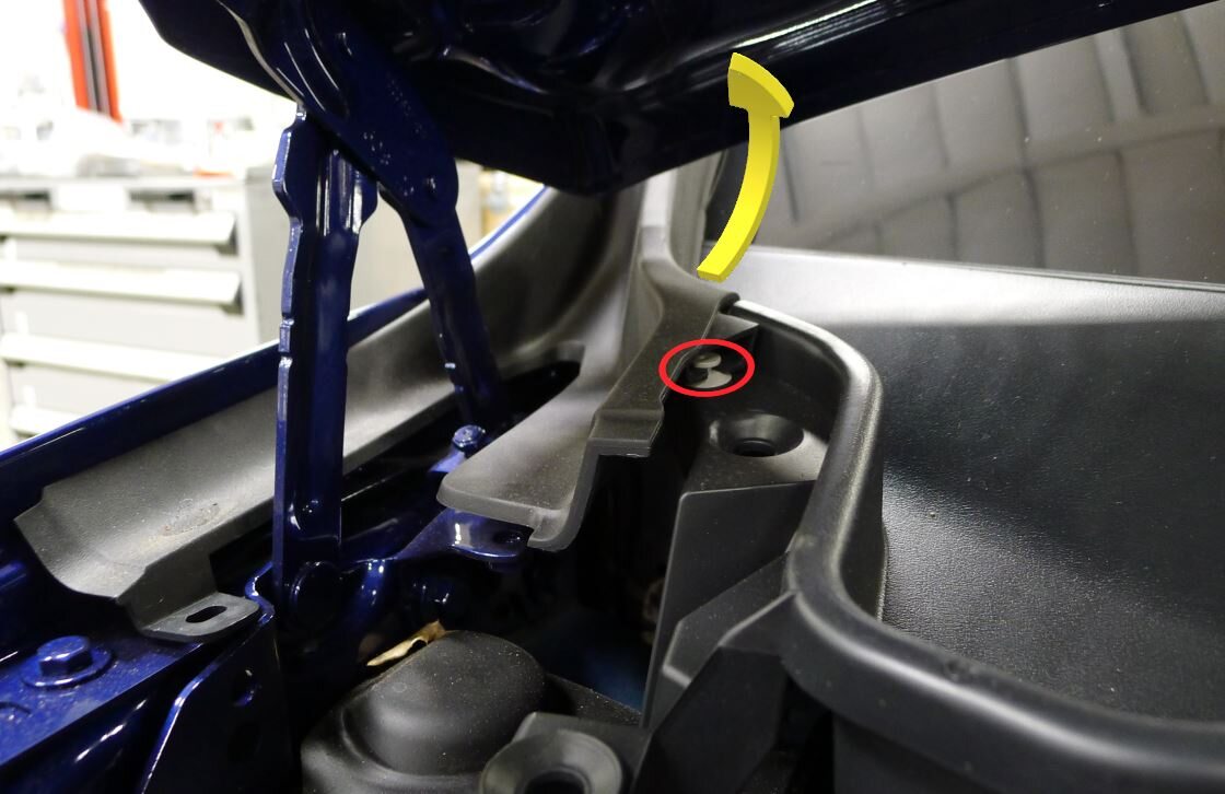
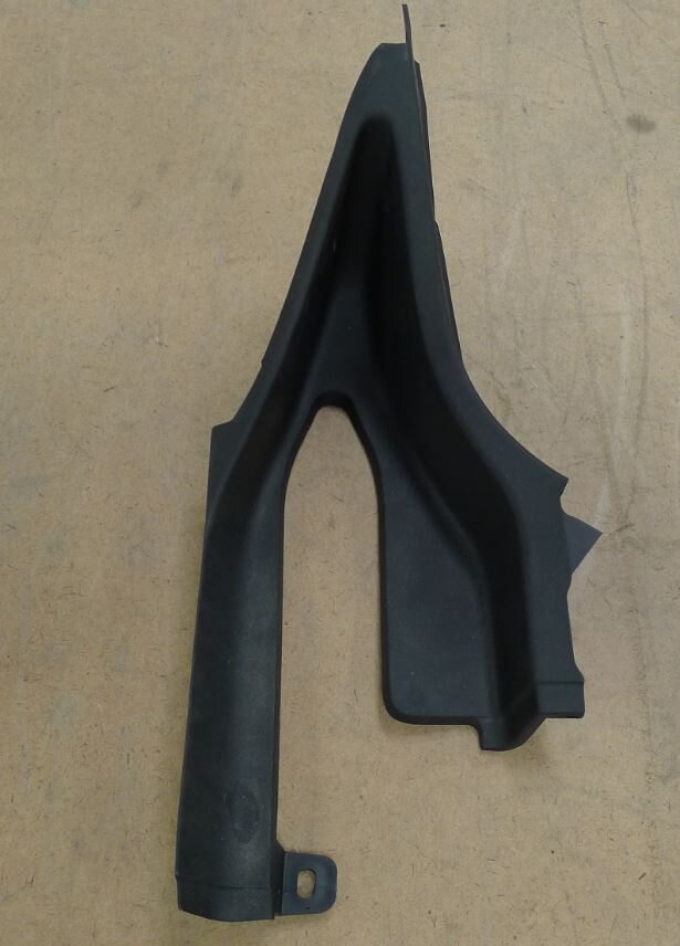
Remove RH outer hood hinge cover
注1x clips
-
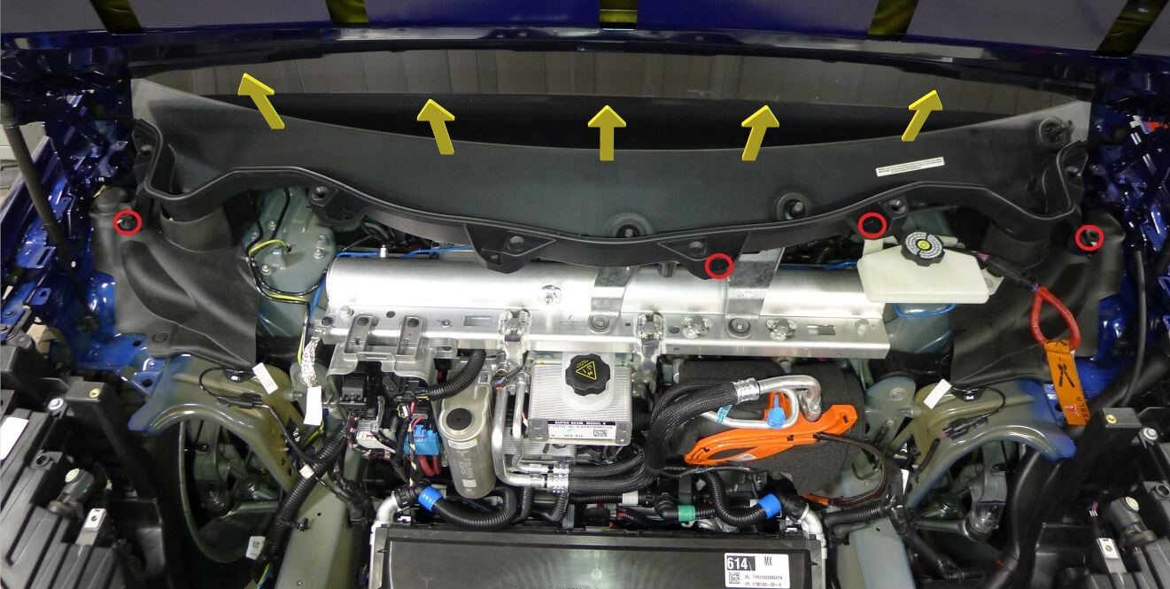
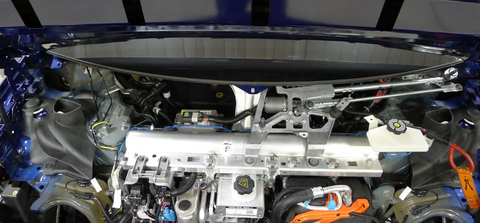
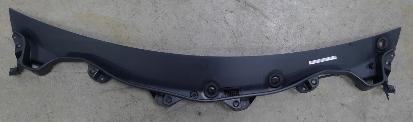
Remove wiper cowl screen panel
注4x push clips, Pull cowl up out of lower windshield channel
-
Move LH front seat forward
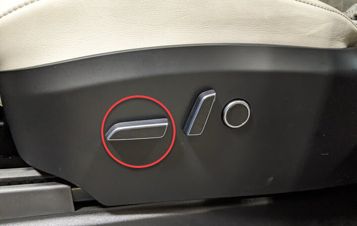
- Move the RH front seat forward.
-
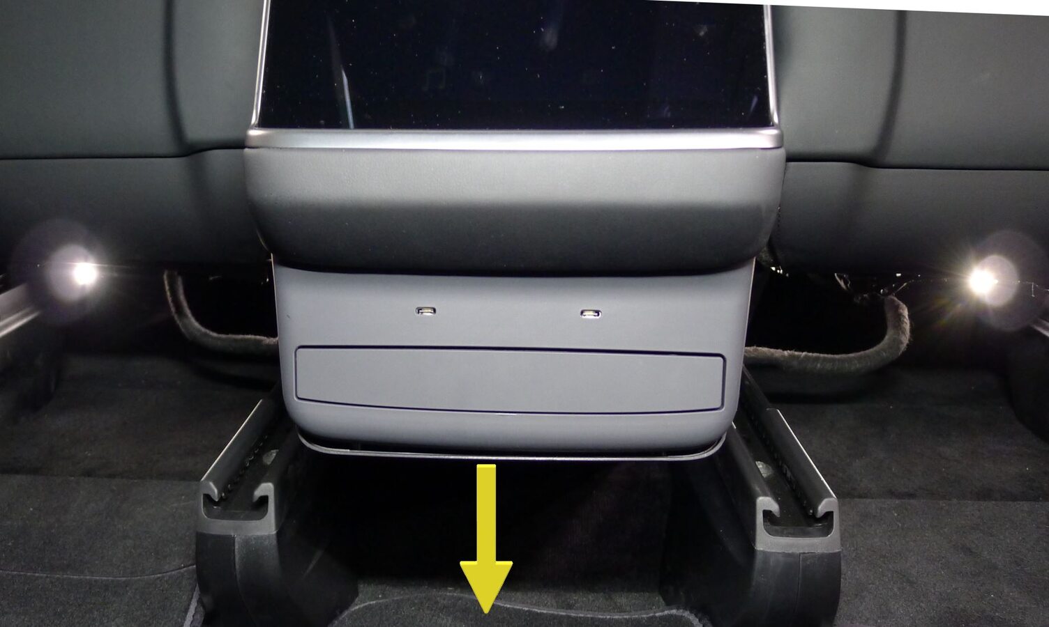
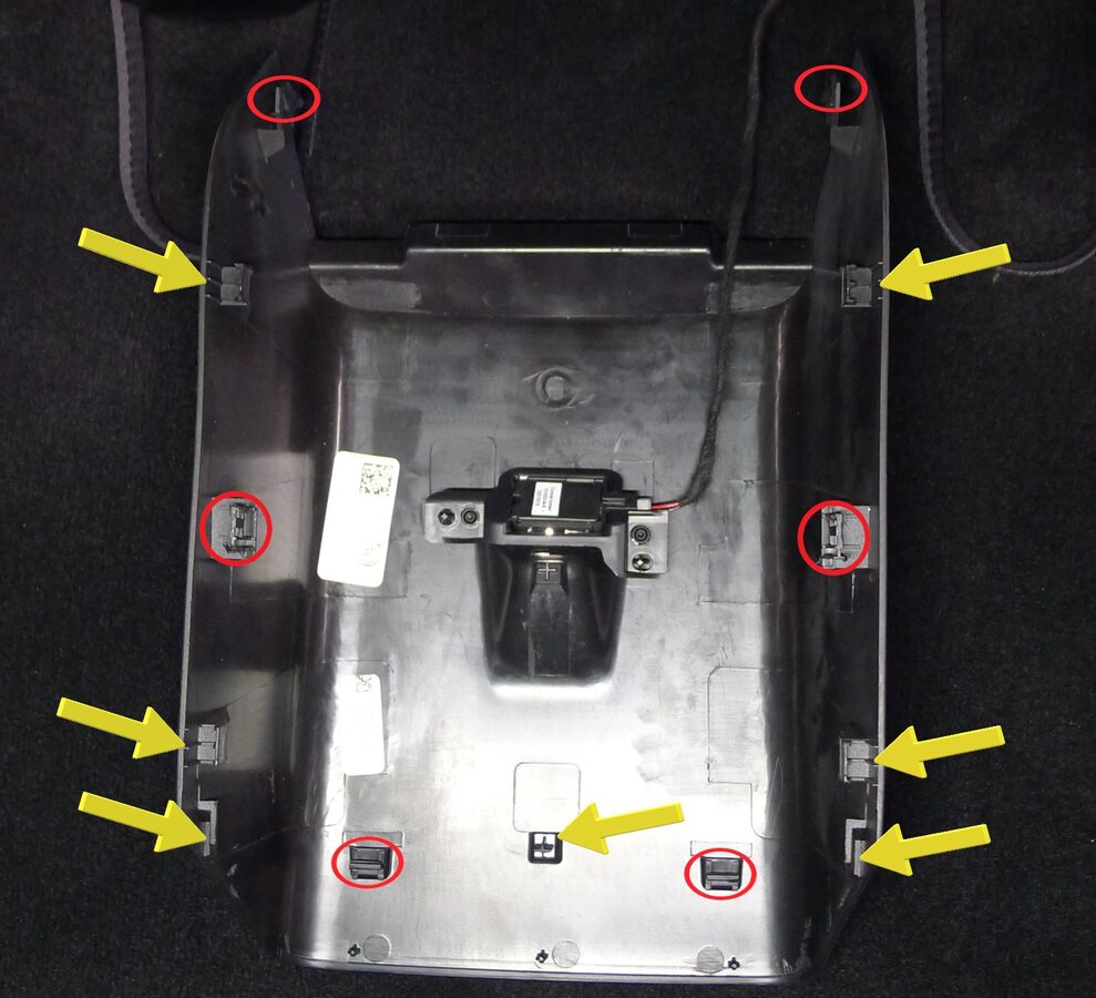
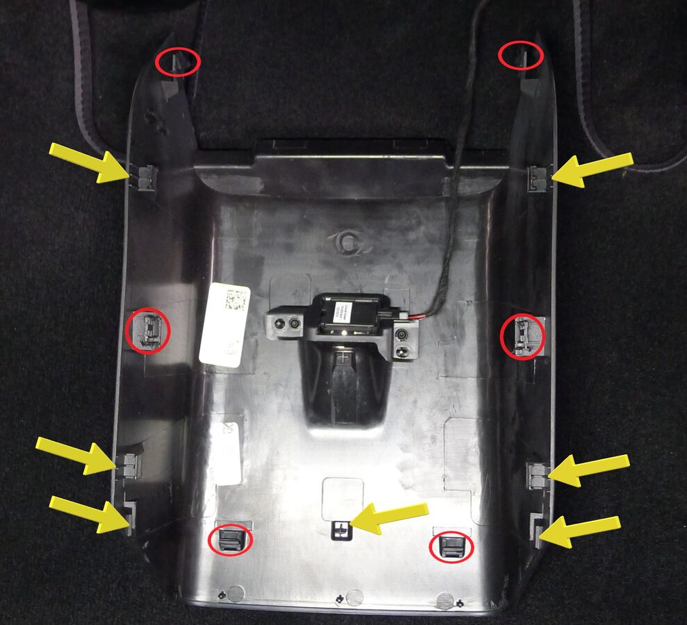
Release console back panel assembly
注6x clips, 7x datums, Disengage bottom clips last and pull rearward due to alignment
-
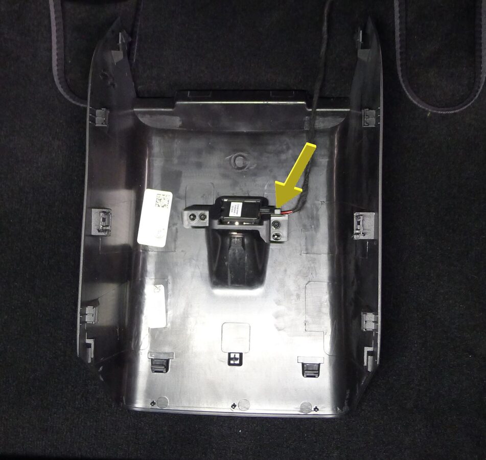
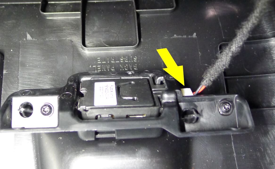
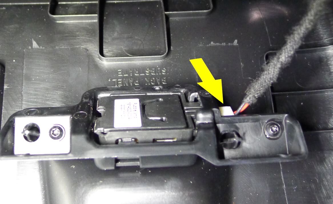
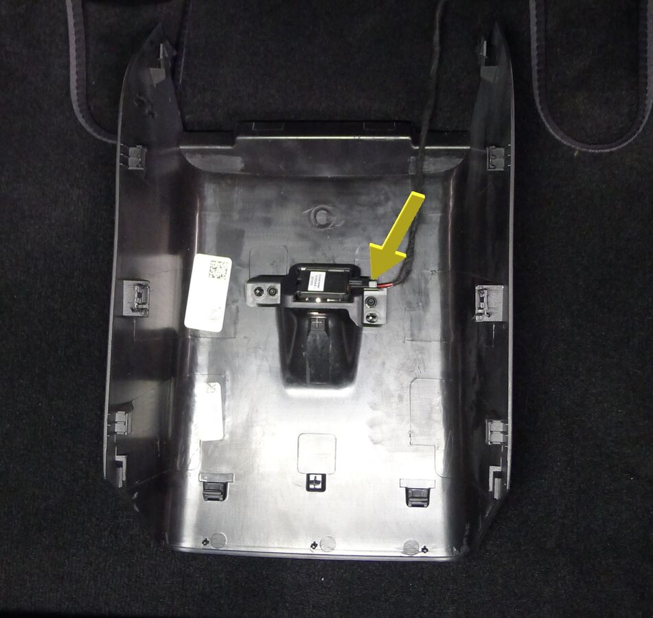
Remove console back panel assembly
注1x connector, Connector lock for lamp located underneath bracket
-
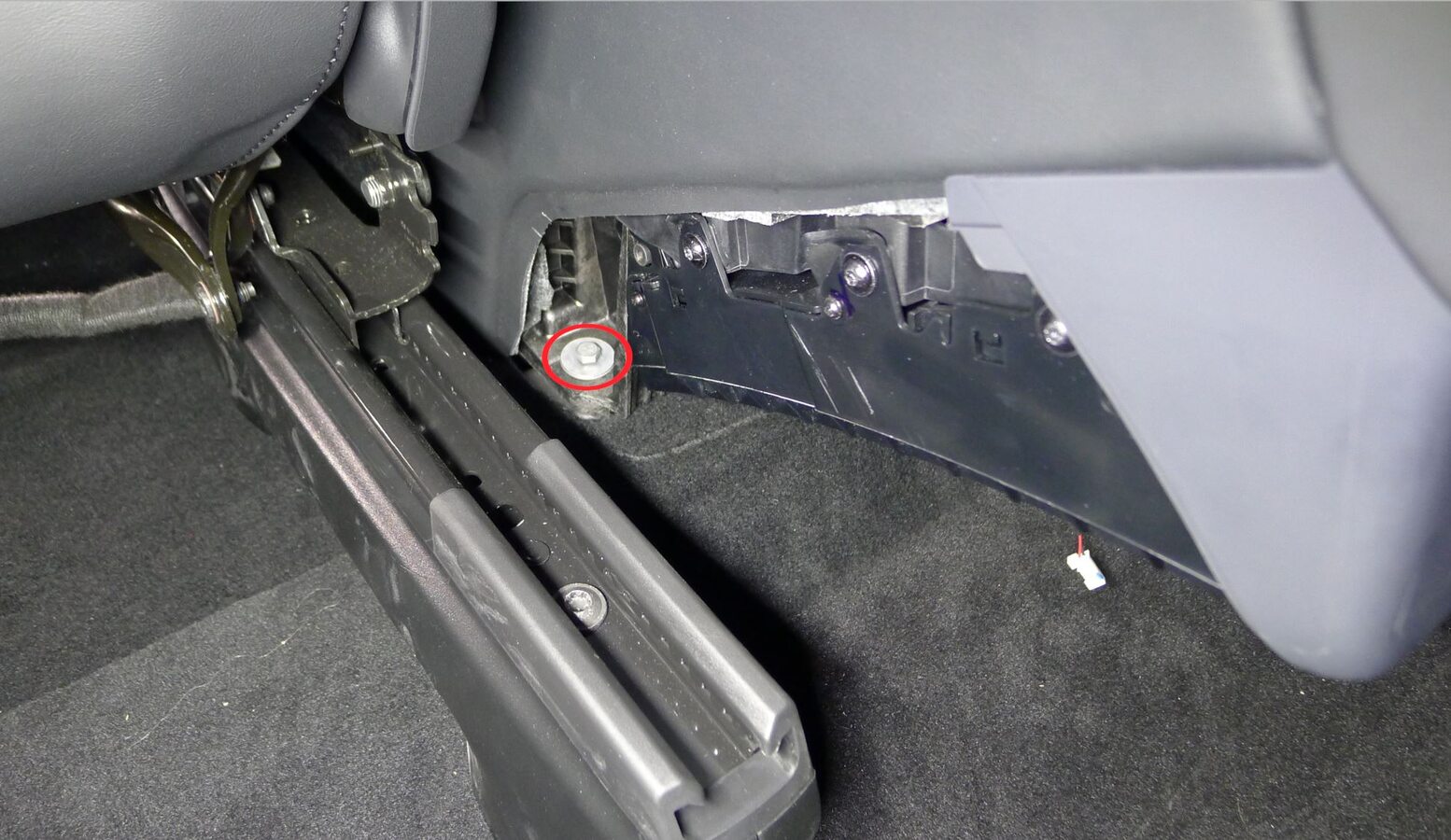
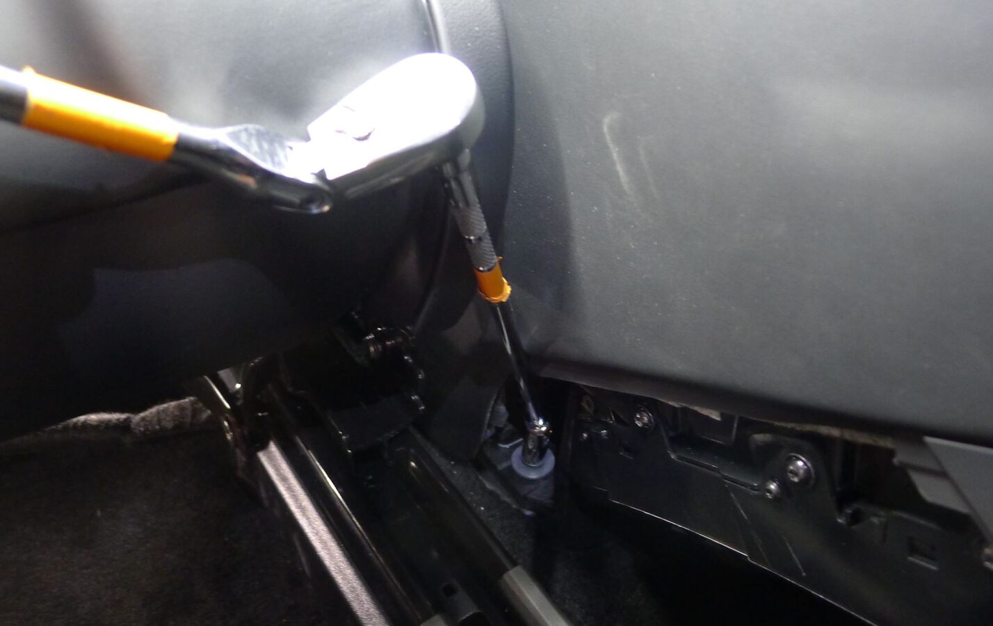
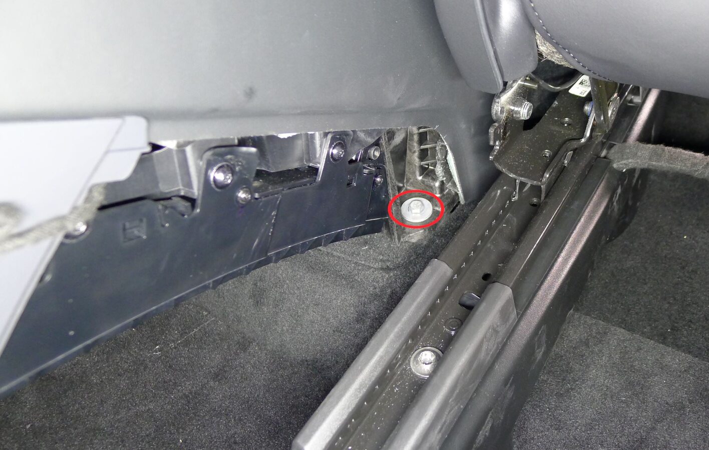
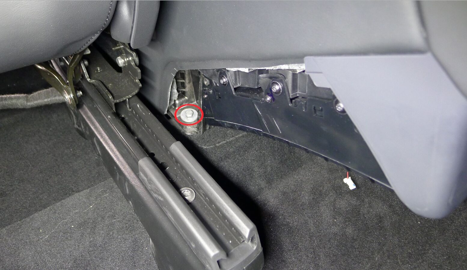
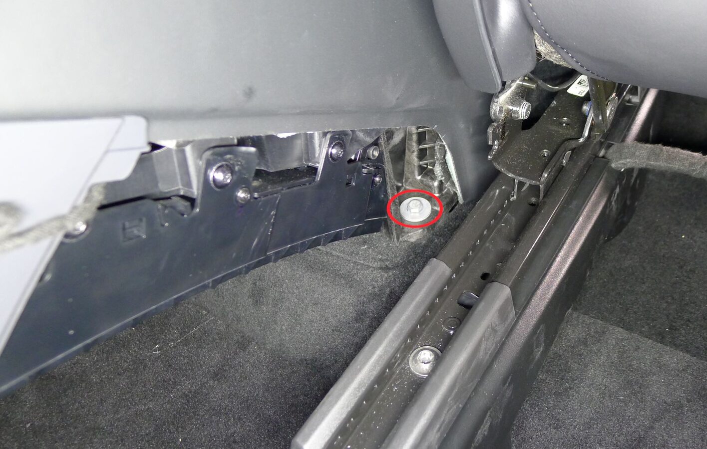
Release LH and RH rear console carrier
注2x bolts, 10mm, 12 Nm
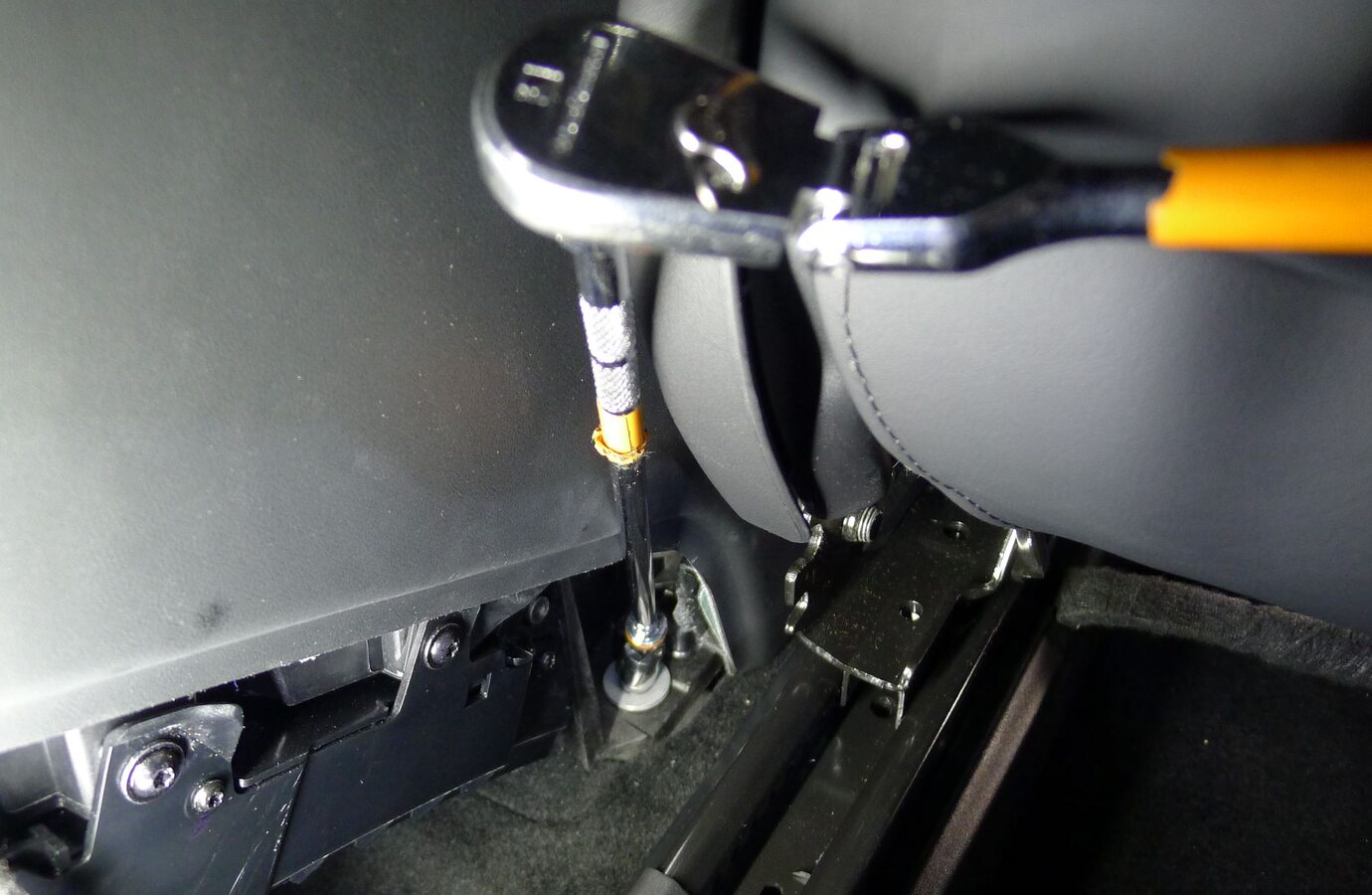
- Move the RH front seat backward.
- Move the LH front seat backward.
-
Remove LH front floor mat
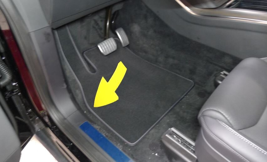
-
Remove LH outboard footwell cover
注2x magnets, 2x datums
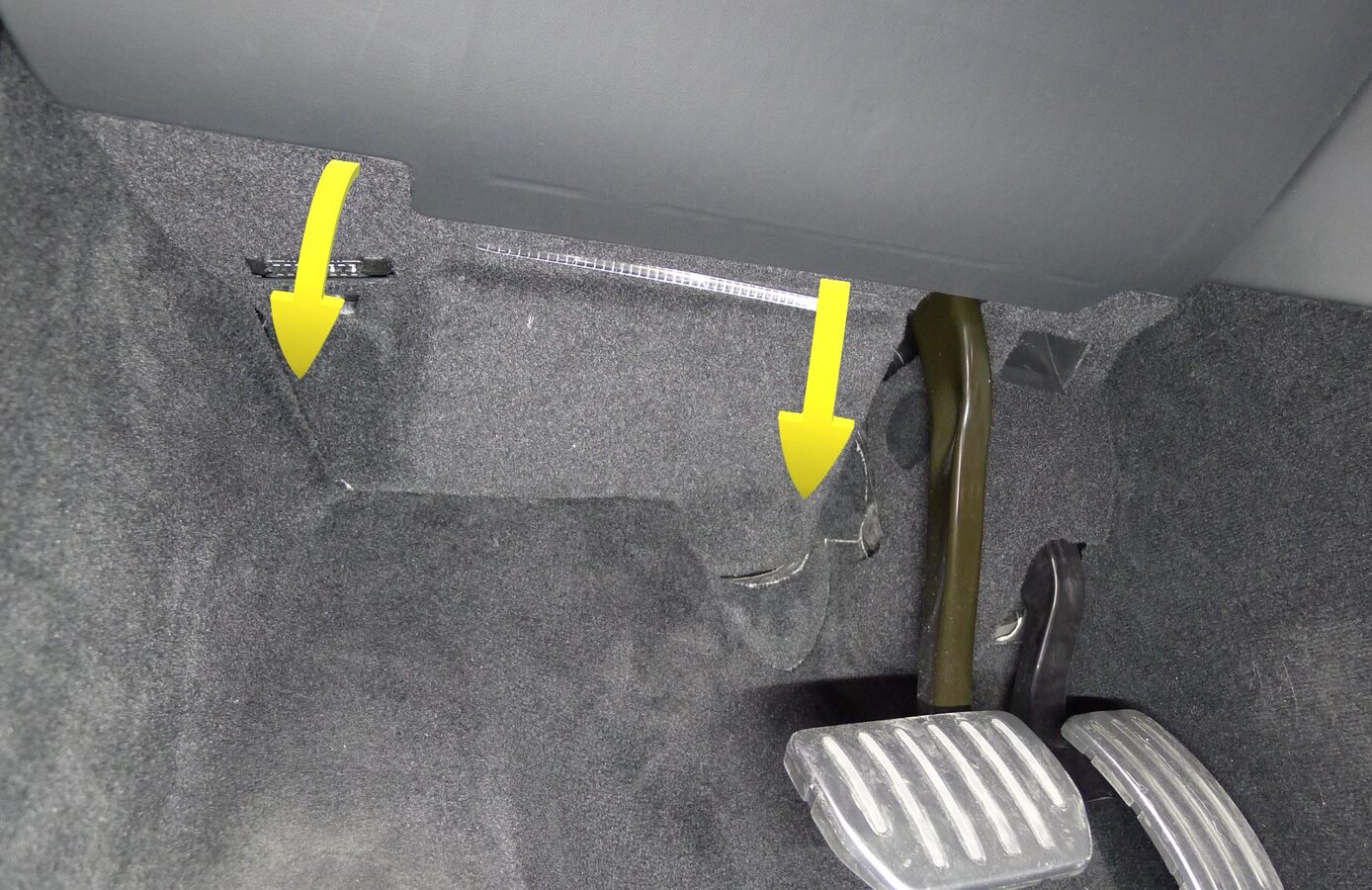
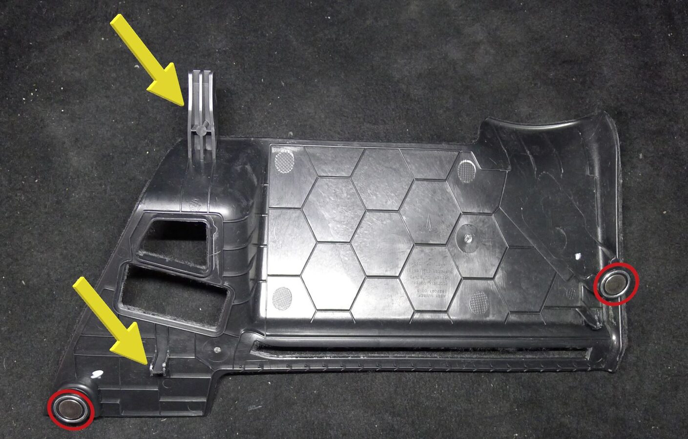
-
Remove LH inboard footwell cover
注1x cover, 1x clip, 1x datum, 1x screw, 8 mm, 1 Nm
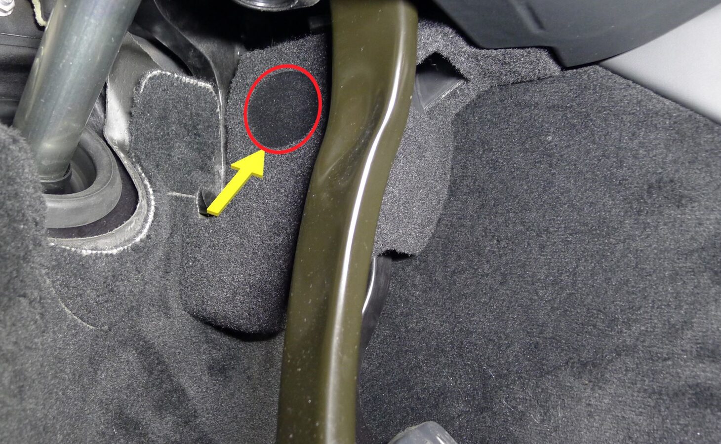
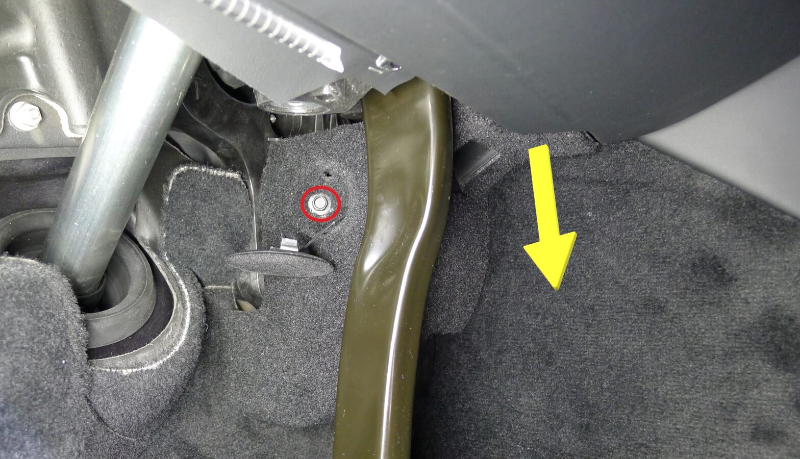
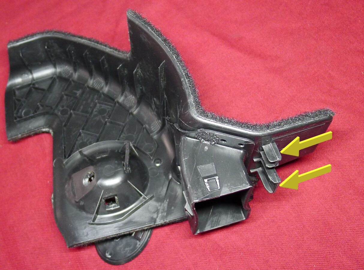
-
Remove LH console side carpet
注11x clips, 2x datums

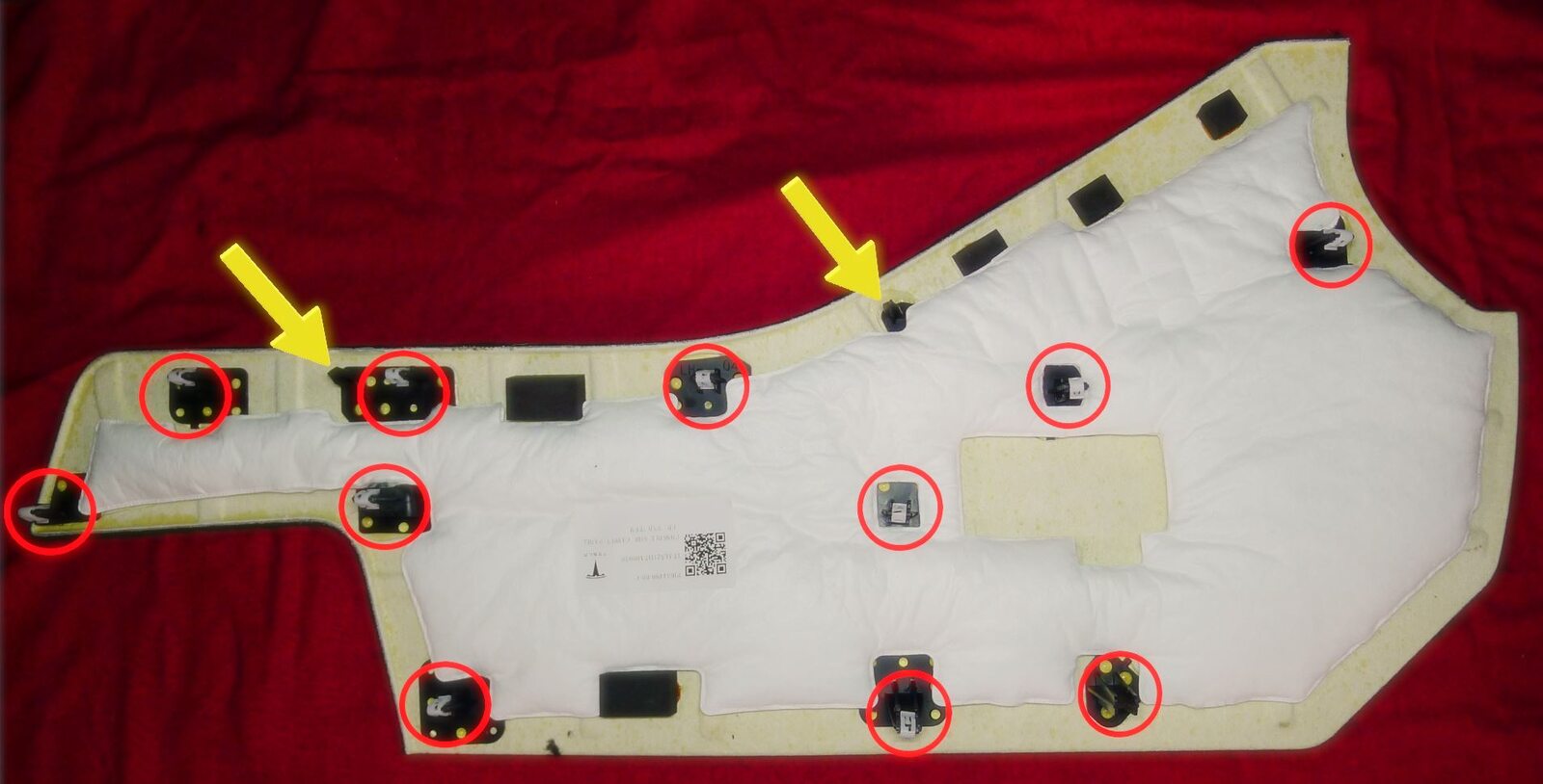
-
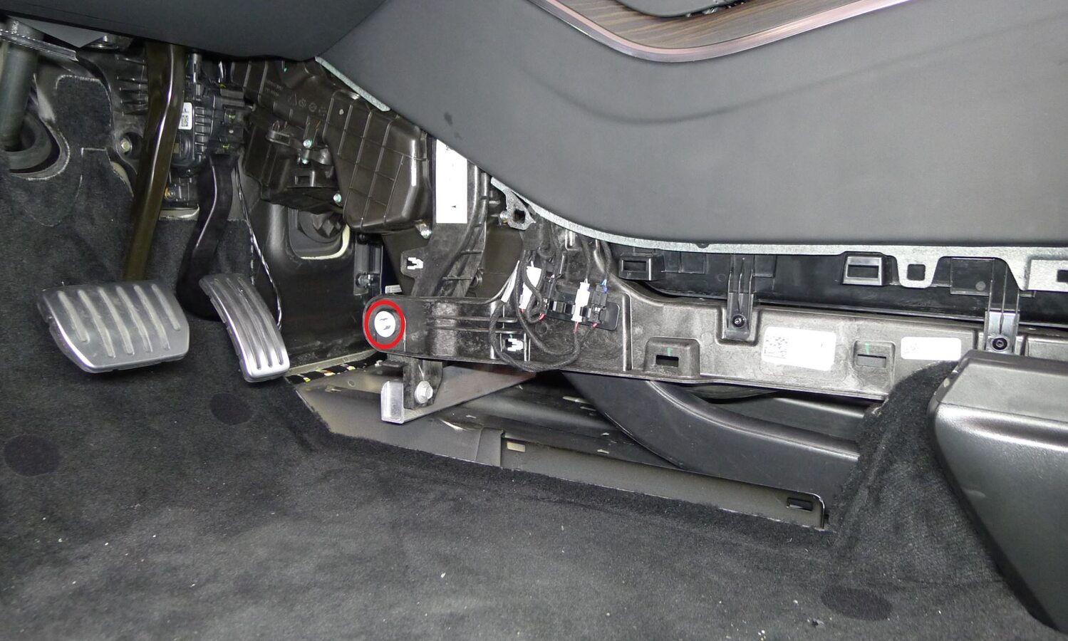
Release LH center console lower bracket from IP carrier
注1x bolt, 10mm, 10 Nm
-
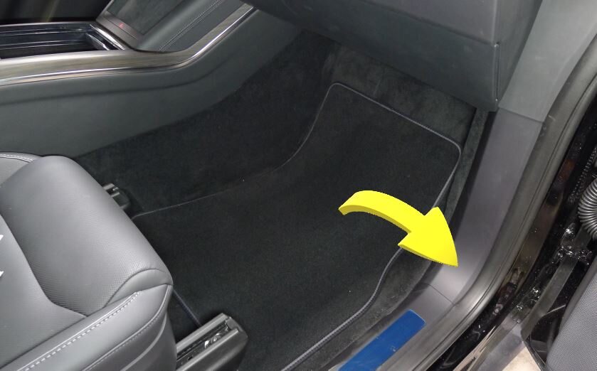
Remove RH front floor mat
-
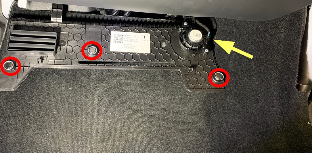
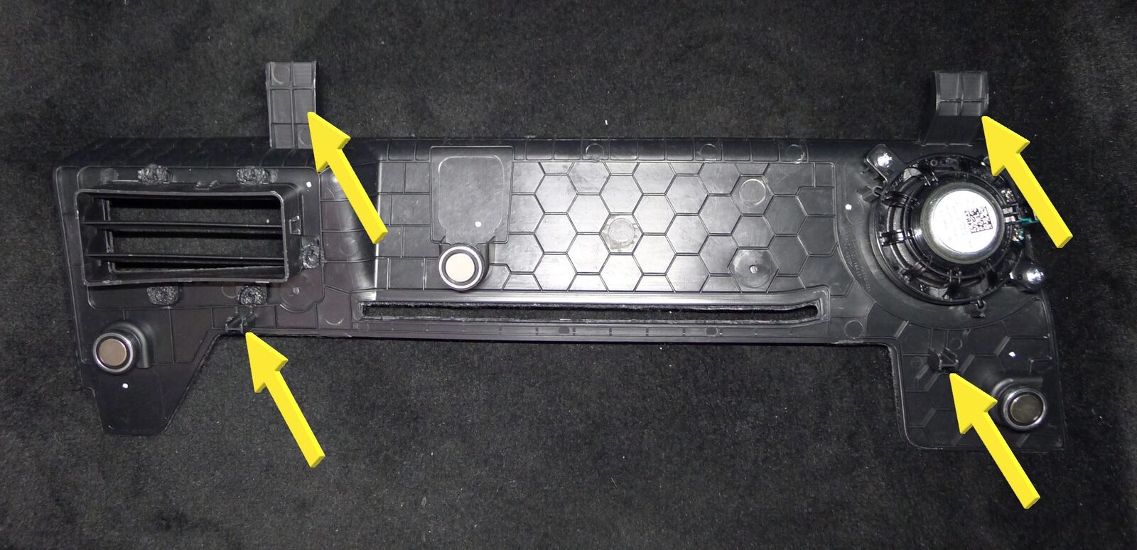
Remove RH footwell cover
注3x magnets, 1x connector, 4x datums
-
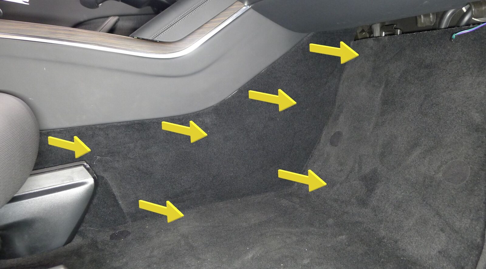
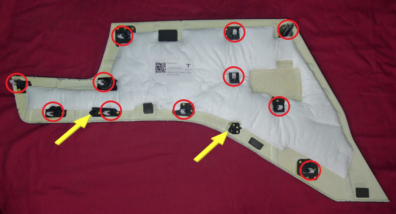
Remove RH console side carpet
注11x clips, 2x datums
-
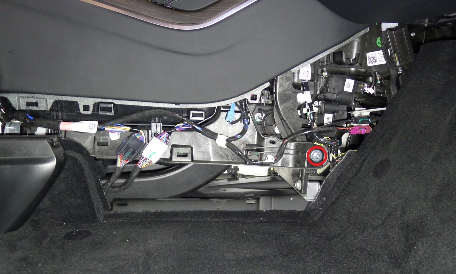
Release RH center console lower bracket from IP carrier
注1x bolt, 10mm, 10 Nm
-
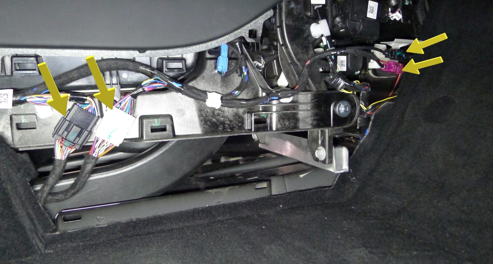
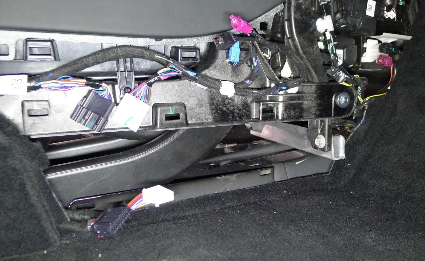
Release center console connectors to body harness
注4x connectors
-
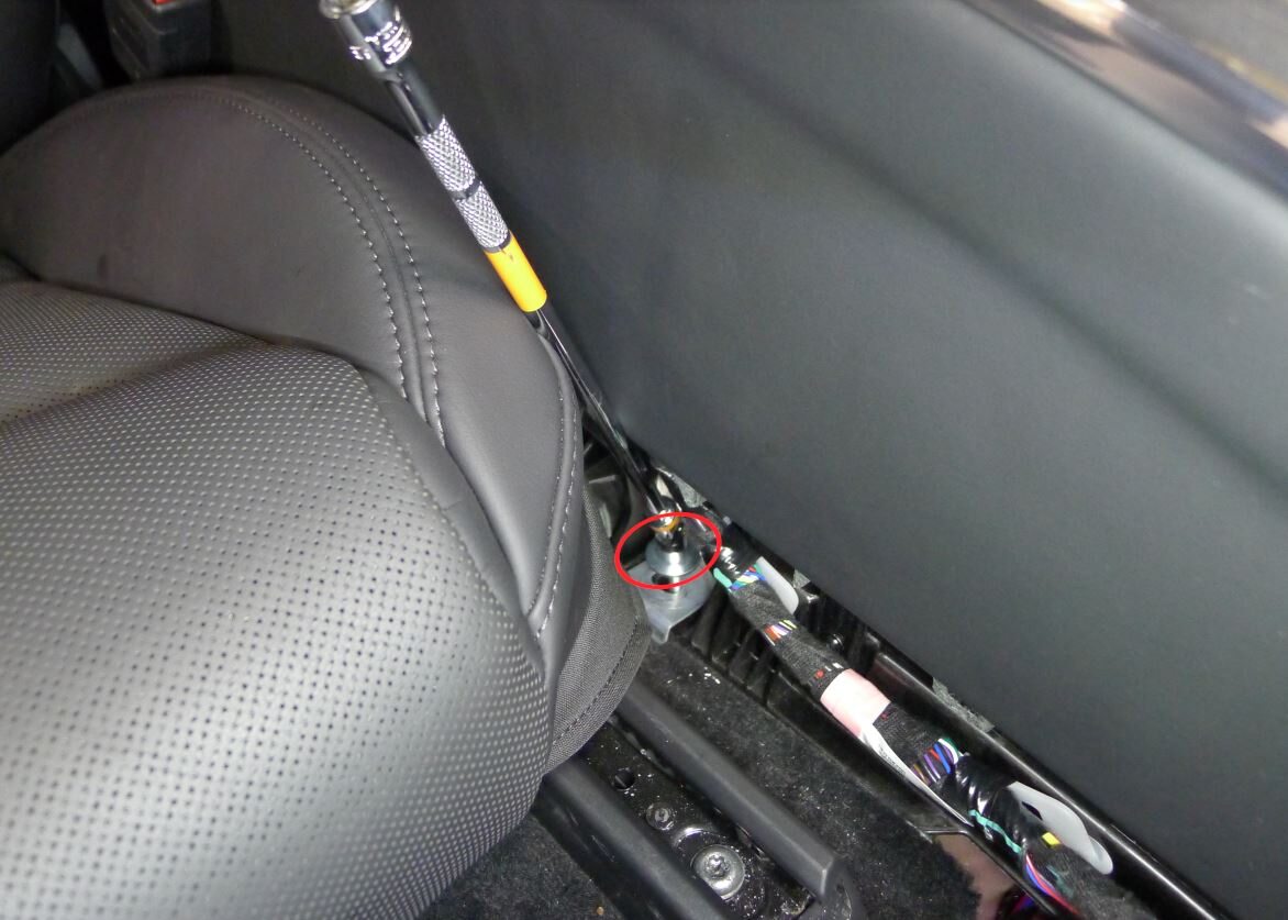
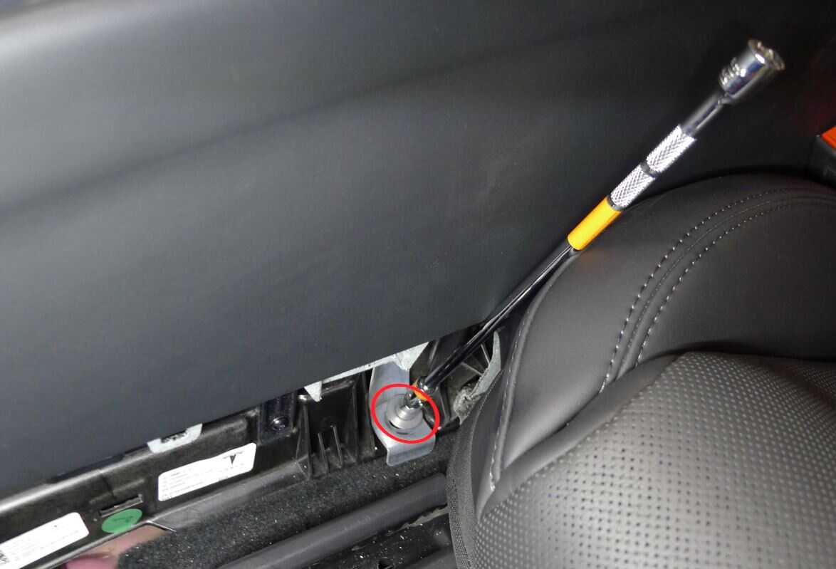
Release LH and RH console carrier center bracket
注2x bolts, 10mm, 12 Nm
-
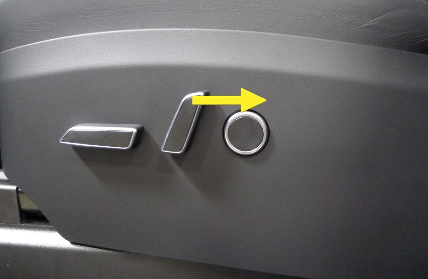
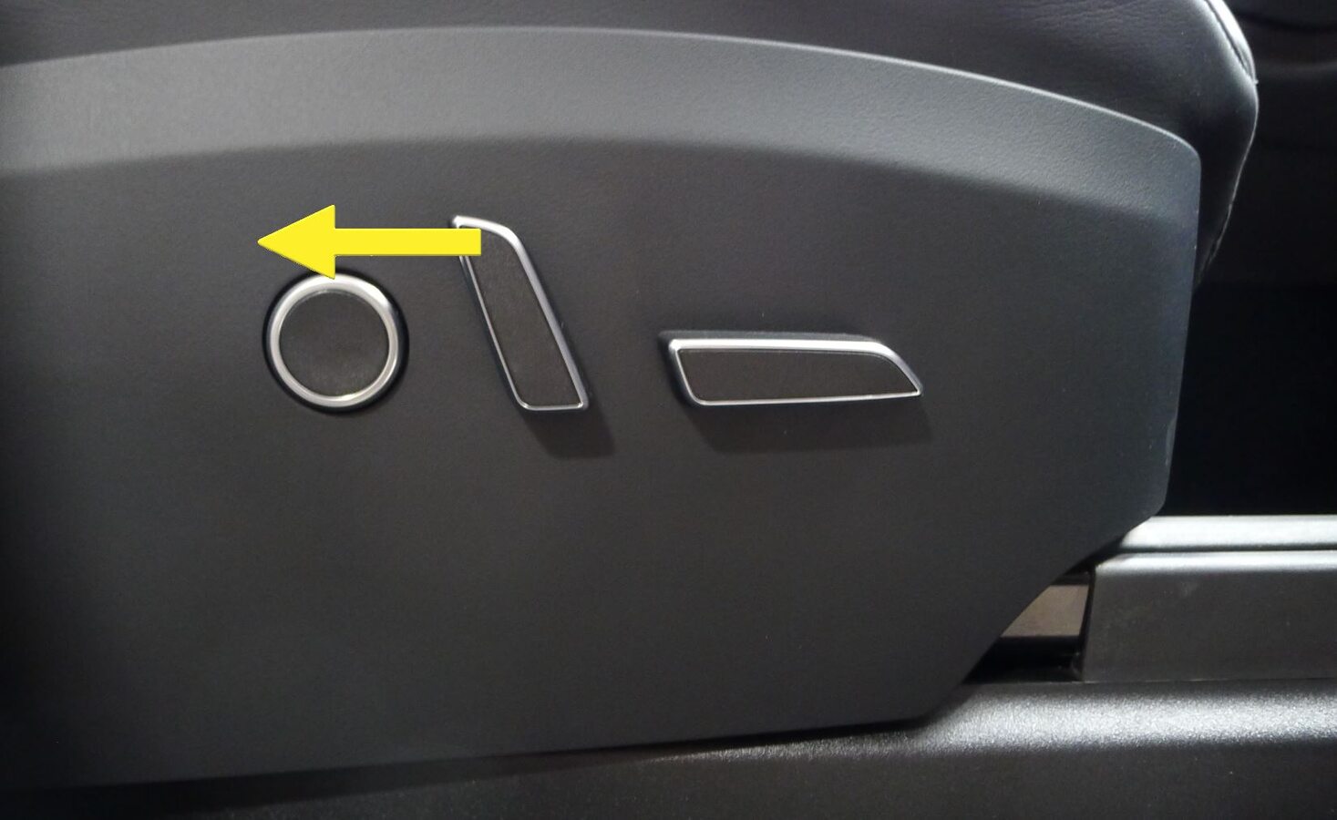
Recline LH front seat backrest
-
Recline RH front seat backrest
-
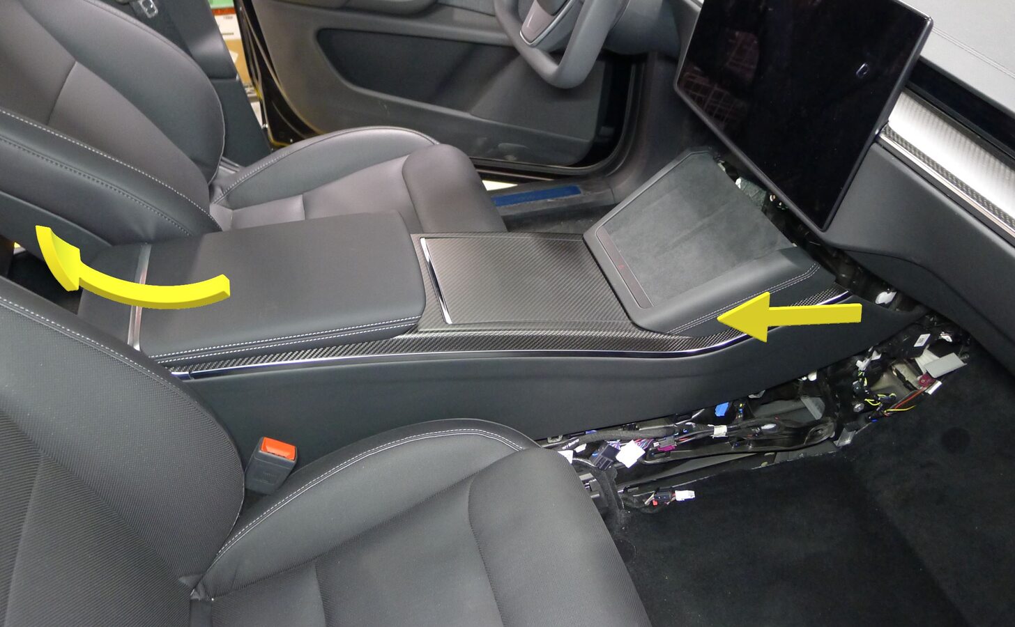
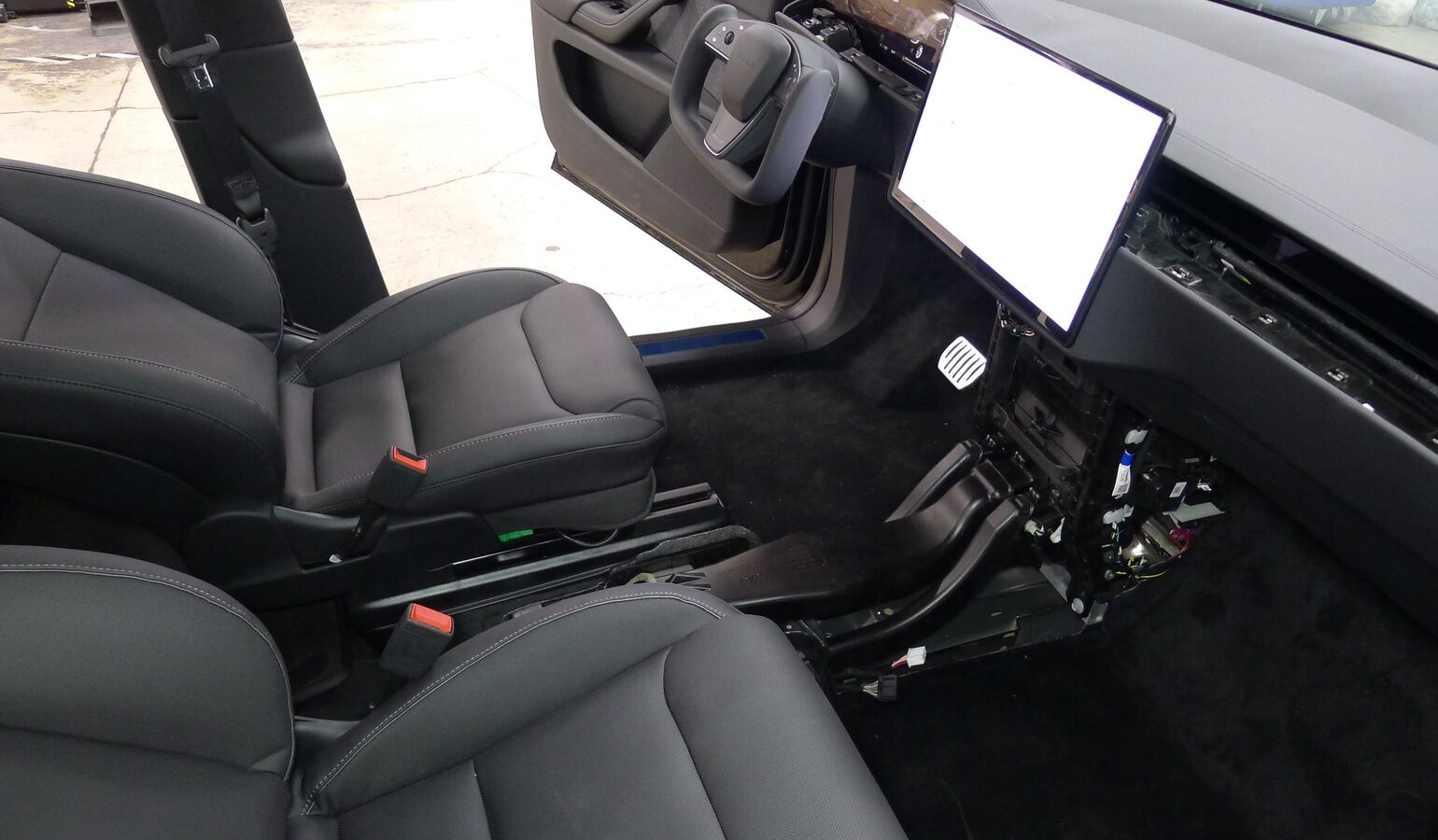
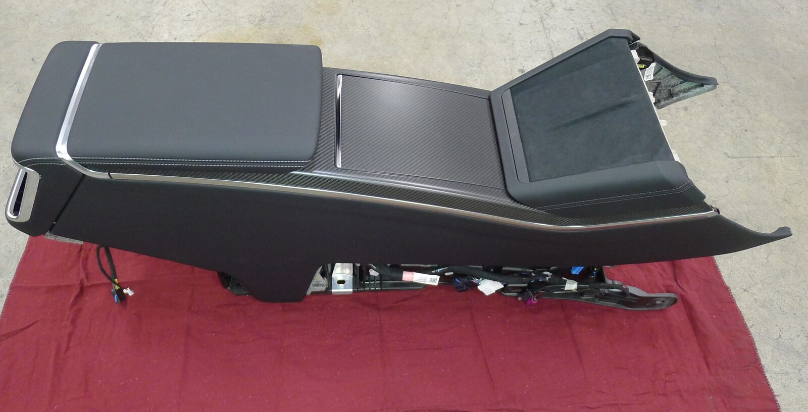
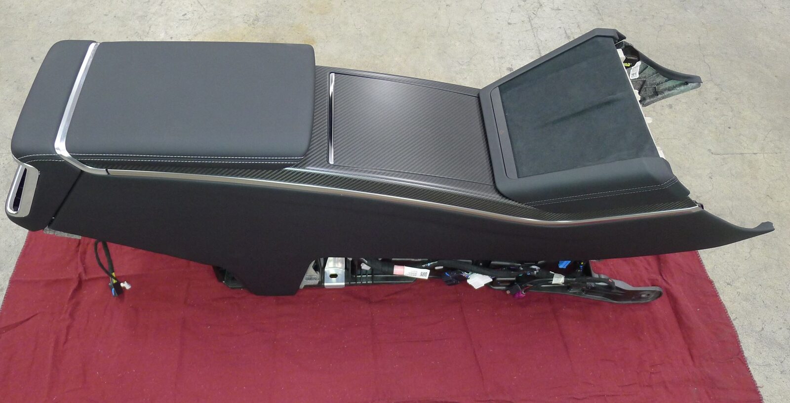
Remove console assembly
注Lift at rear, rotate front from under IP and out passenger door, Take care not to scratch seats, IP or inner door panel, Recommend assistance if needed
-
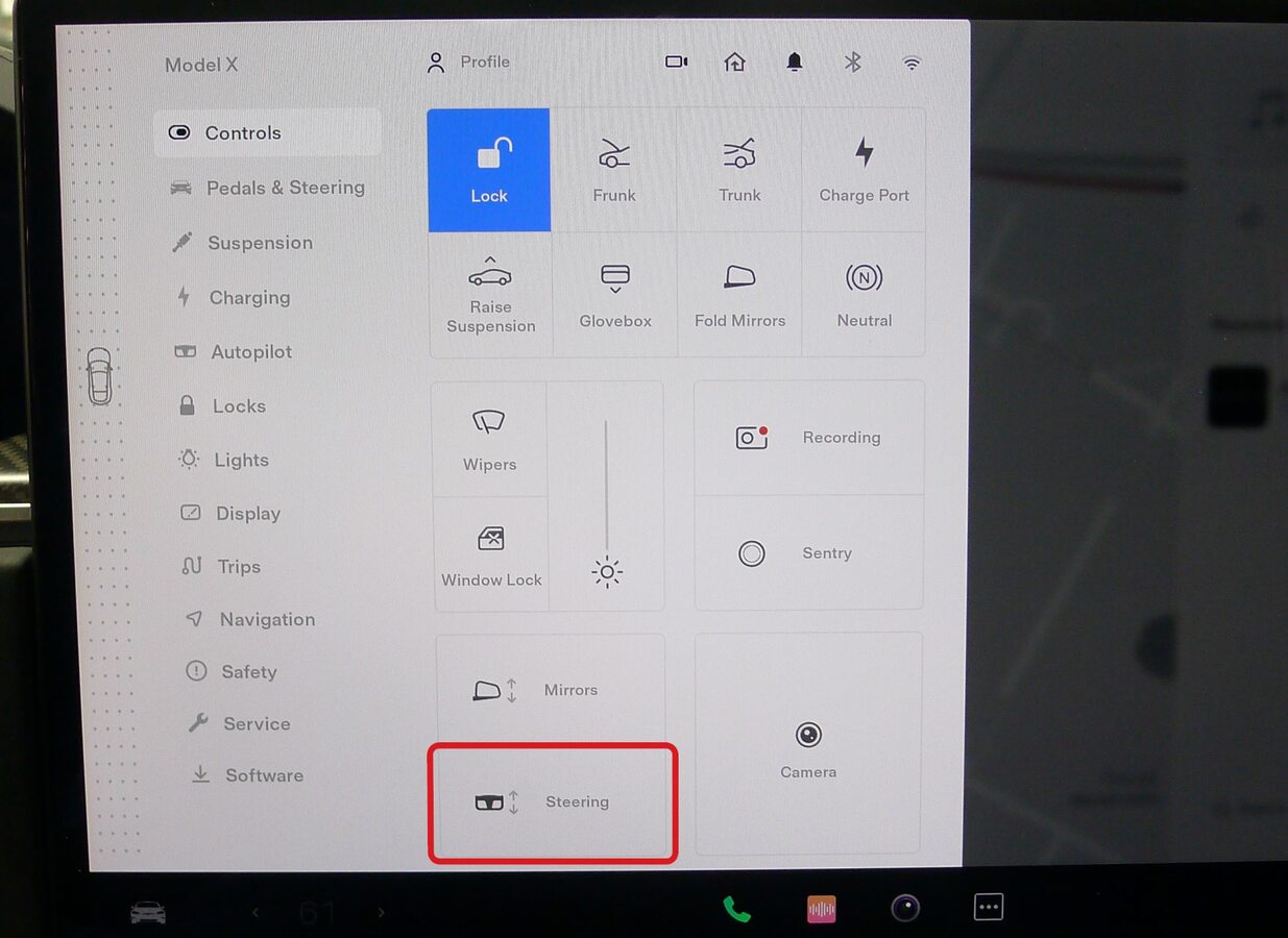
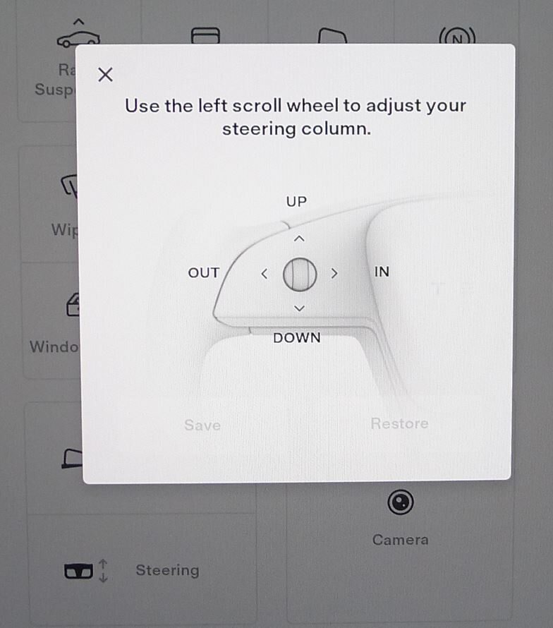
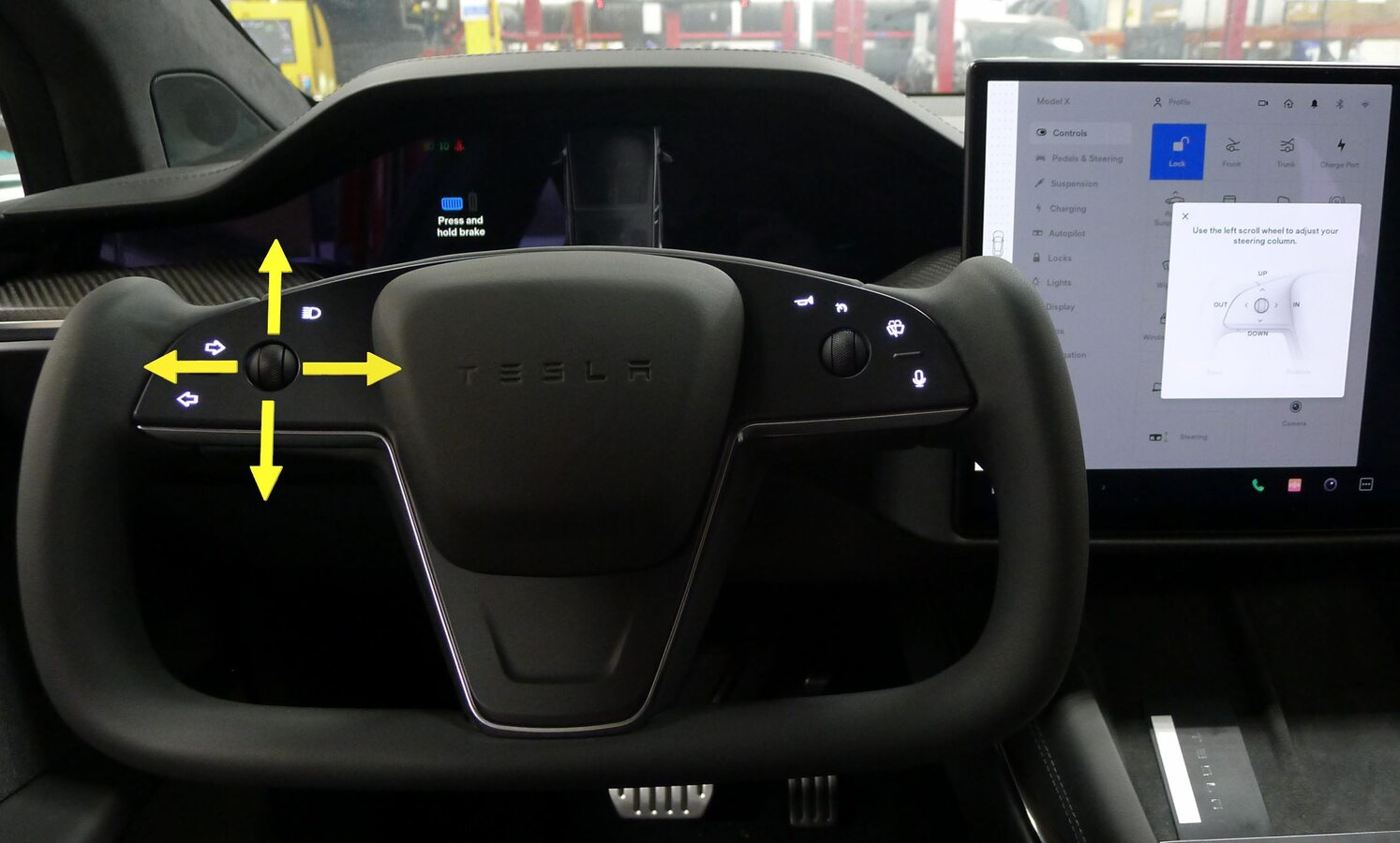
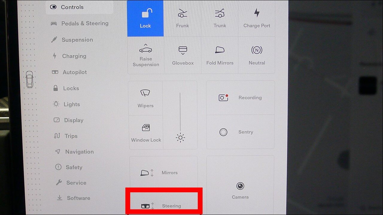
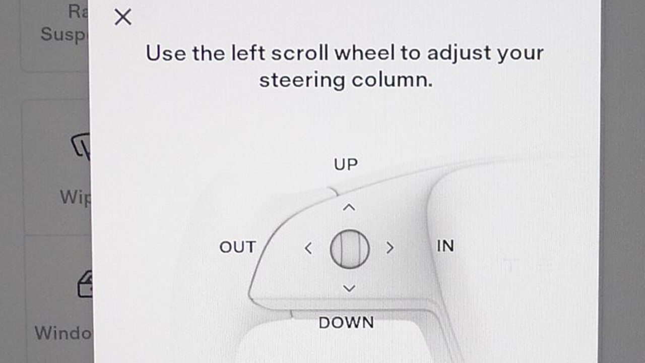
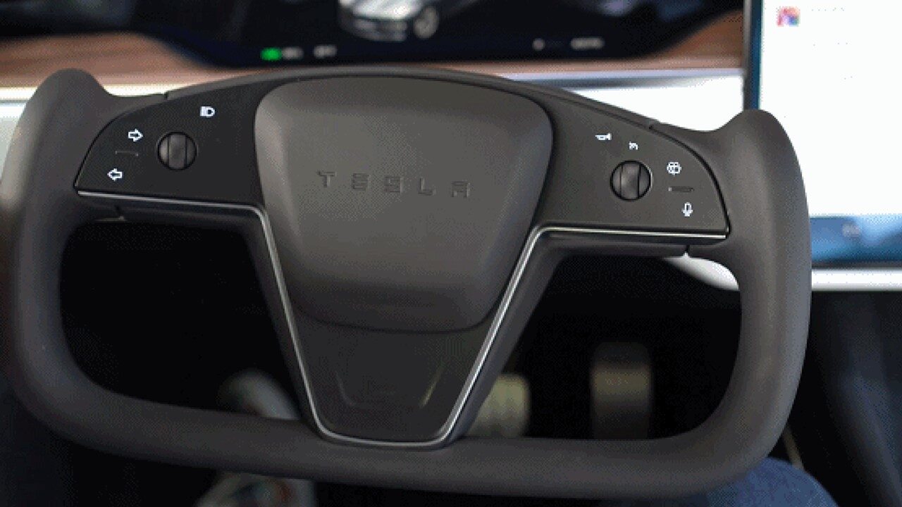
Adjust steering column fully out and fully down
注Via UI > Controls > Steering , Use left steering wheel scroll wheel to adjust steering column
-
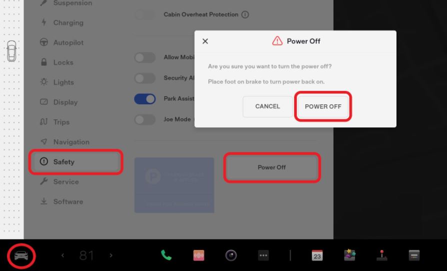
Power off the vehicle using the touchscreen.
-
Disconnect the LV battery connector and First Responder Loop.
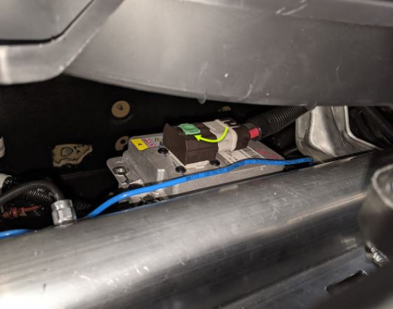
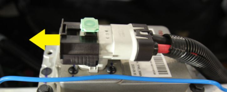
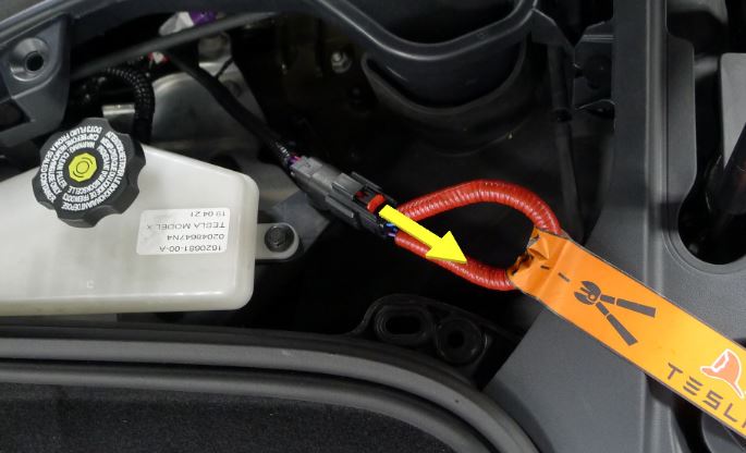
-
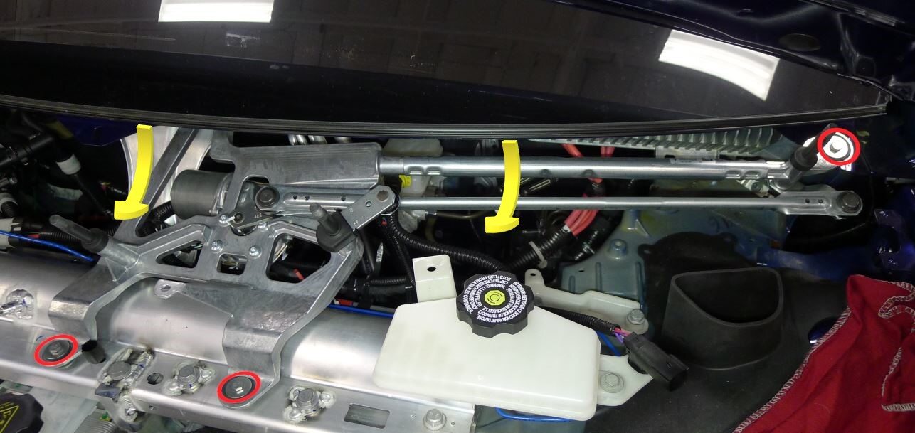
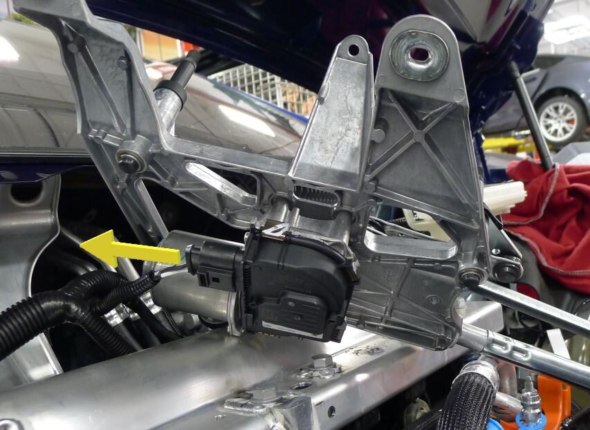
Remove wiper module
注3x bolts, 10mm, 9 Nm, 1x connector, Rotate module forward and up to access connector
-
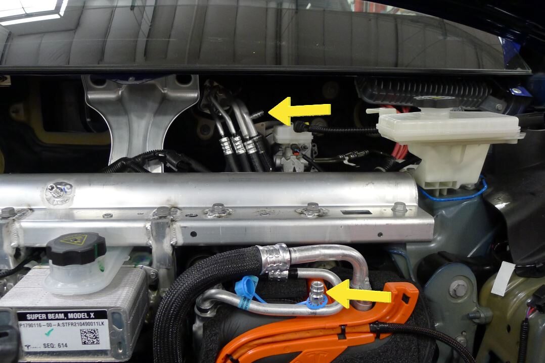
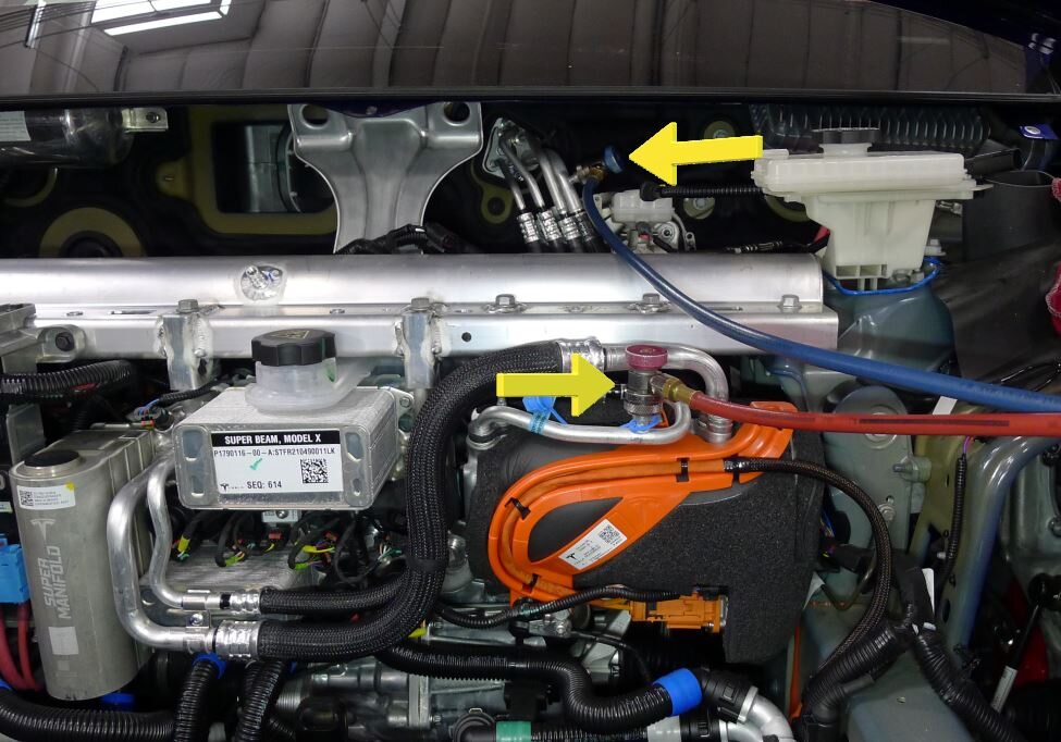
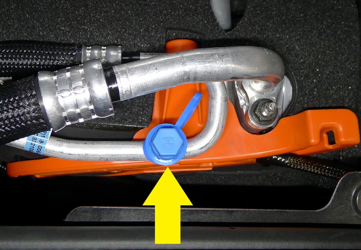
Remove caps from low side and high side AC ports
注2x caps
-
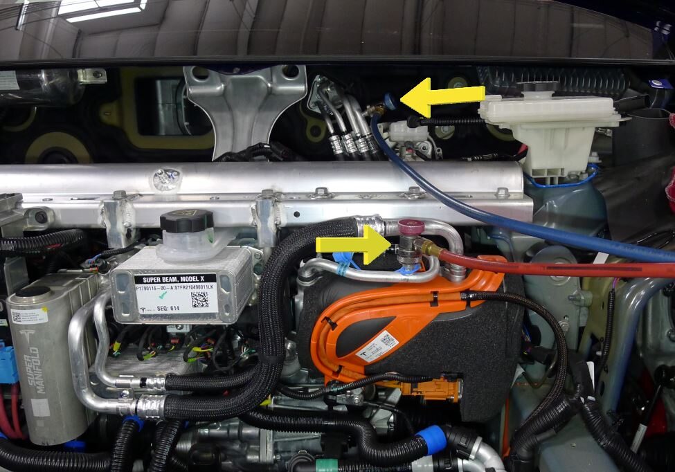
Connect AC hoses to vehicle
-
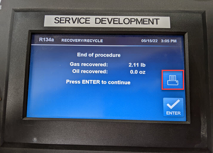
Perform AC recovery
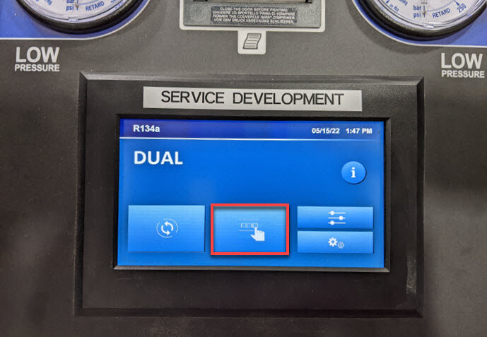
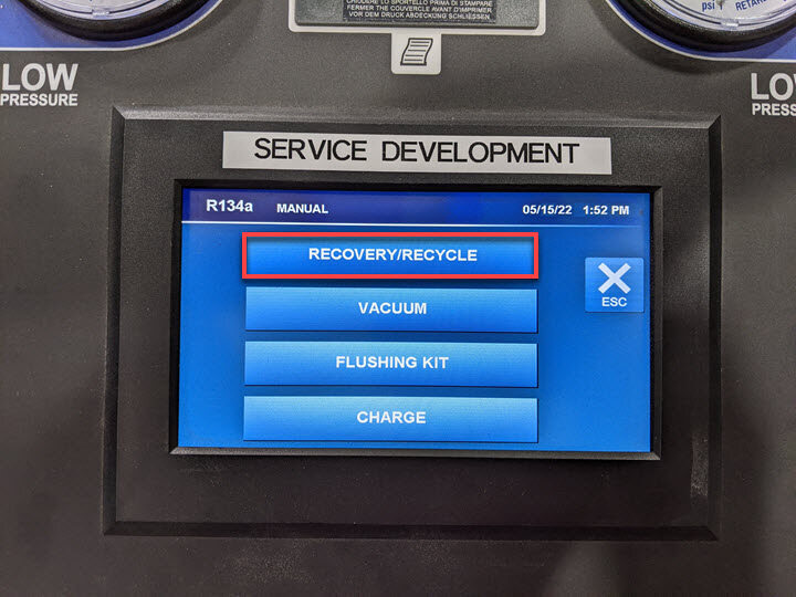
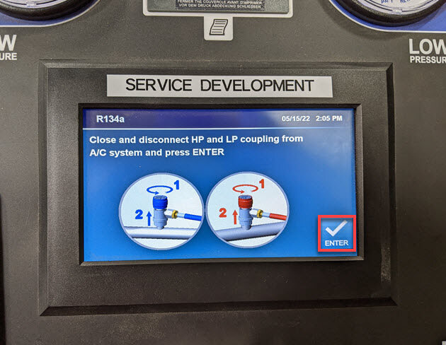
注Touch time only: Note the amount of refrigerant and oil recovered, Manual Menu > Recovery/Recycle > Verify hose connections, Machine will chime once process is complete, Vehicle may be left unattended, Note or print the amount of refrigerant and oil recovered, Refrigerant recovered should be ~2.24 lb (1.02 kg), Oil recovered should be ~0.3 oz (8.87 mL), If drained oil level increased more than 1.01 oz (30 mL) refer to drained oil loss chart https://toolbox.teslamotors.com/articles/353700
-
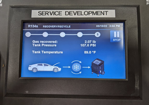
Perform AC recovery
注Run time only: Print results > Screen will automatically go to main menu after print is made
-
Remove AC hoses from vehicle
-
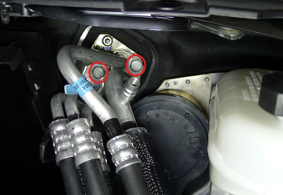
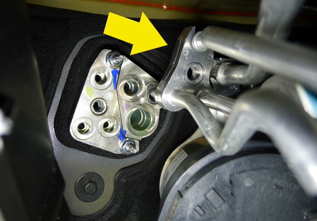
Remove Penta HVAC line from HVAC assembly
注2x bolts, 13mm, 22 Nm
-
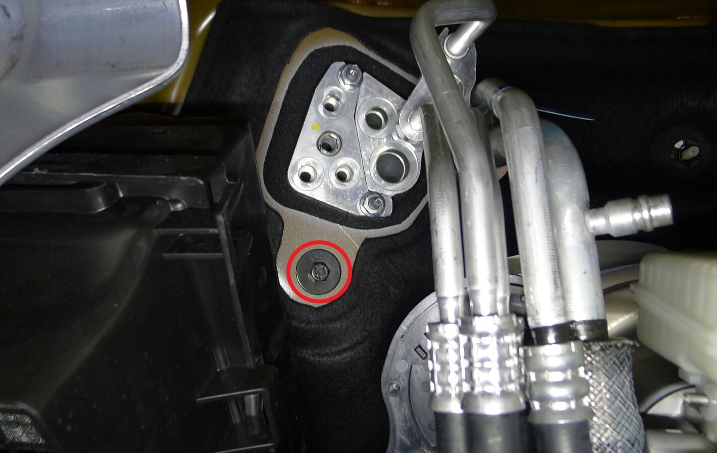
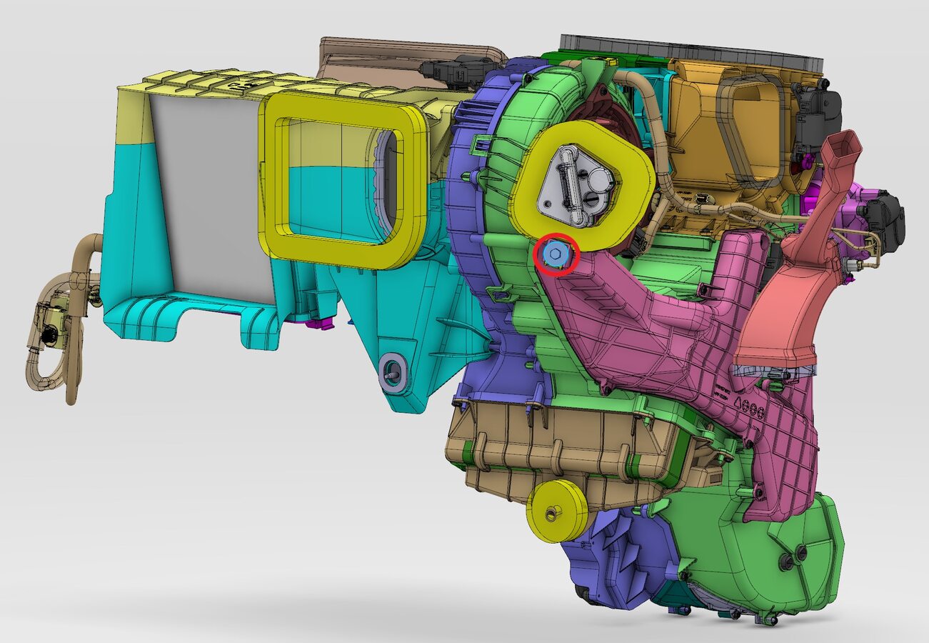
Release HVAC assembly bolt at bulkhead
注1x bolt, 10mm, 8 Nm
-
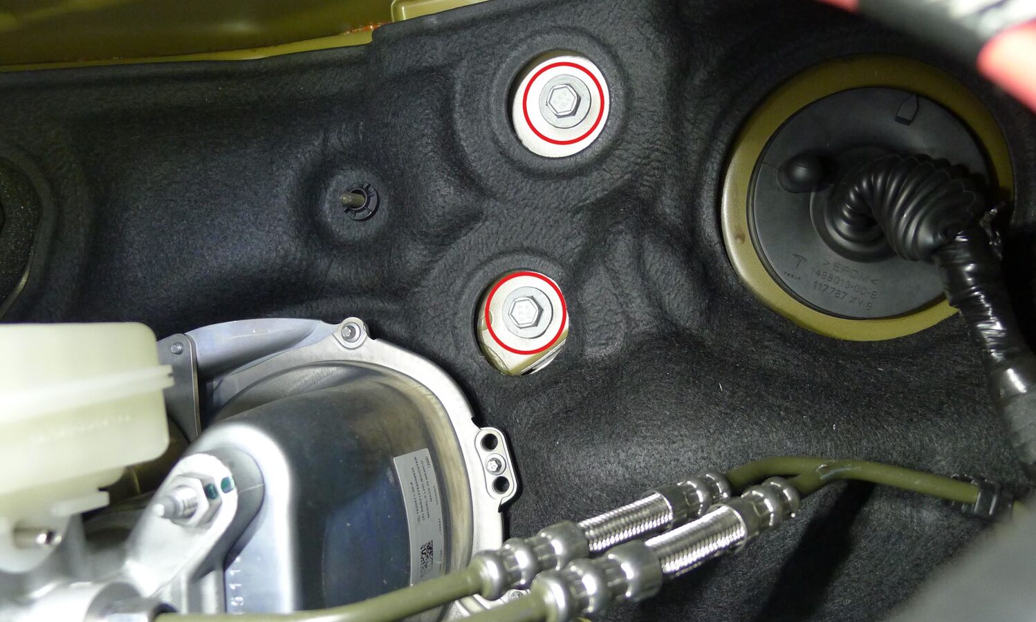
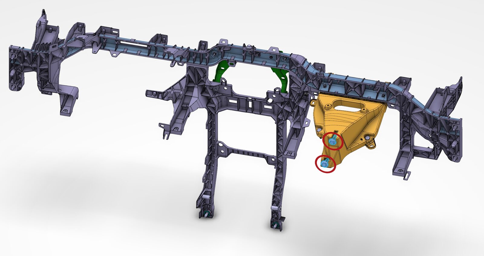
Release upper steering column bracket IP carrier bolts at bulkhead
注2x bolts, 13mm, 27 Nm
-
Remove IP LH mid panel
注6x tabs
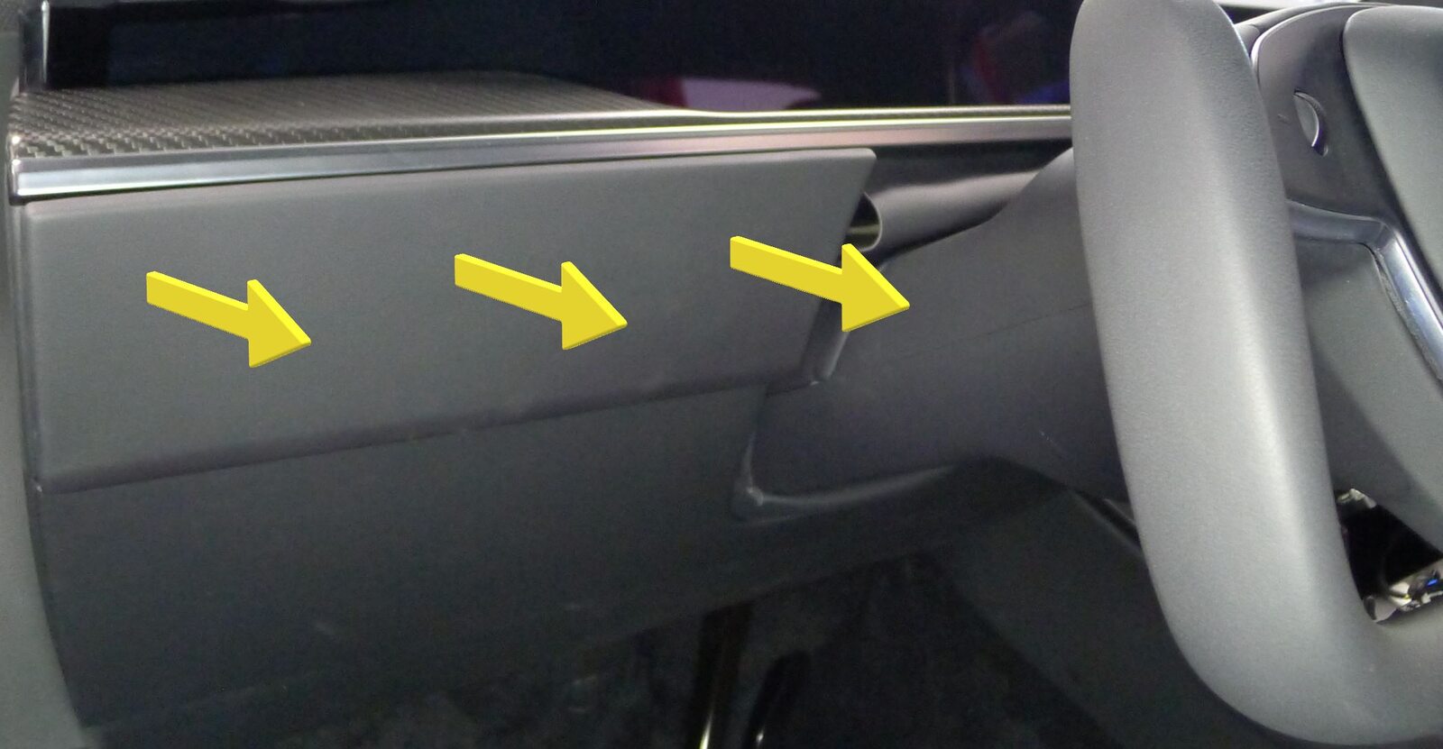
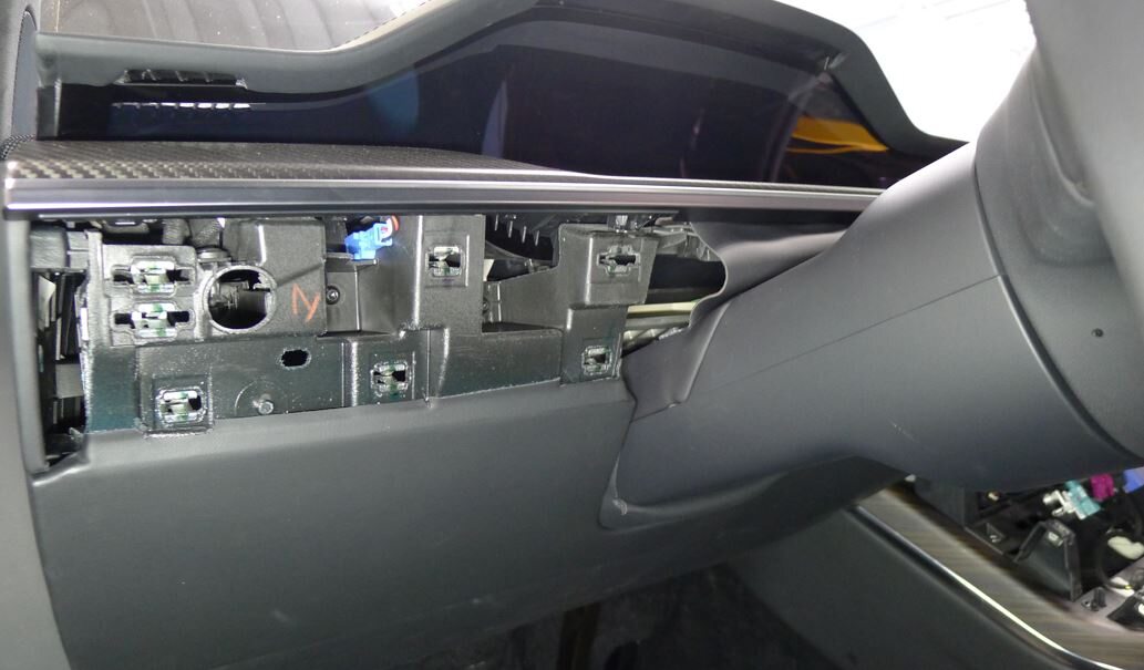
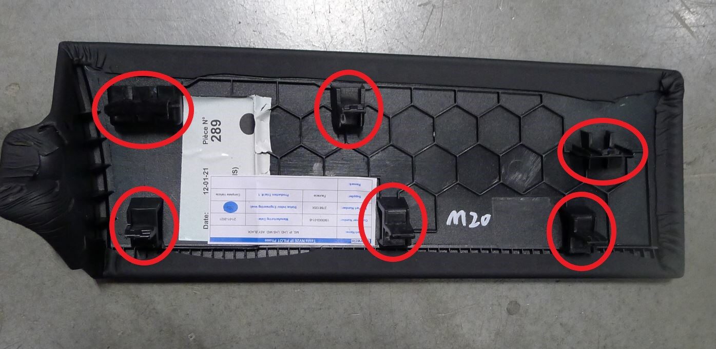
-
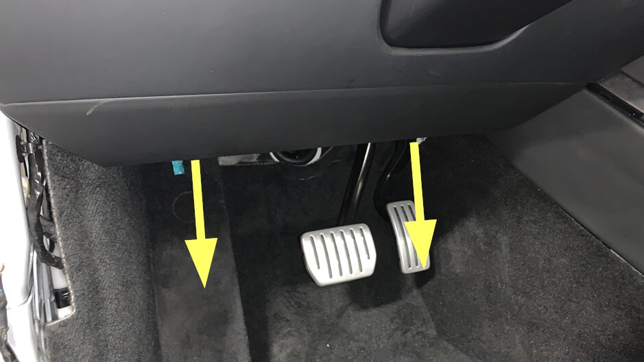
Remove fasteners securing LH knee air bag assembly to vehicle
注2x patch bolts, E10, 8 Nm, Discard after removal
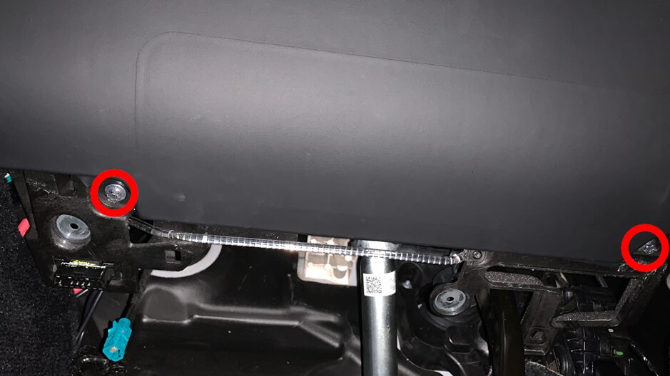
-
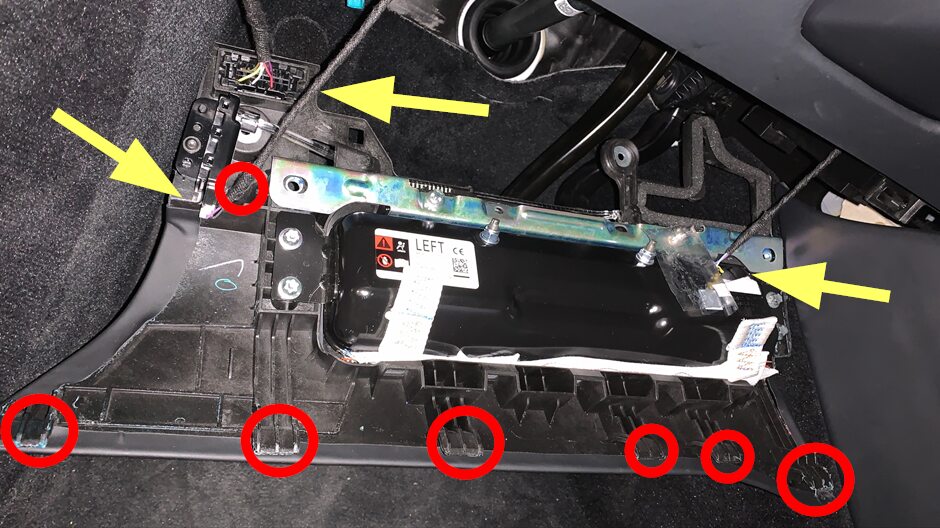
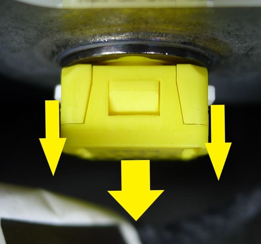
Remove the LH knee air bag assembly from vehicle
注3x connectors, 1x clip, 6x tabs, Release 2x locking tab on airbag connector
-
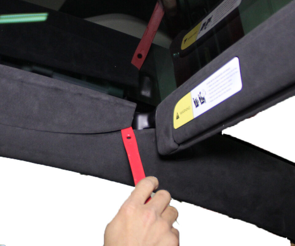
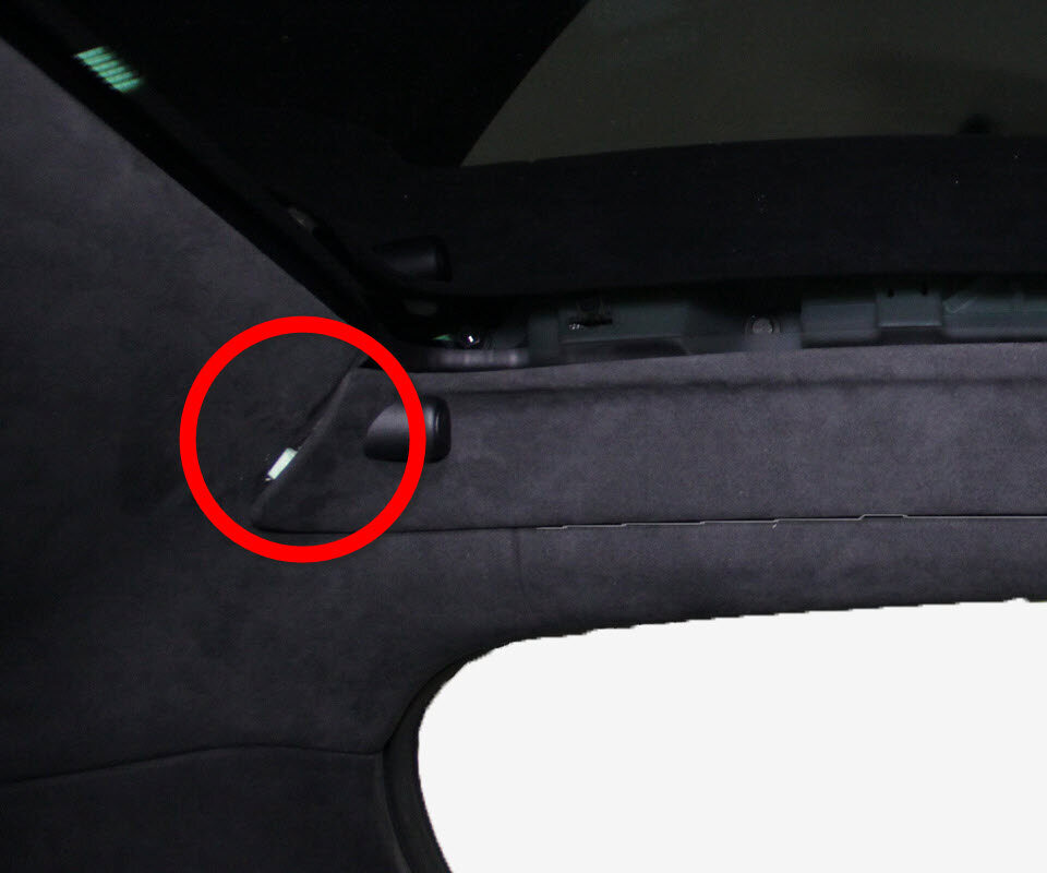
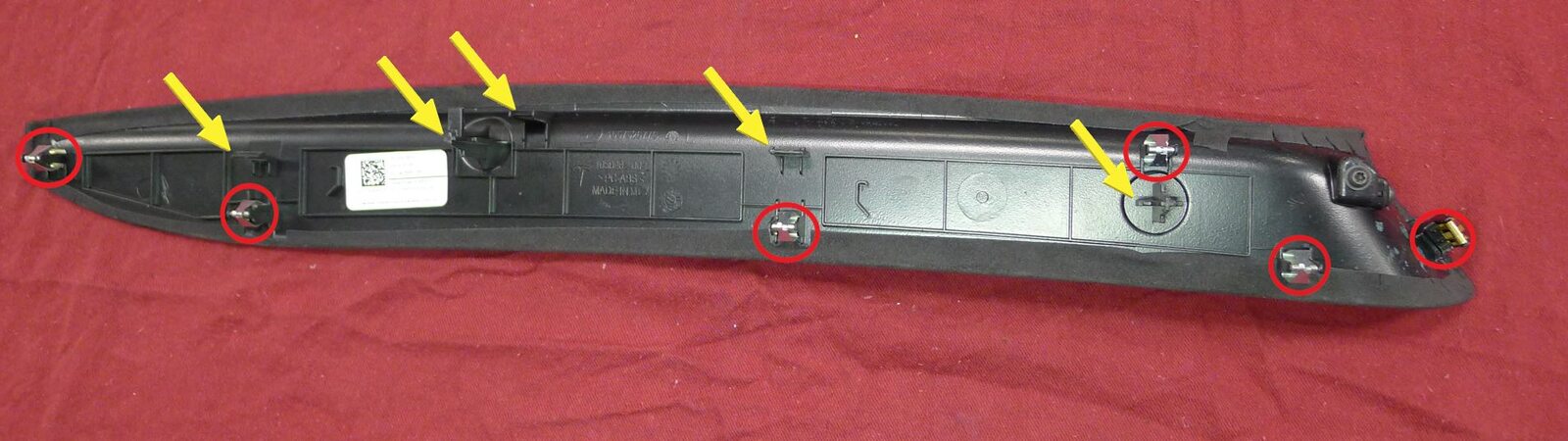
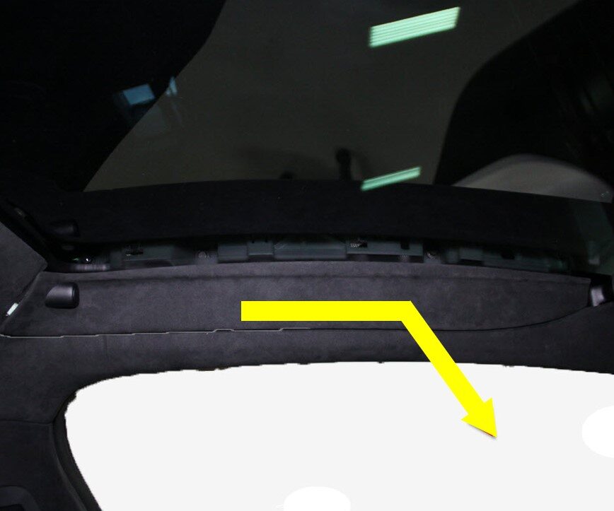
Remove LH sun visor bezel
注6x clips, 5x tabs, Release clips, then slide bezel towards front of vehicle to release
-
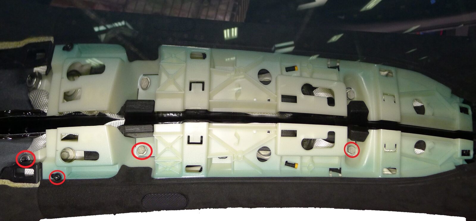
Release LH upper A-pillar from body
注2x bolts, 10mm, 5 Nm, 1x screw, T20, 2.5 Nm, 1x nyloc nut, 13mm, 5 Nm, Discard nut after removal
-
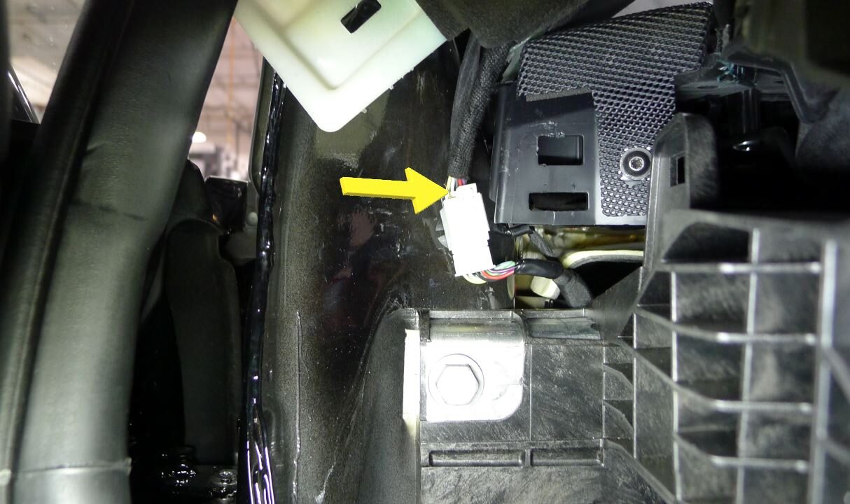
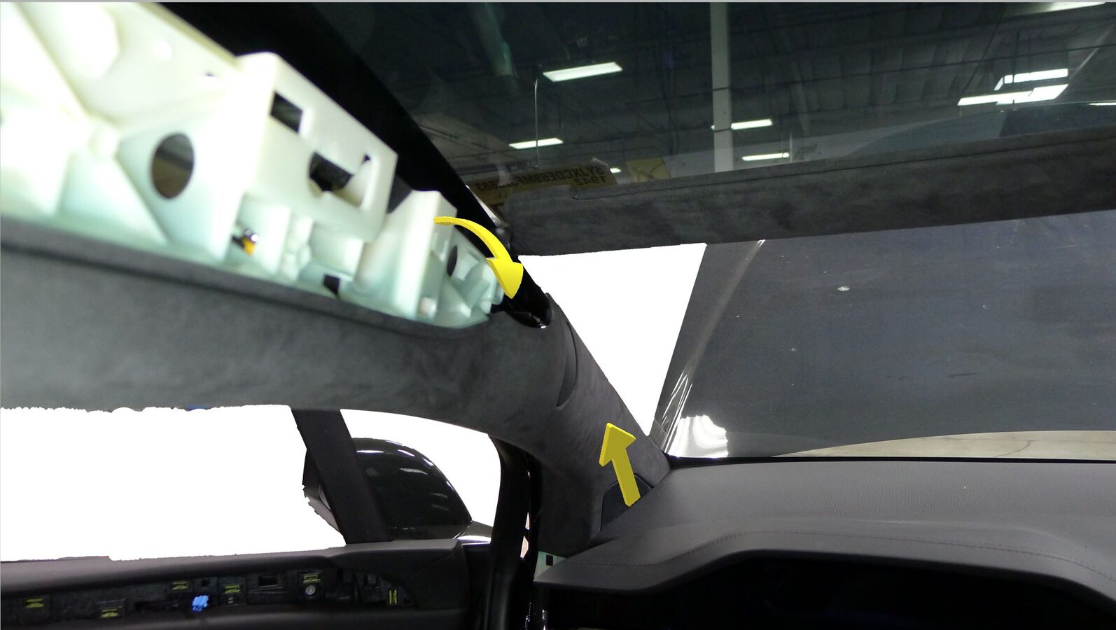
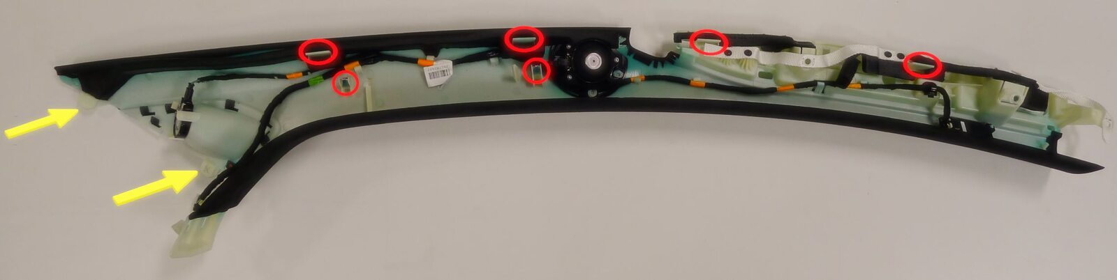
Remove LH upper A-pillar from vehicle
注1x connector, 2x datums, 6x clips, Release clips and rotate pillar inboard to access connector, Release datums upward out of IP sub assembly
-
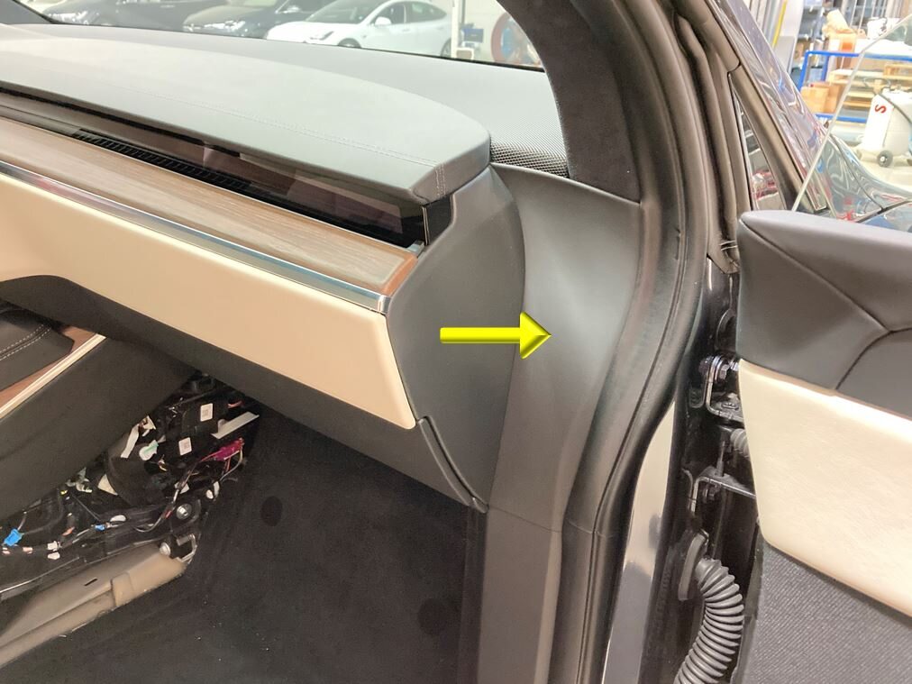
Remove RH IP end cap
注3x clips
-
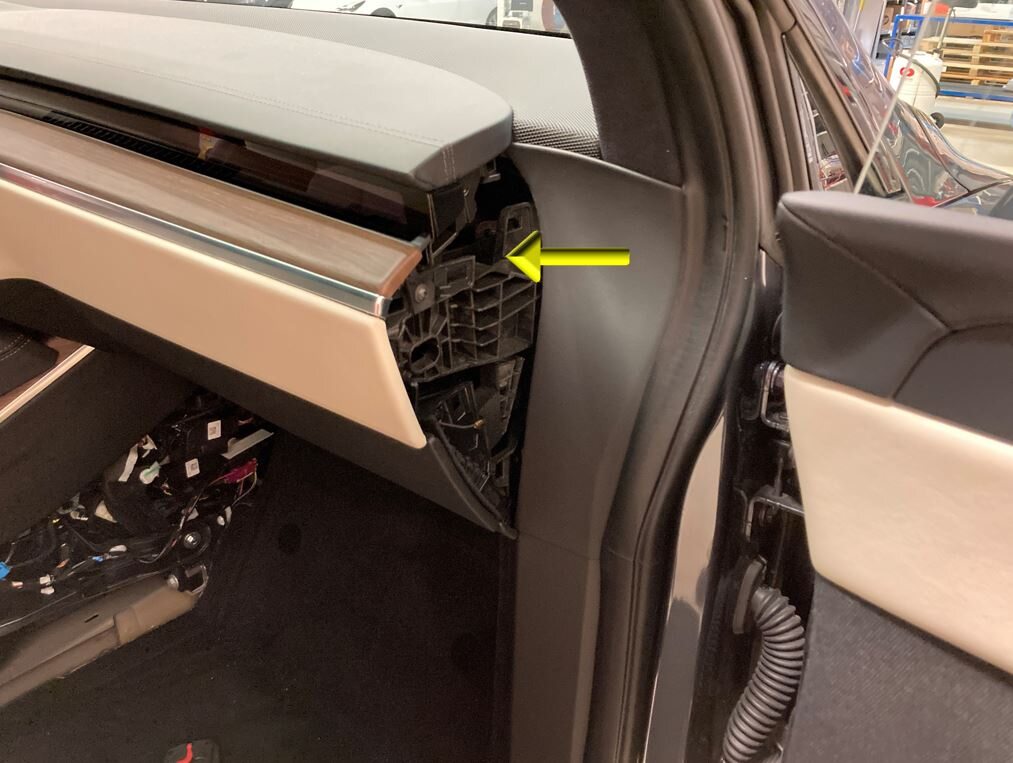
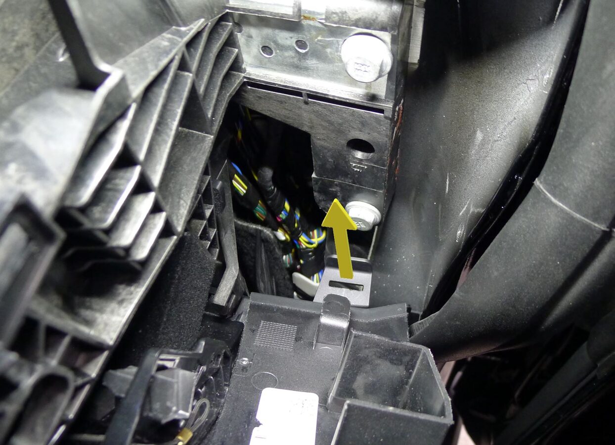
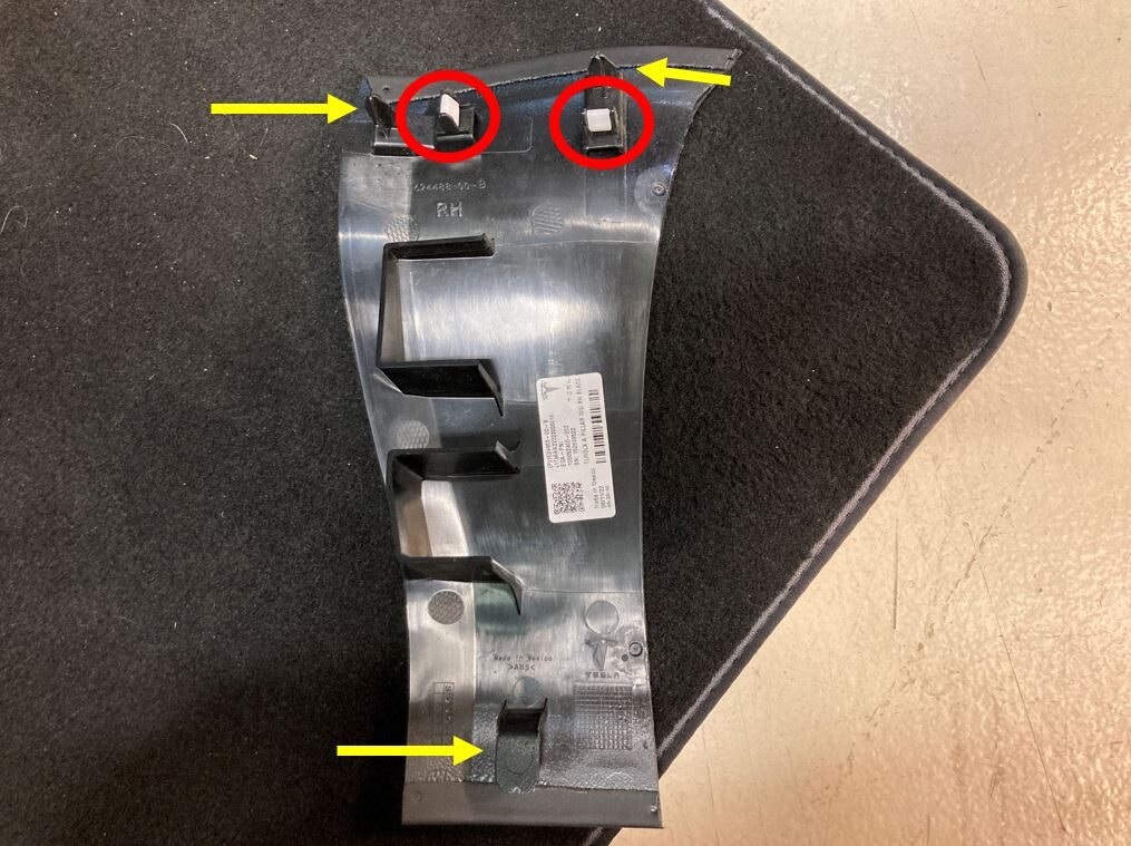
Remove RH mid A-pillar trim
注2x clips, 3x datums, Release clips from upper A-pillar and IP sub assembly, Lift mid A-pillar trim out of lower A-pillar trim
-
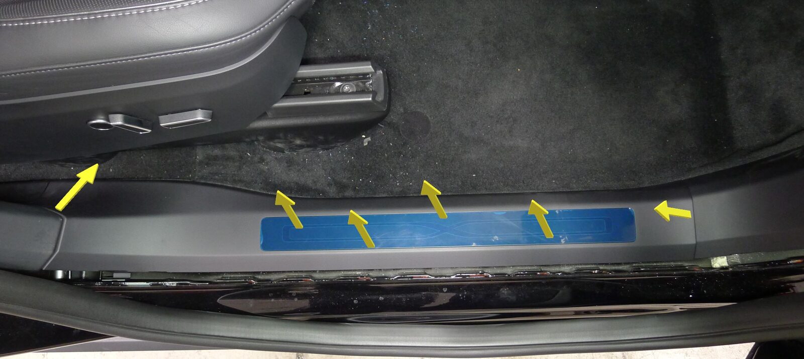
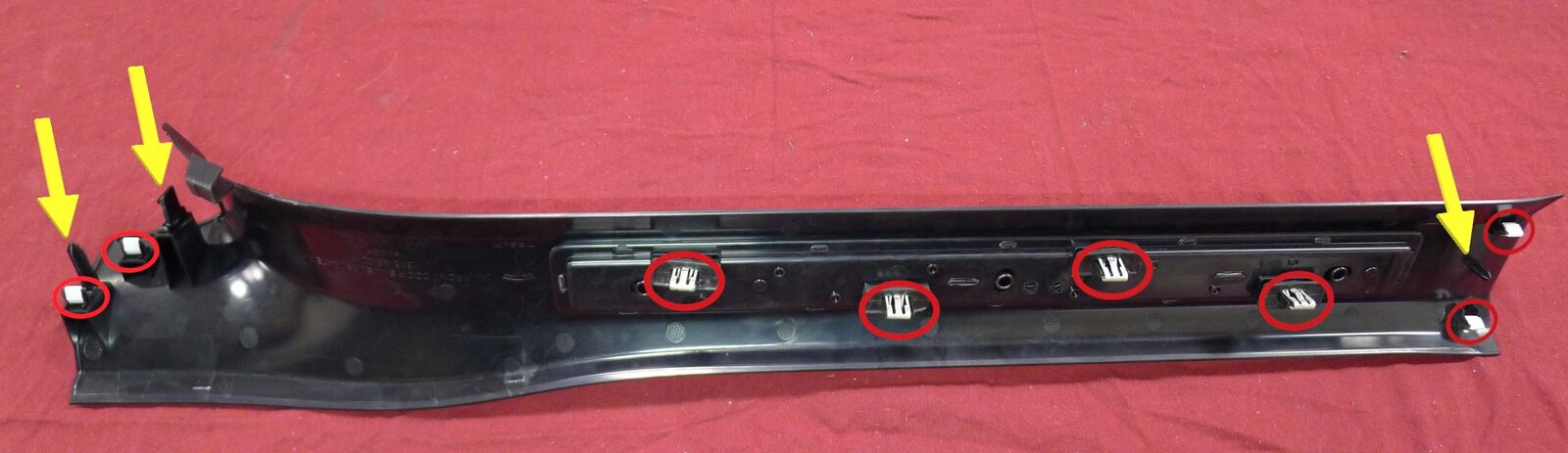
Remove RH front door sill trim panel
注8x clips, 3x datums
-
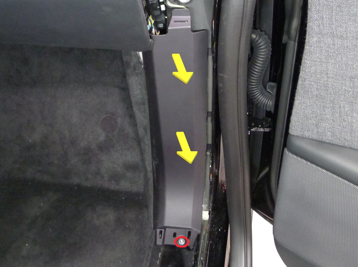
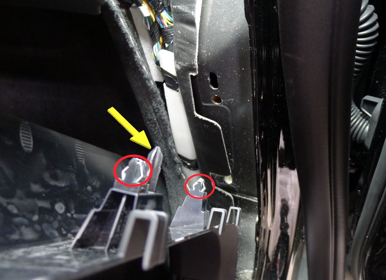
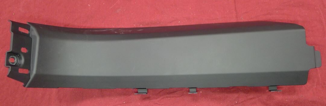
Remove RH lower A-pillar trim
注1x bolt, T25, 5 Nm, 2x clips, 1x datum
-
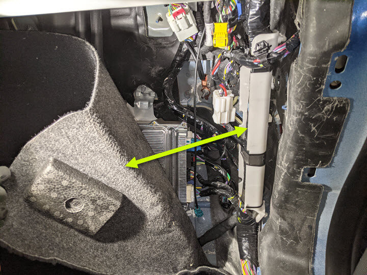
Fold RH front cabin carpet aside for access
-
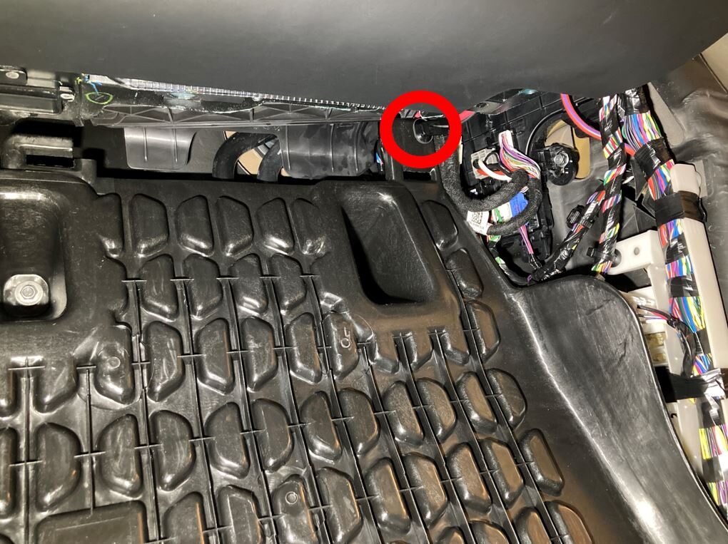
Release harness from RH footrest panel
注1x clip
-
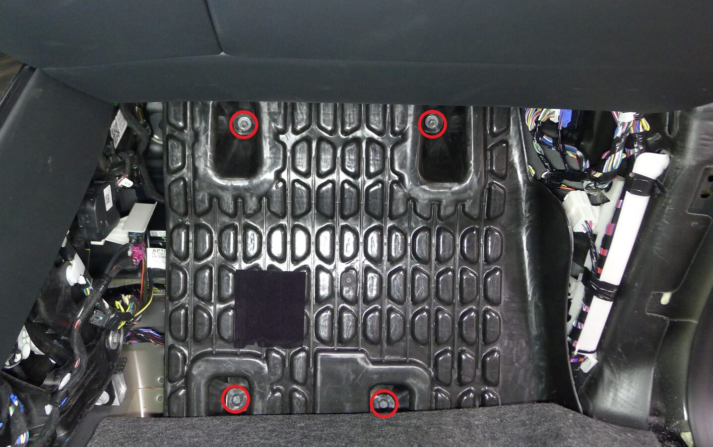
Release RH footrest panel
注2x bolts, 10mm, 5 Nm, 2x nut, 10mm, 5 Nm
-
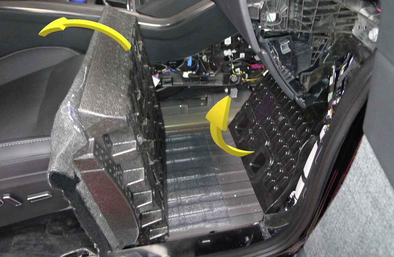
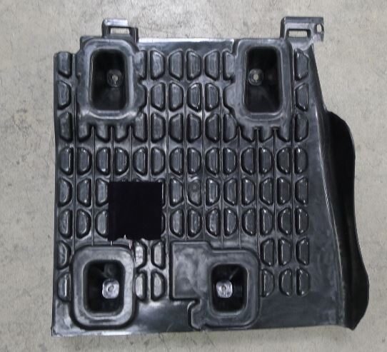
Remove RH footrest panel
注Fold RH primary support carpet up, Rotate RH footrest panel out of vehicle
-
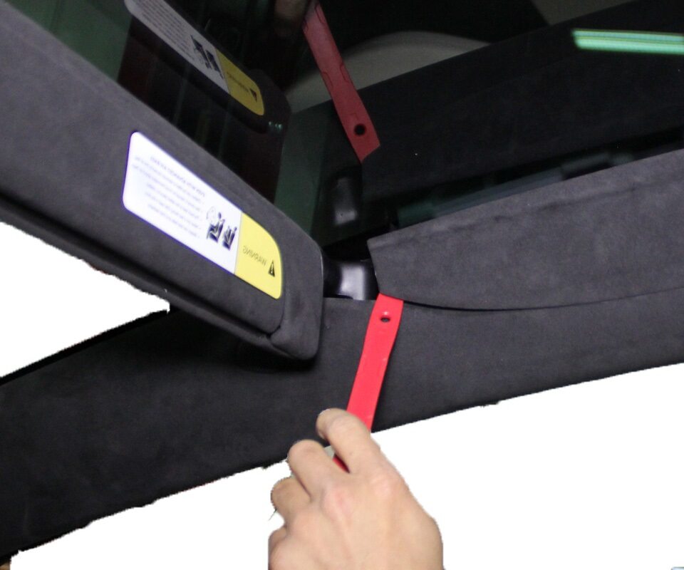
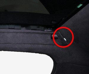
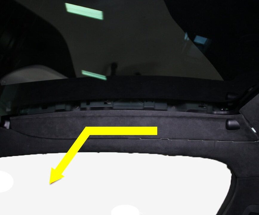
Remove RH sun visor bezel
注6x clips, 1x tab, Release clips, then slide bezel towards front of vehicle to release
-
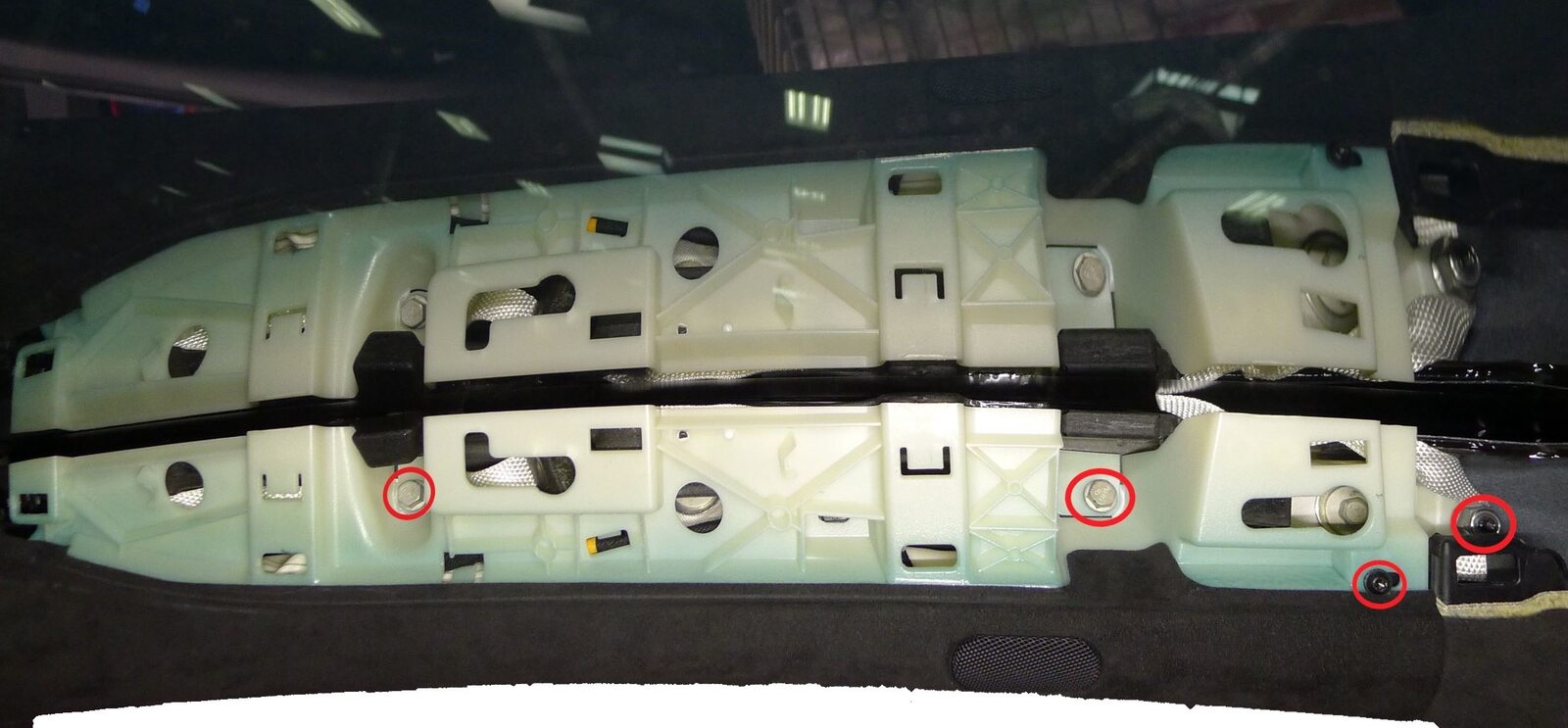
Release RH upper A-pillar from body
注2x bolts, 10mm, 5 Nm, 1x screw, T20, 2.5 Nm, 1x nyloc nut, 13mm, 5 Nm, Discard nut after removal
-
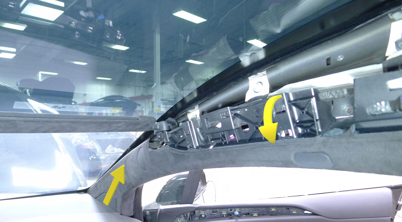
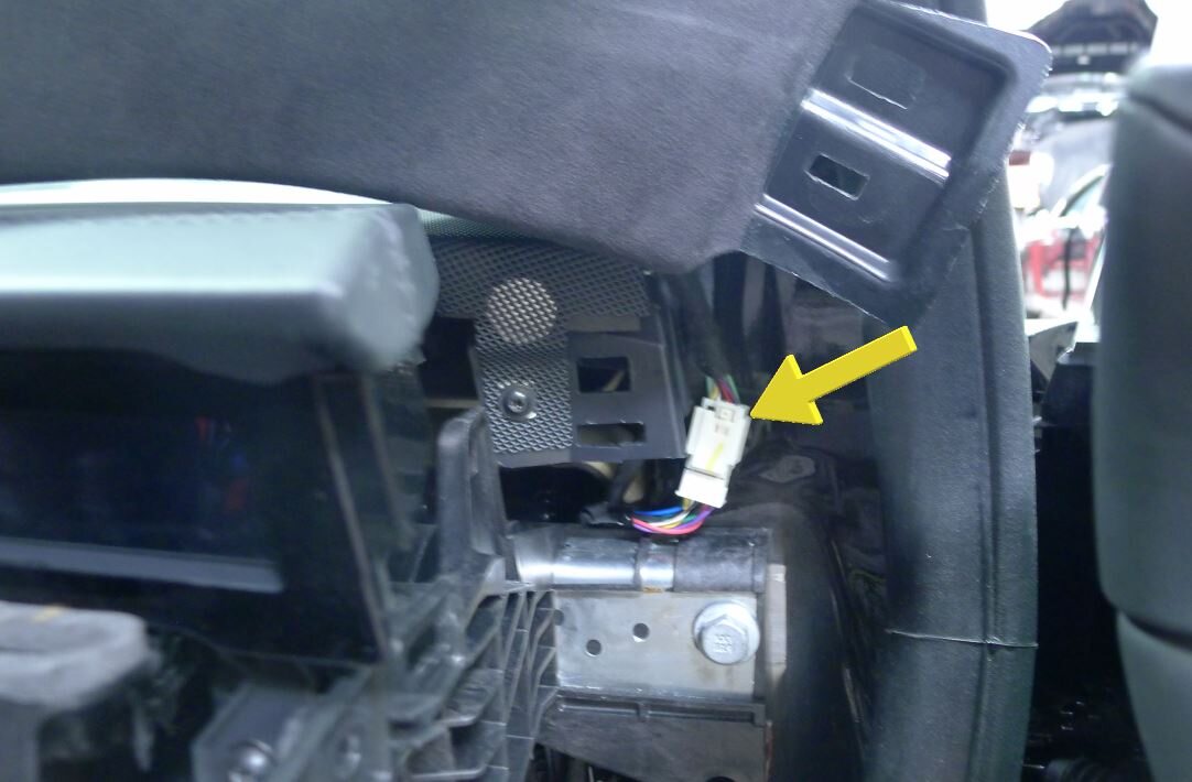
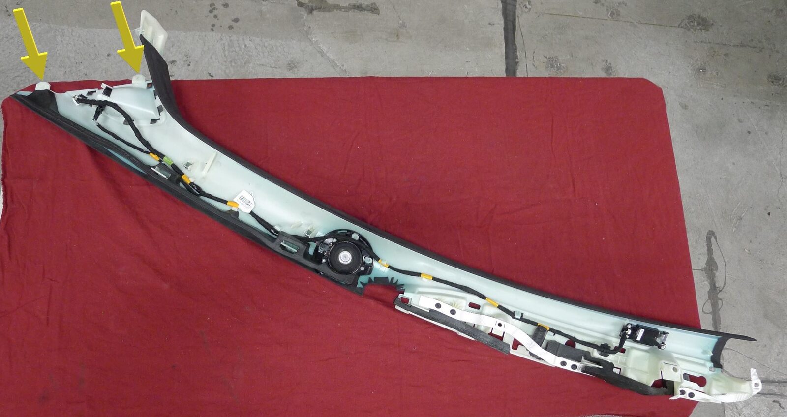
Remove RH upper A-pillar from vehicle
注1x connector, 2x datums, Rotate pillar inboard to access connector, Release datums upward out of IP sub assembly
-
Release the IP service panel.
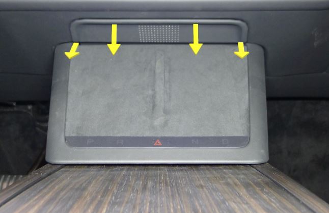
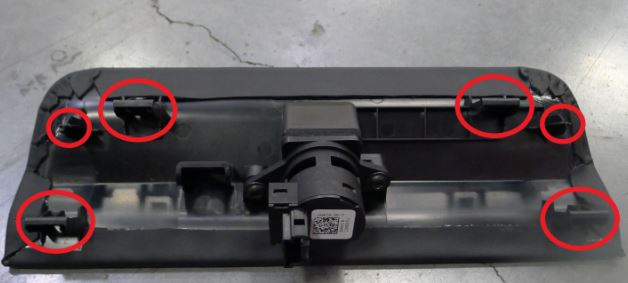
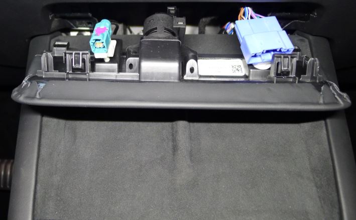
-
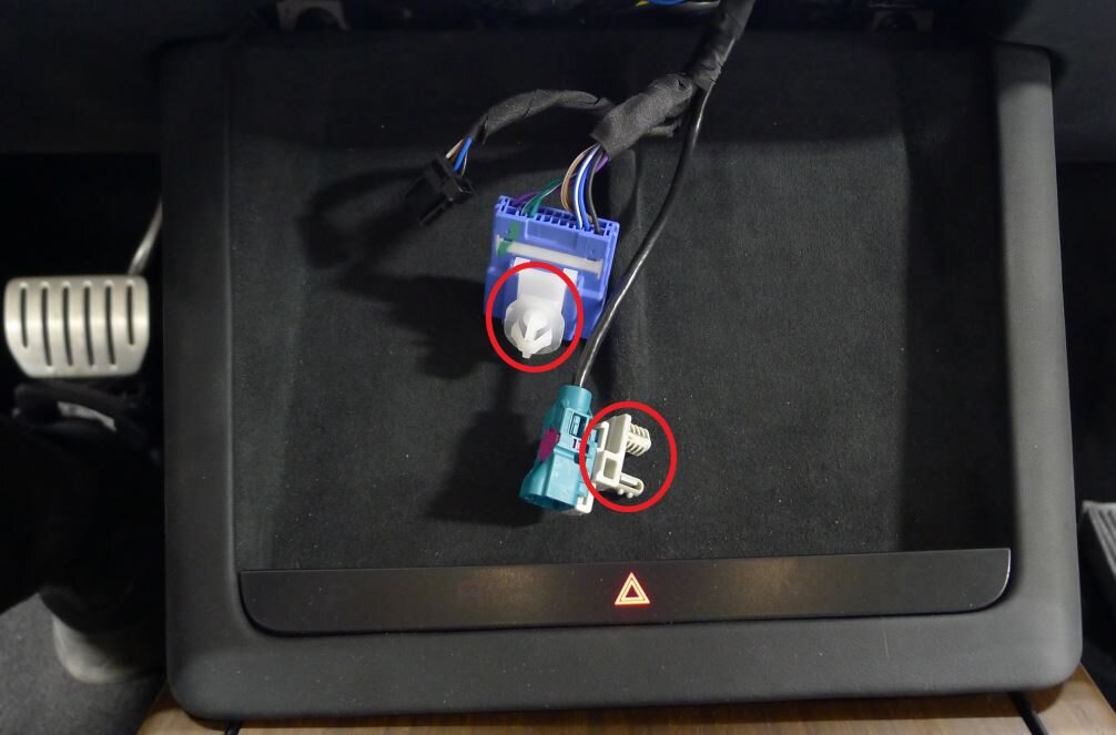
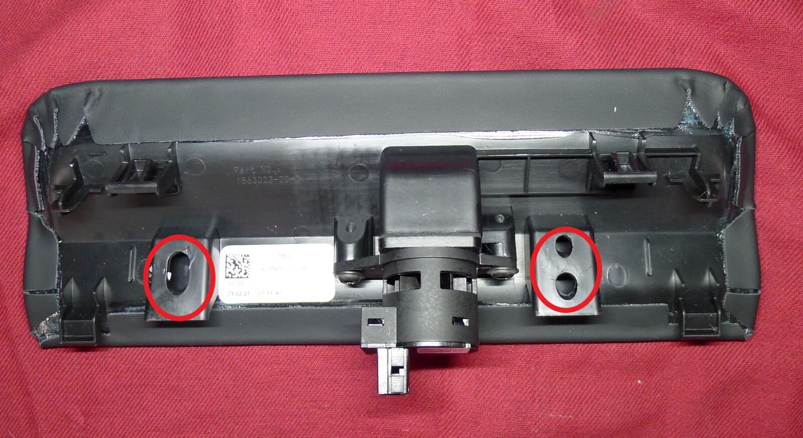
Release diagnostic and CAN harnesses from IP service panel
注2x clips
-
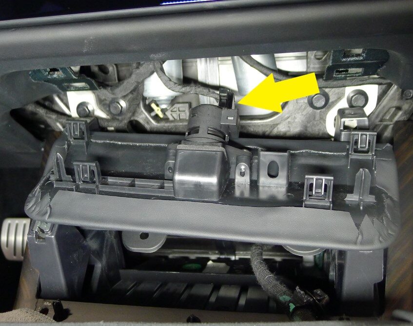
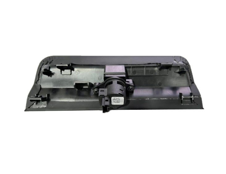
Remove IP service panel
注1x connector
-
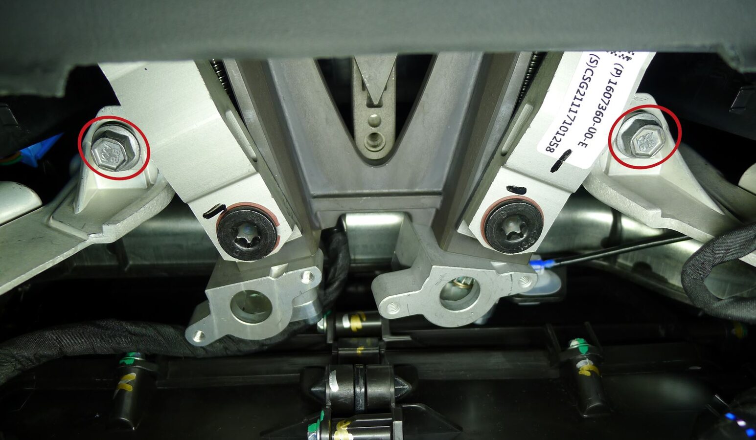
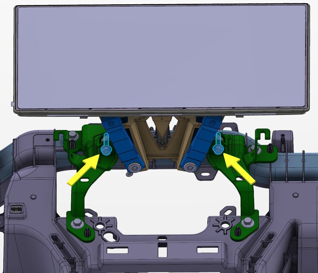
Remove center display bracket bolts
注2x bolts, 10mm, 11.5 Nm
-
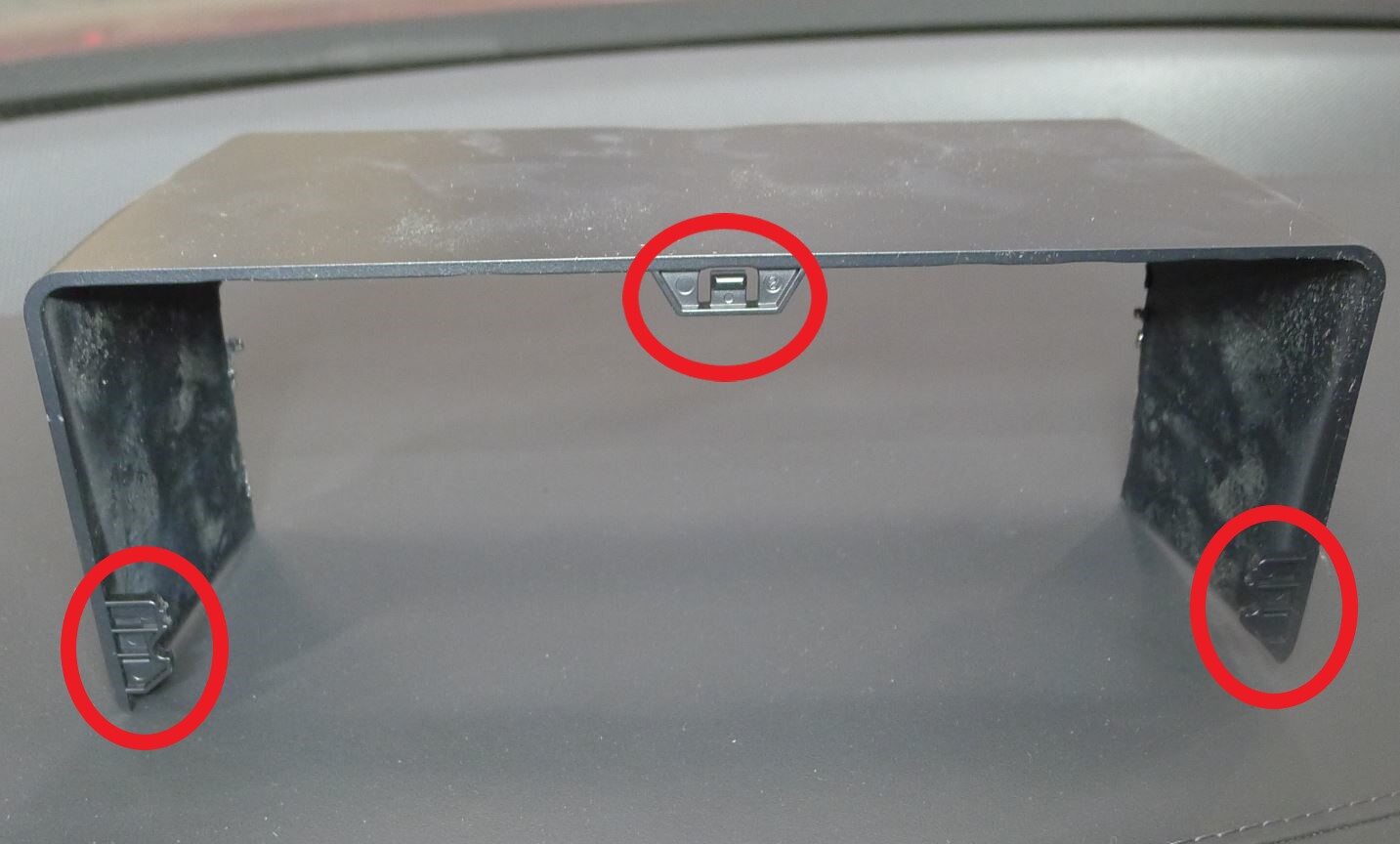
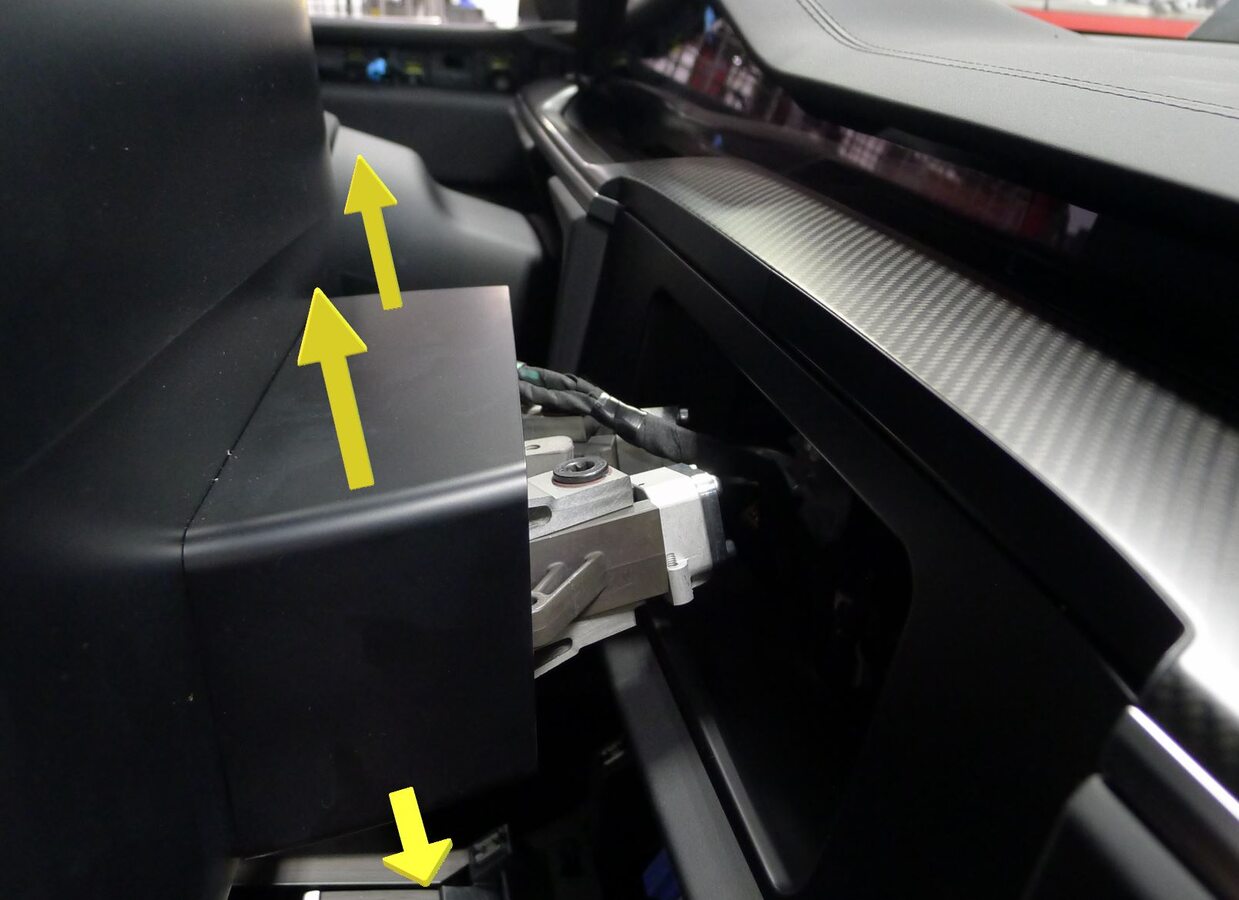
Remove center display shroud
注3x tabs, Slide display outwards until shroud fully clears IP and support, Release the bottom tabs and pull upward
-
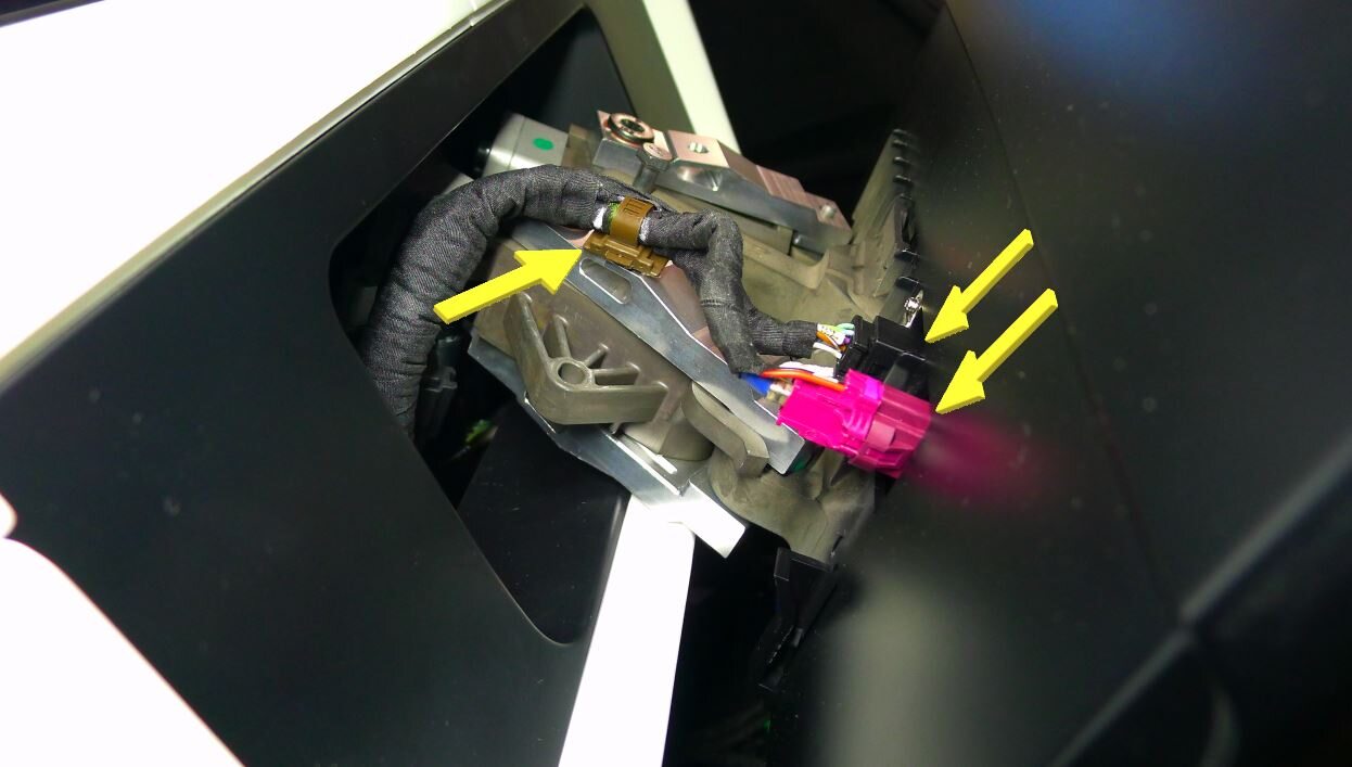
Release center display coax and power connectors
注2x connectors, 1x clip, Slide display rearward outwards from IP bracket and support during connector release
-
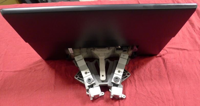
Remove center display
注Slide rearward, Place on soft clean surface
-
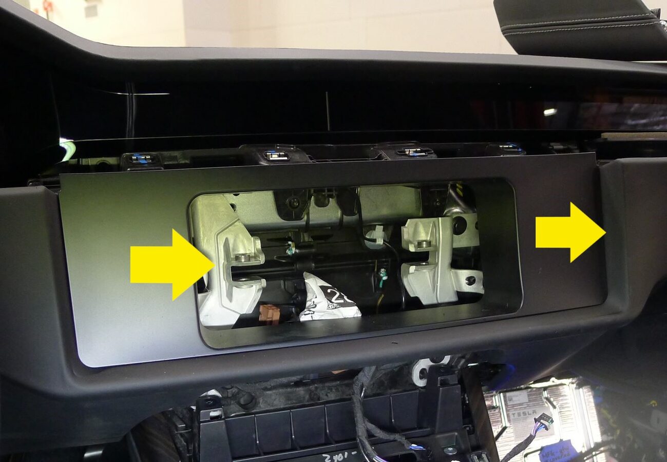
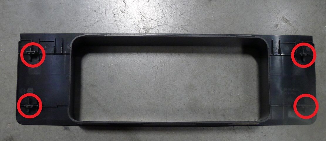
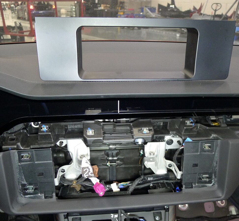
Remove IP closeout panel
注4x tabs
-
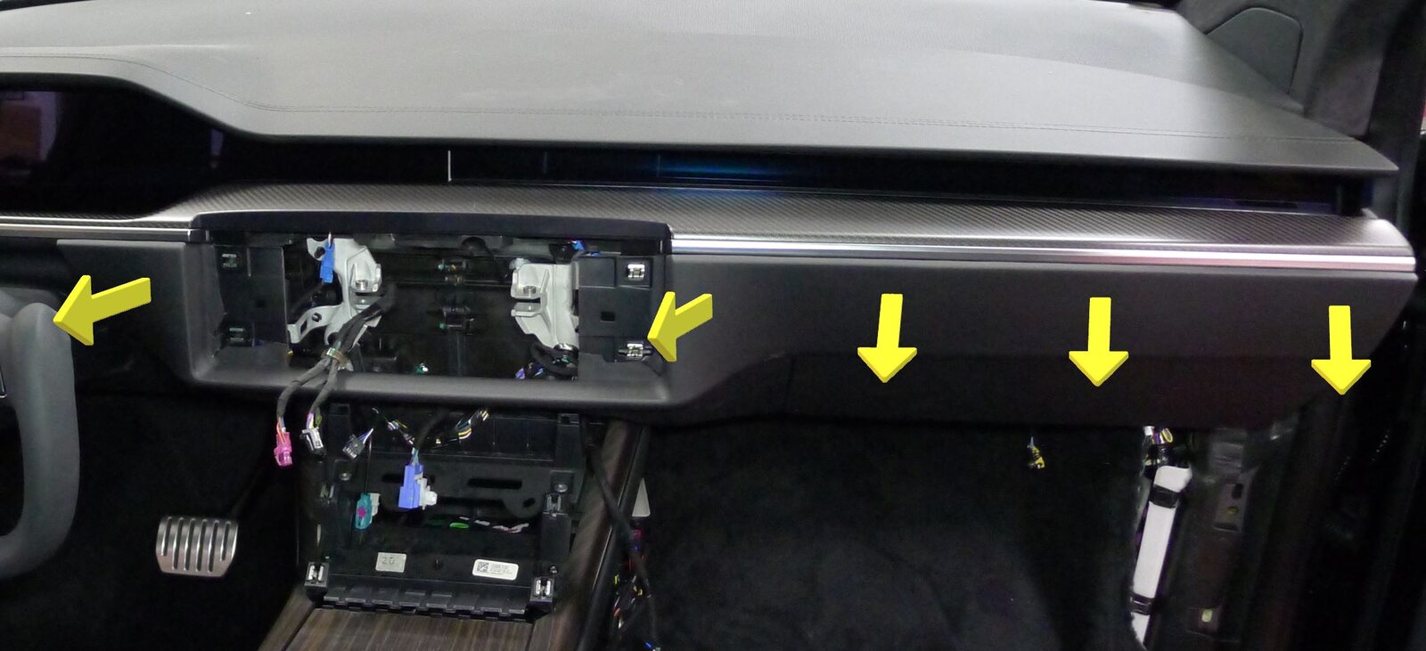
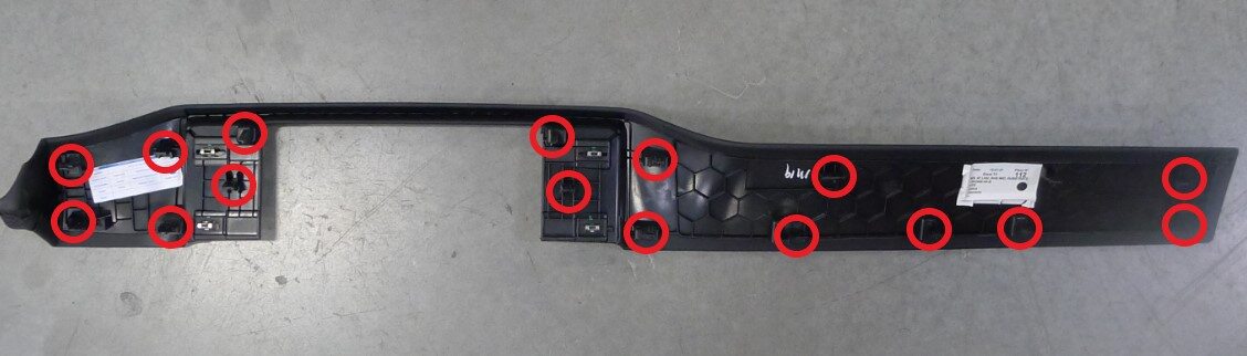
Remove IP RH mid Panel
注14x tabs, 2 datums
-
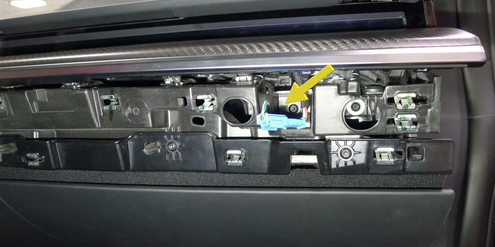
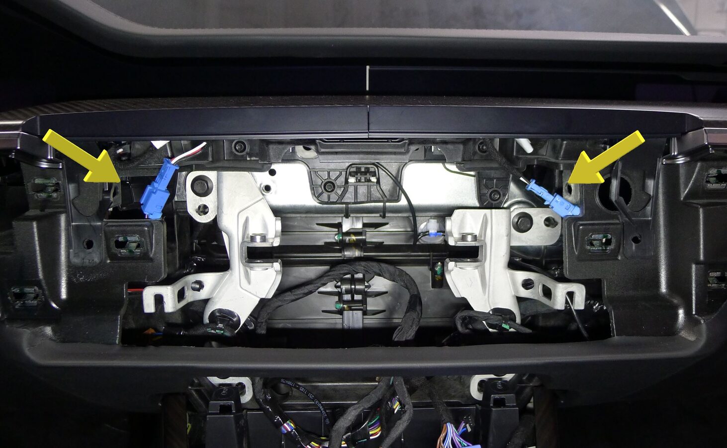
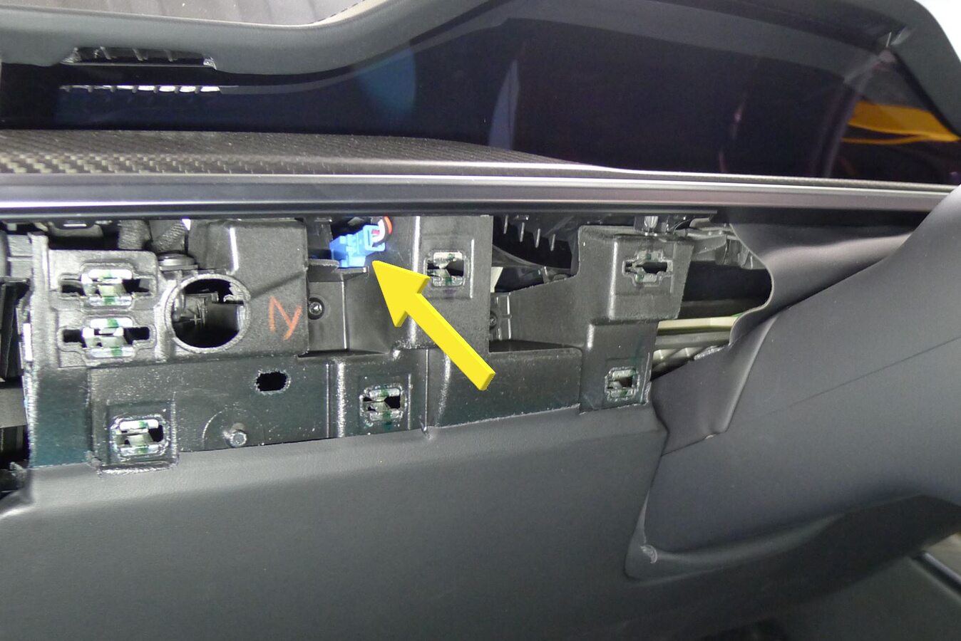
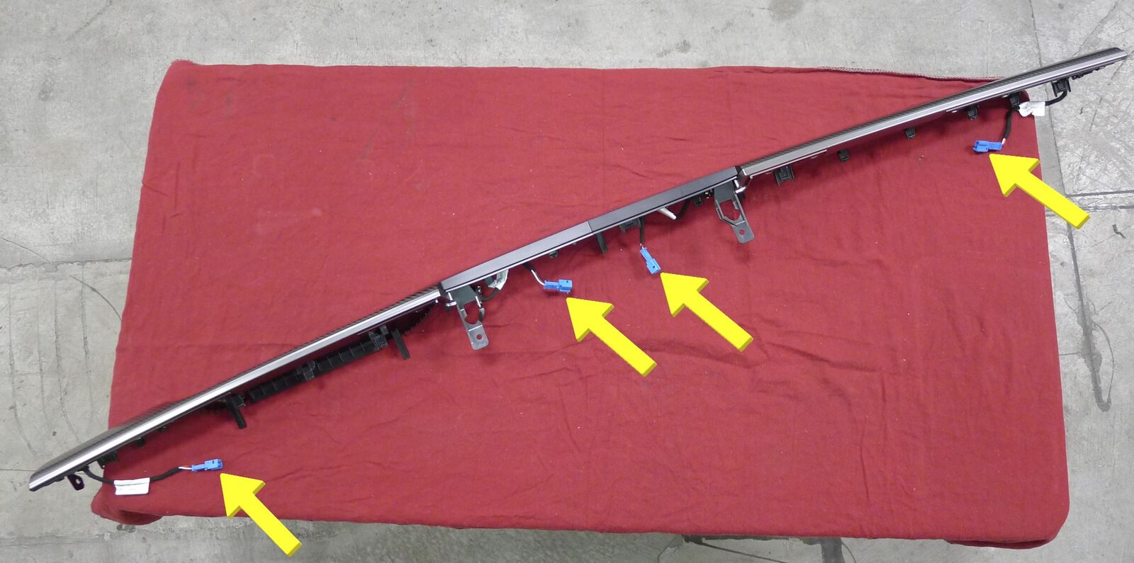
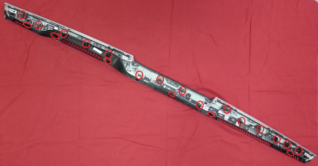
Remove IP Decor
注21x clips, 6x datums, 4x connectors, Release each IP decor connector clip from IP carrier then disconnect from IP harness
-
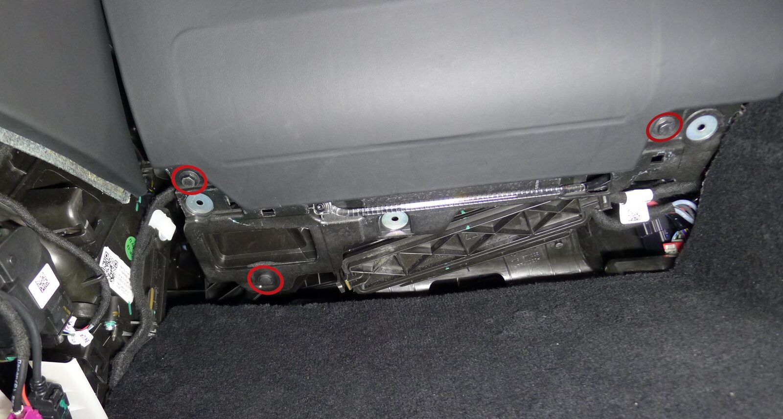
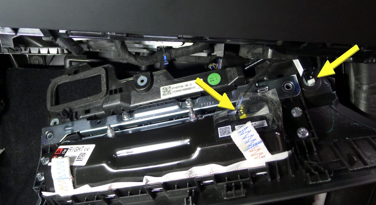
Remove fasteners securing RH knee air bag assembly to vehicle
注2x bolts, 10mm, 8 Nm, 1x clip
-
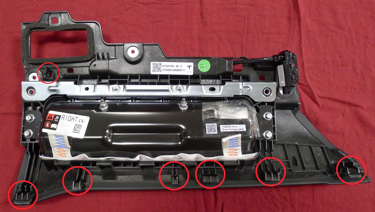
Remove the RH knee air bag assembly from vehicle
注2x connectors, 1x clip, 6x tabs, Release 2x locking tab on air bag connector
-
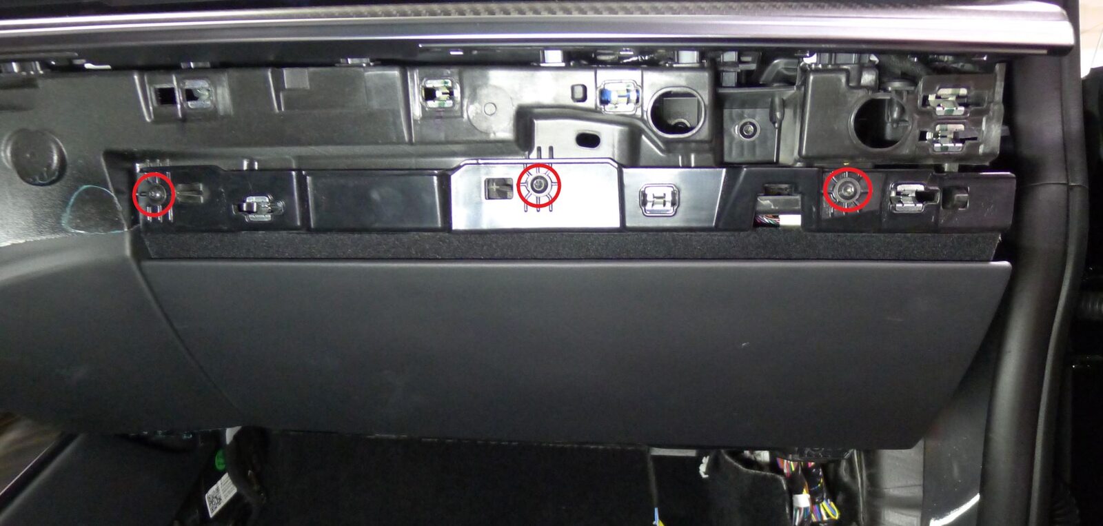
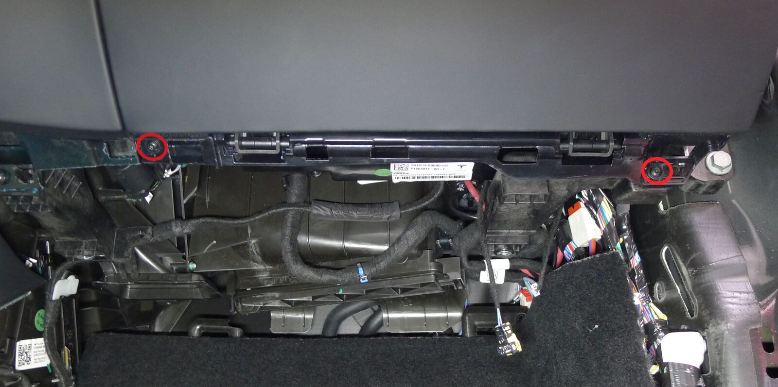
Release glove box
注5x screws, T20, 3 Nm
-
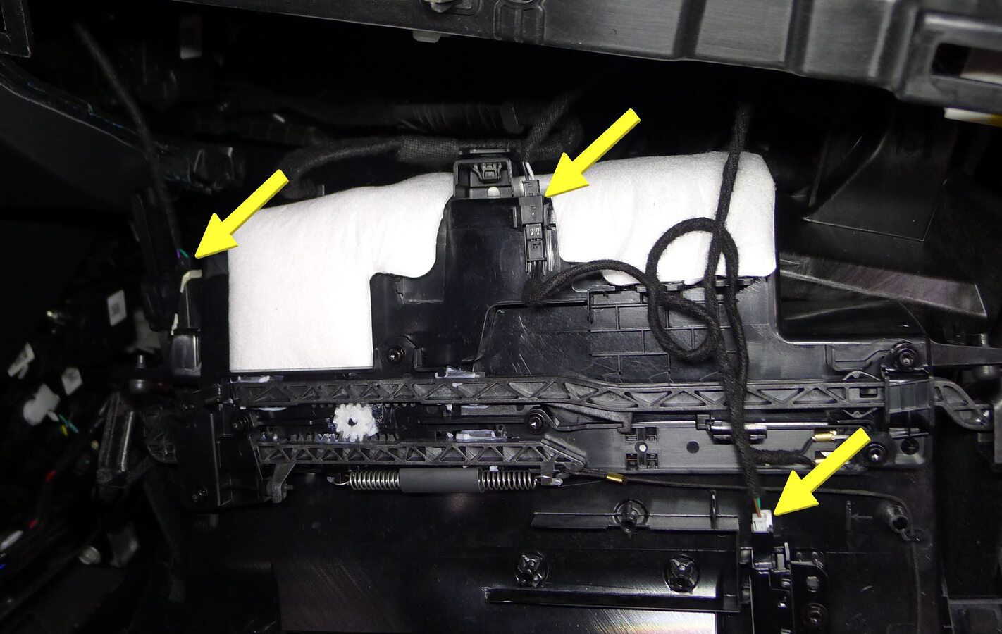
Release glove box connectors
注3x connectors
-
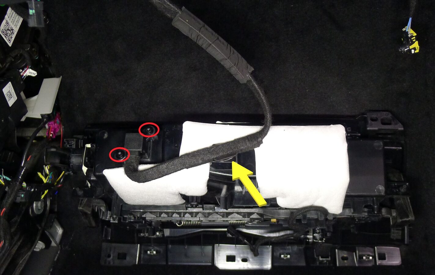
Remove USB outlet
注2x screws, T20, 3 Nm, 1x clip
-
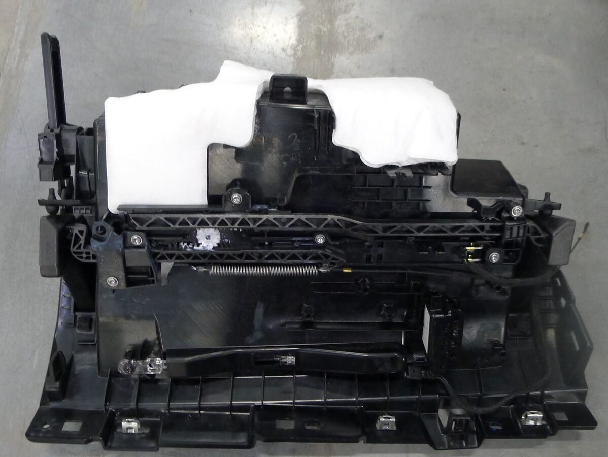
Remove glove box
-
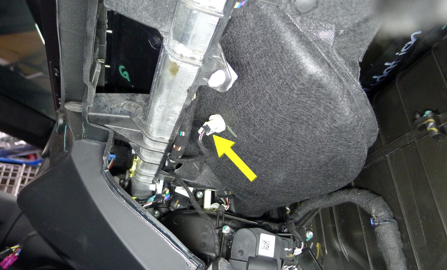
Release passenger IP air duct temperature sensor connector
注1x connector
-
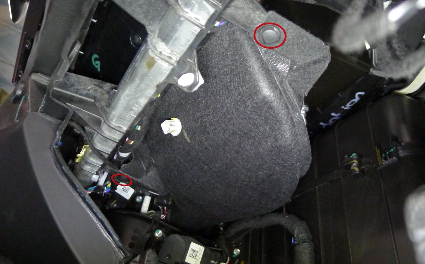
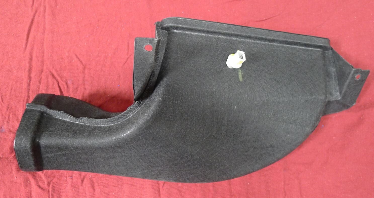
Remove passenger IP air duct
注2x push-pull rivets
-
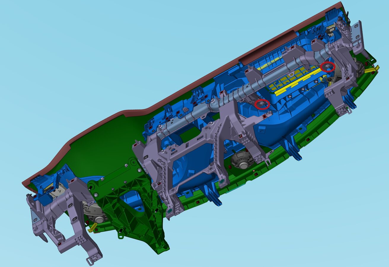
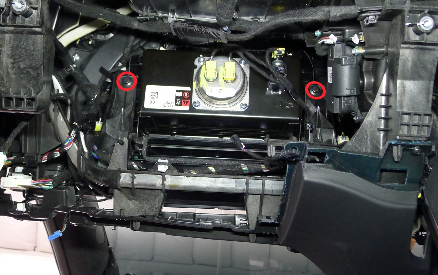
Remove IP carrier cross beam screws
注2x bolts, 10mm, 3 Nm
-
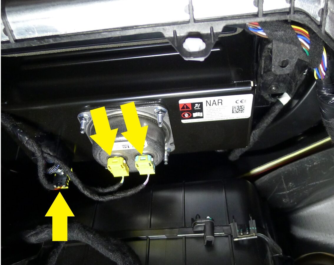
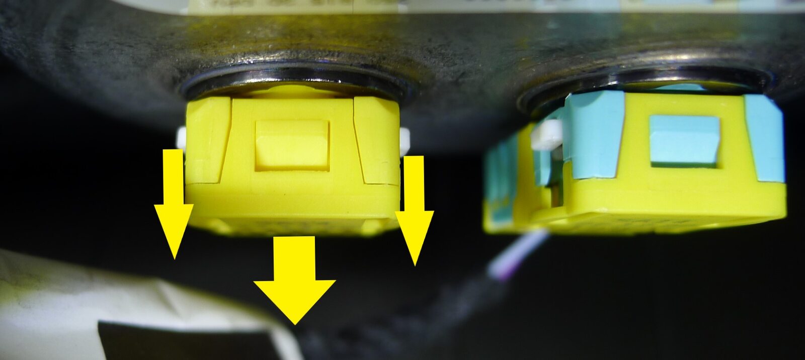
Release passenger IP airbag connectors
注3x connectors, Pull down spring loaded locks simultaneously to release airbag connectors
-
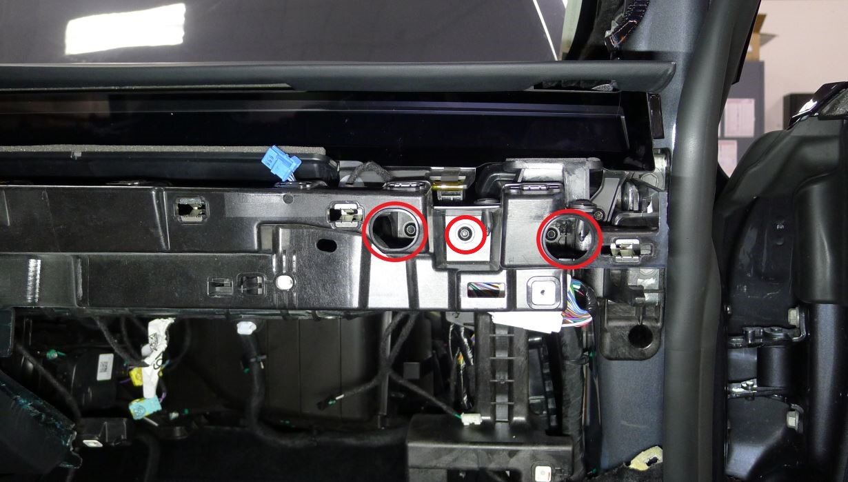
Release RH lower instrument panel
注3x screws, T20, 3 Nm
-
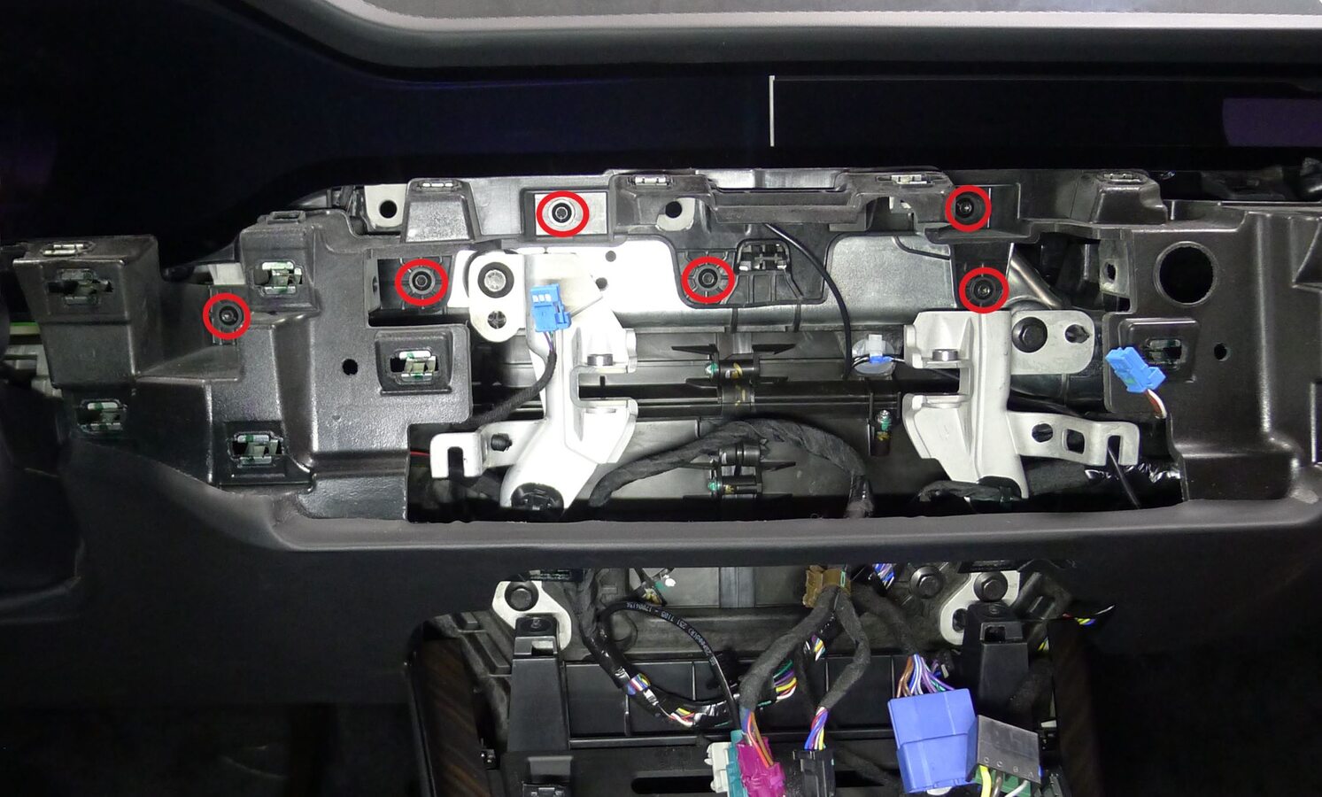
Release center lower instrument panel
注6x screws, T20, 3 Nm
-
Release LH lower instrument panel
注3x screws, T20, 3 Nm
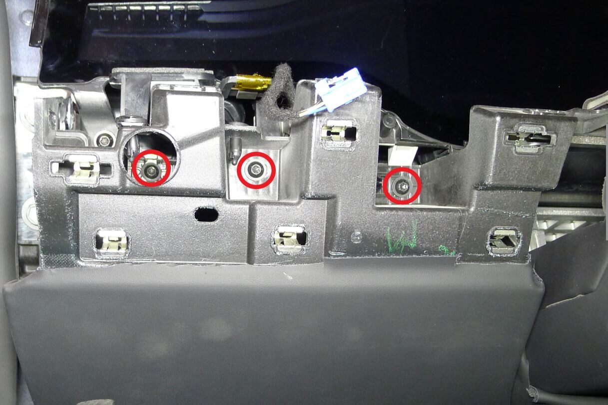
-
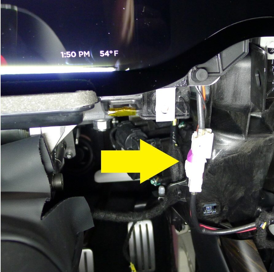
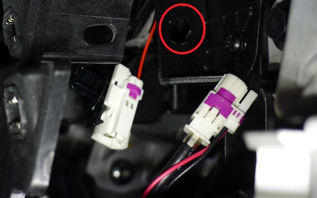
Release instrument cluster harness
注1x connector, 1x clip
-
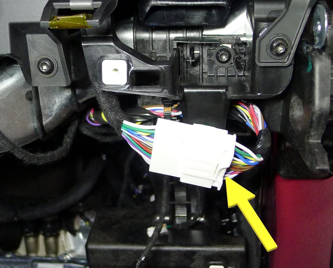
Release IP trim harness
注1x connector, 1x clip
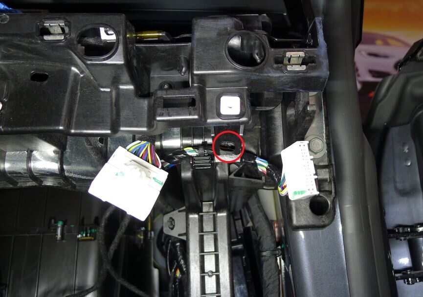
-
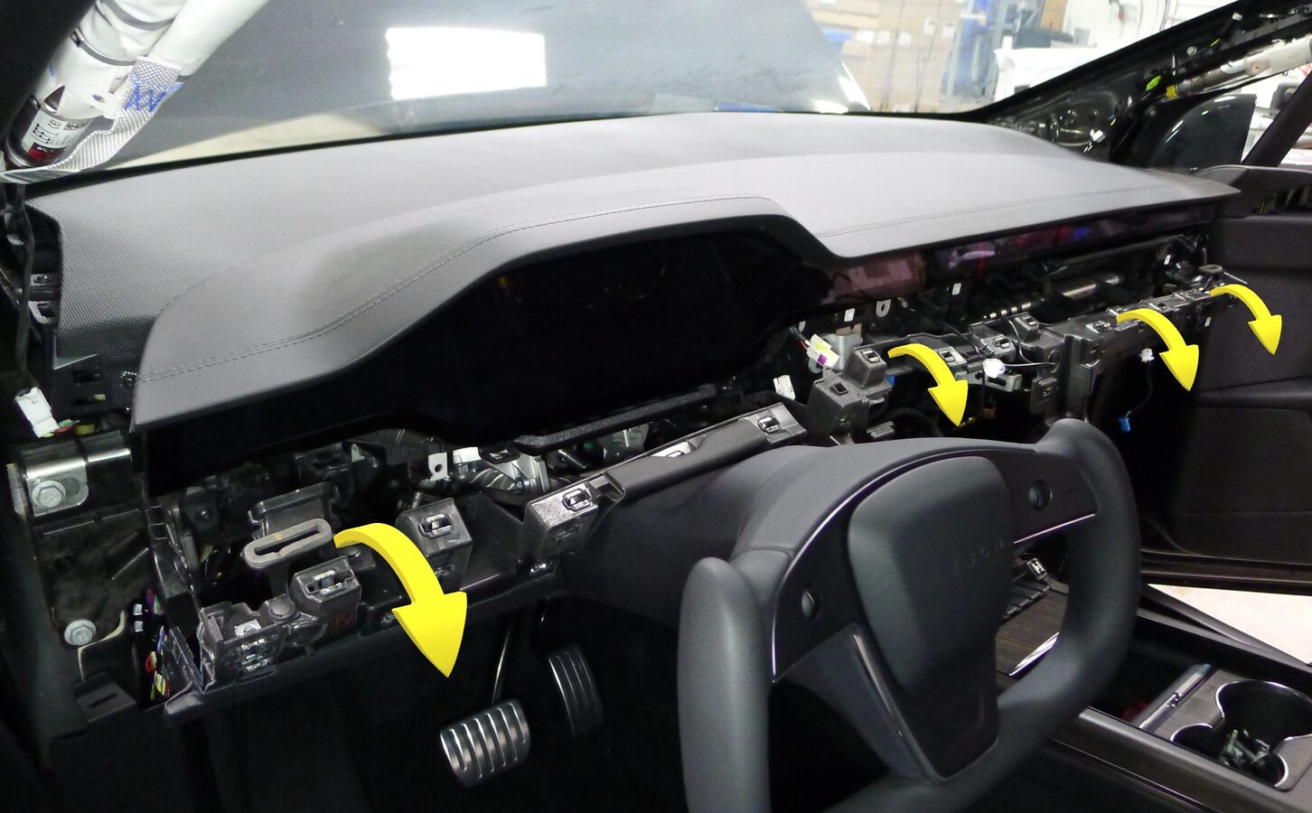
Position lower instrument panel assembly away from IP sub-assembly
注6x datums, Move top edge as far rearward as possible without excessive stress on assembly
-
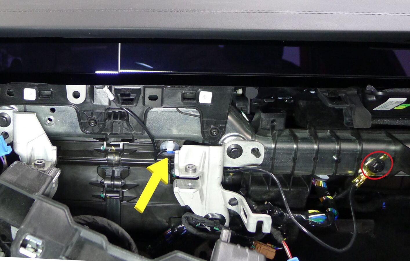
Release IP ground harness
注1x clip, 1x bolt, 10mm, 9 Nm, Note routing behind center display RH bracket. If using part revision 1562948-70-D on a Non-AP4 vehicle, add ground strap 1679240-00-A to aero lens assembly
-
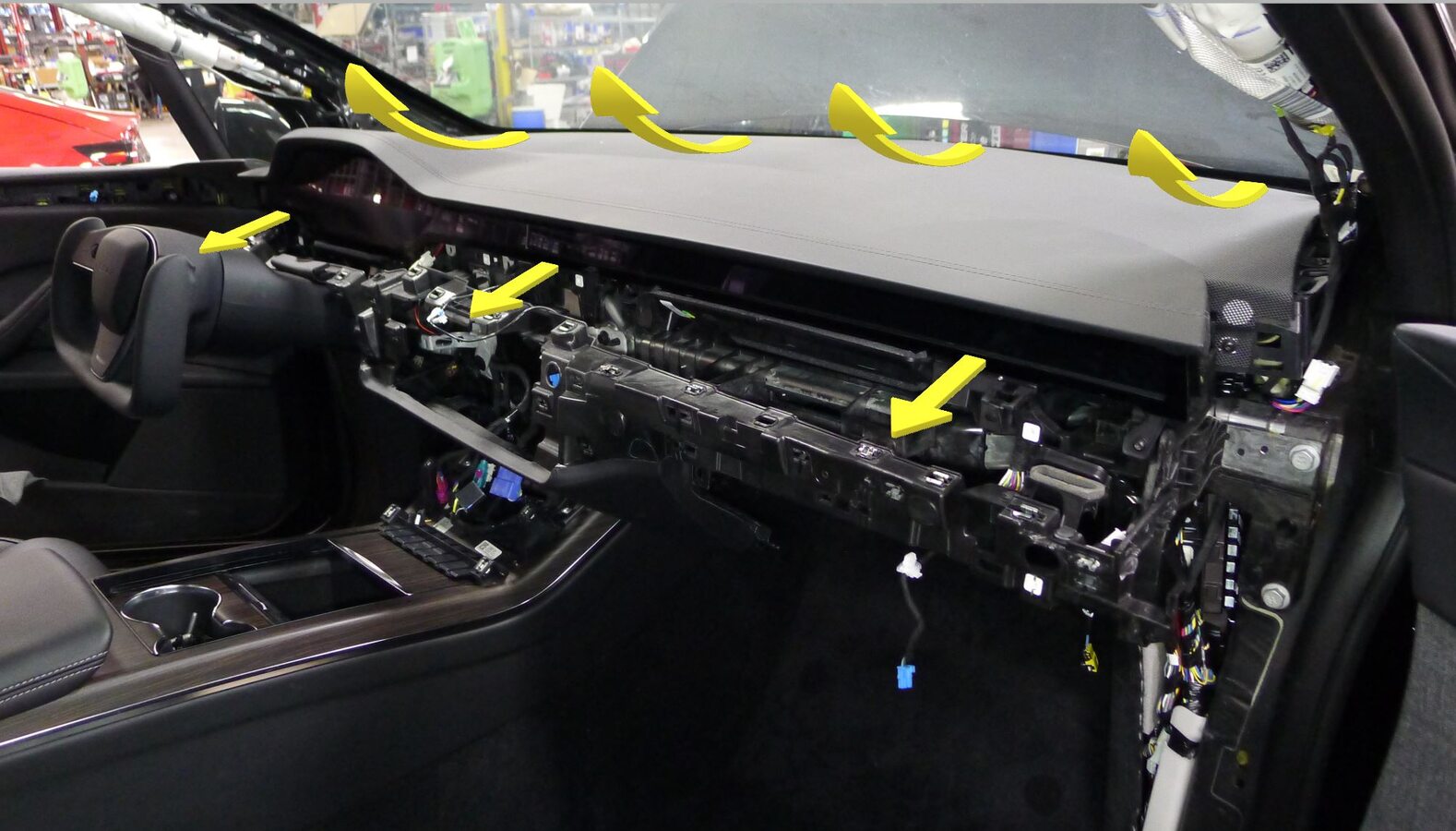
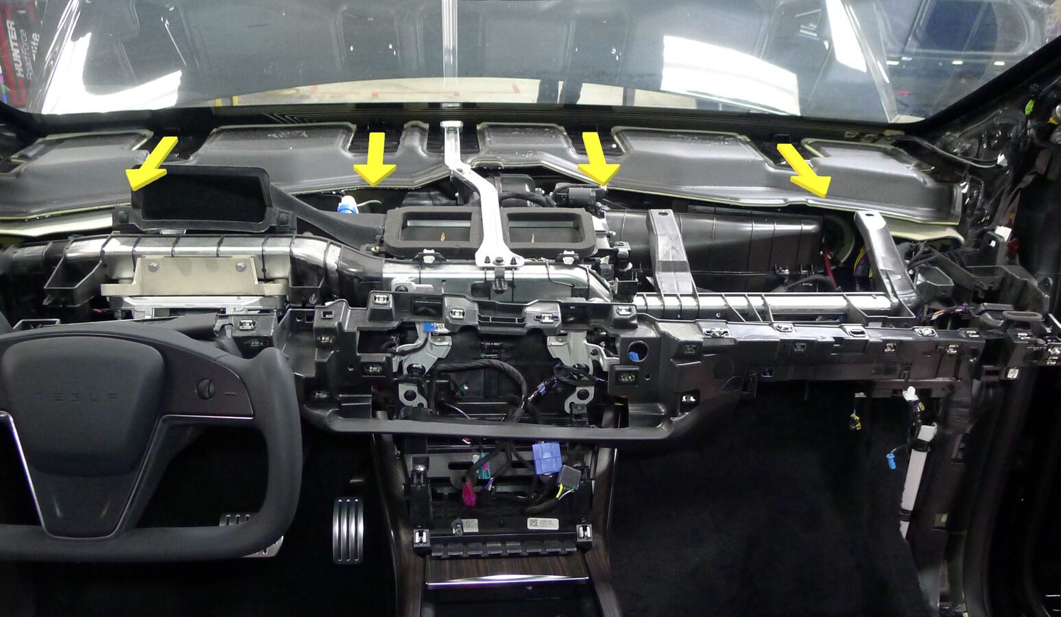
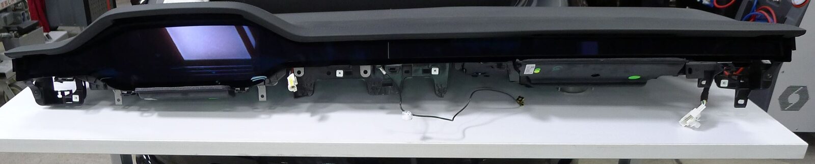
Remove IP sub-assembly
注Slide IP sub-assembly rearward, Lift assembly up from IP carrier, Ensure airwave vents and passenger air bag are clear of lower IP assembly, Remove assembly out through RH front door, Recommend assistance as needed
-
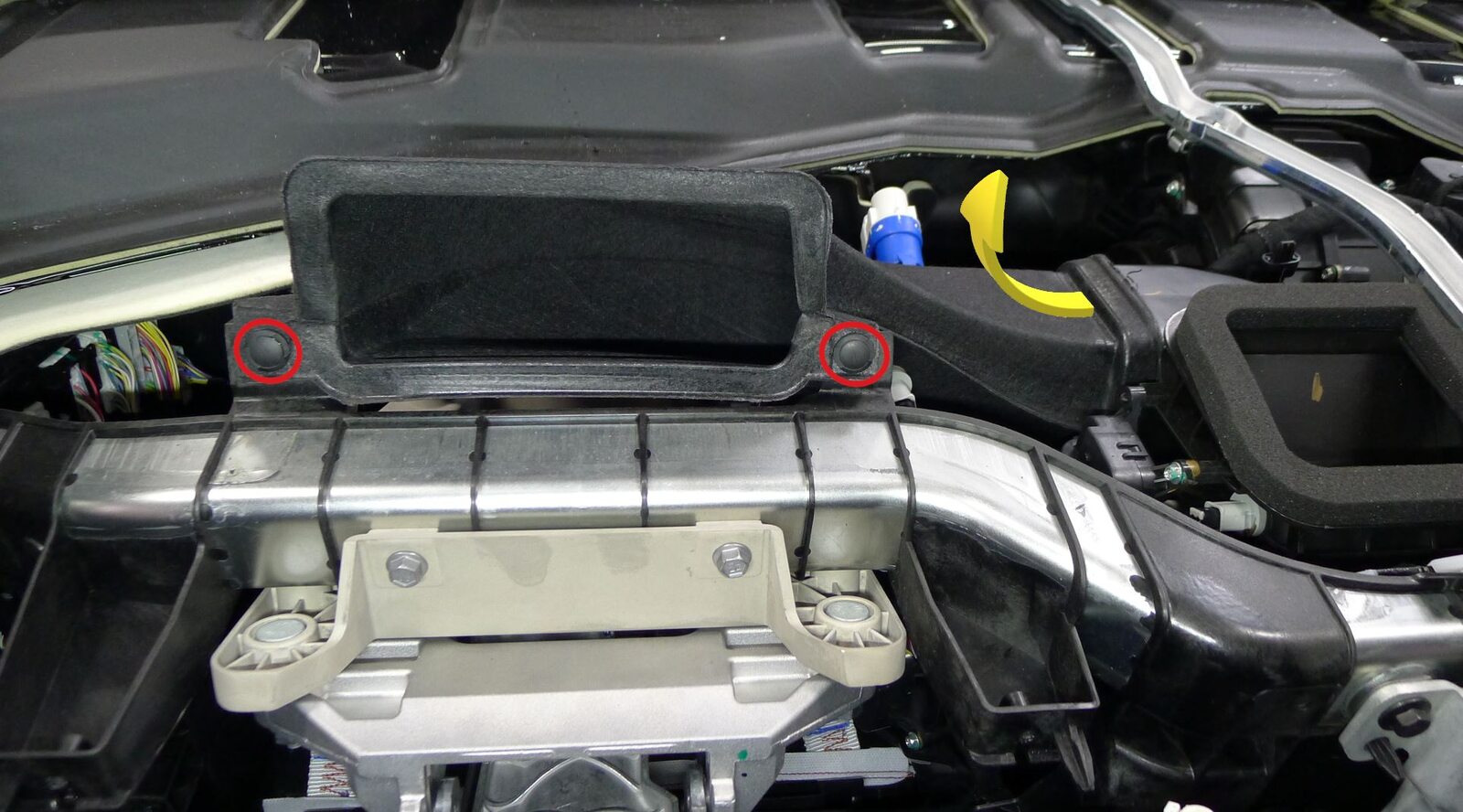
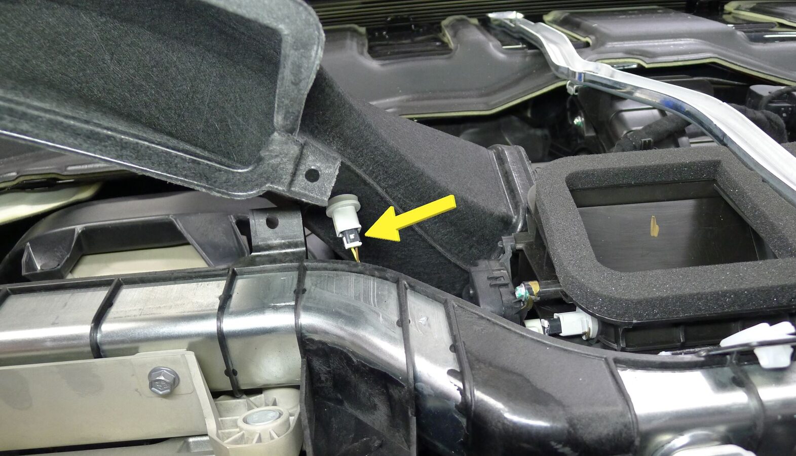
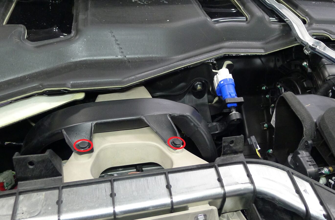
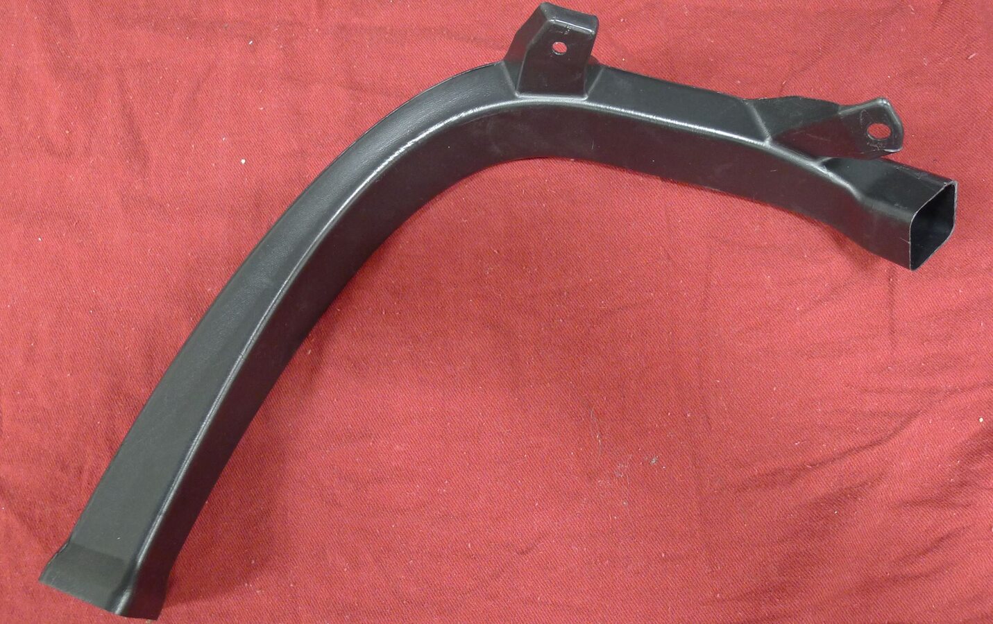
Remove driver IP air vent duct
注2x rivets, 1x connector, Slide outboard and up out of HVAC unit assembly
-
Remove driver floor jumper left foot duct
注2x push clips
-
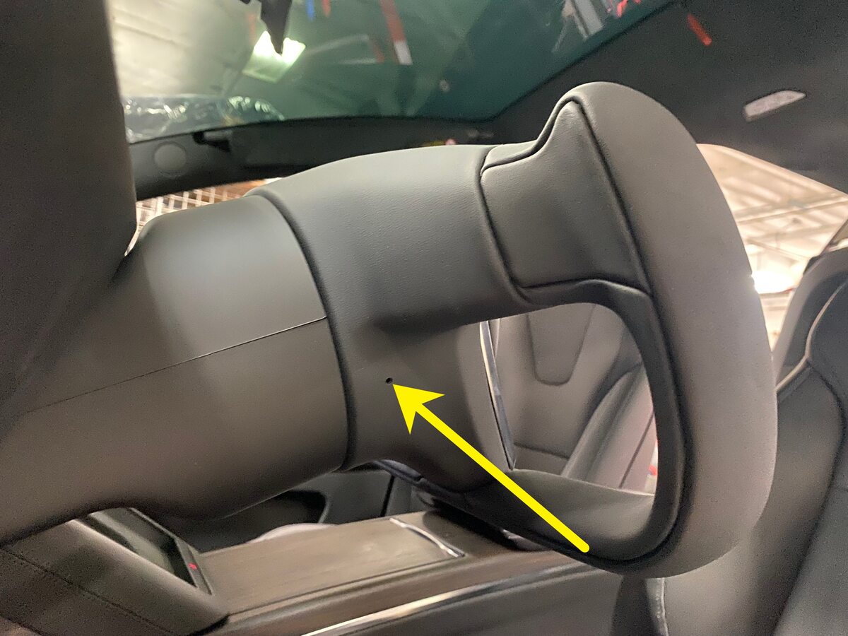
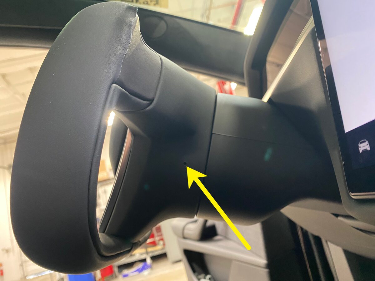
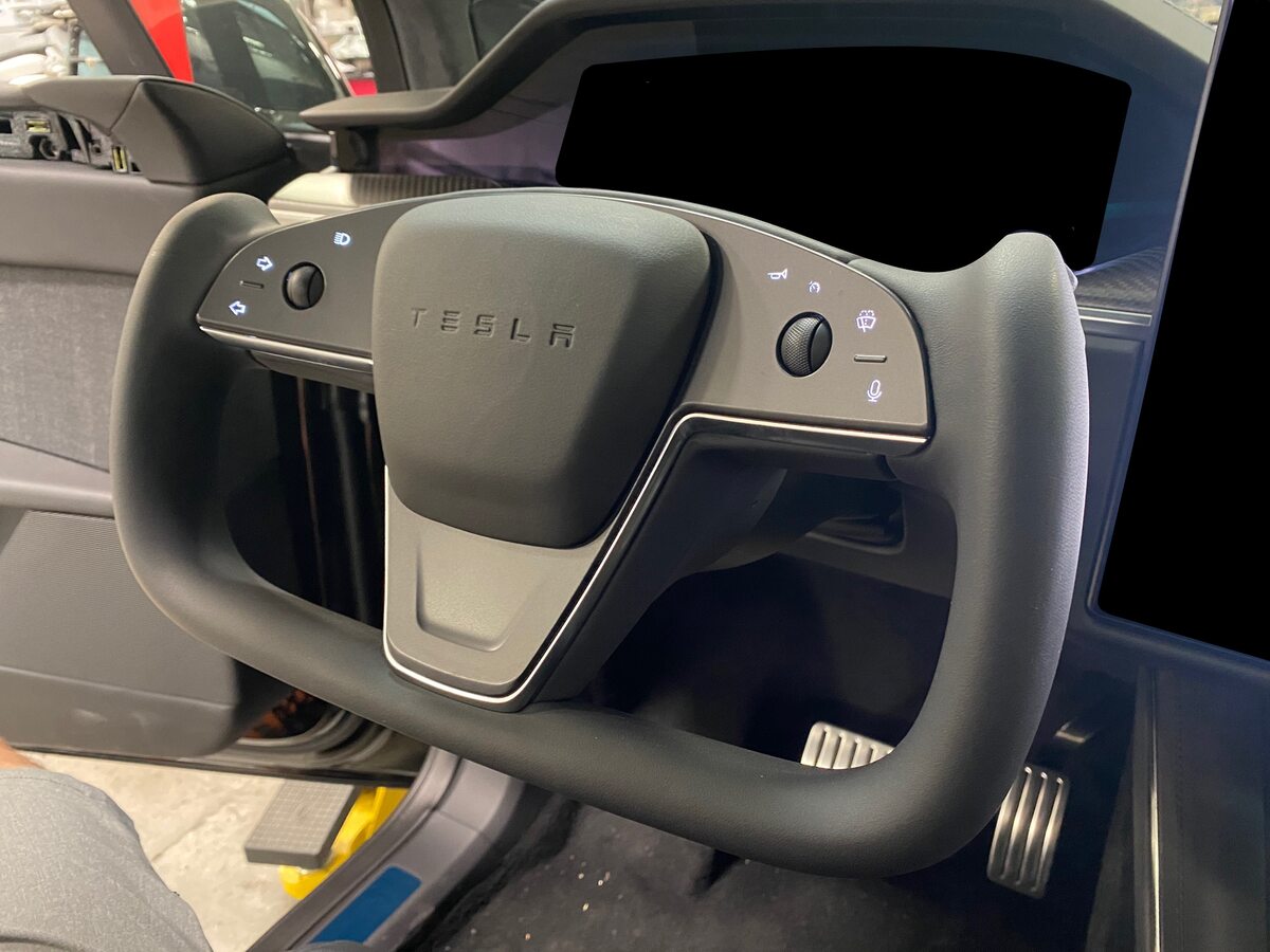
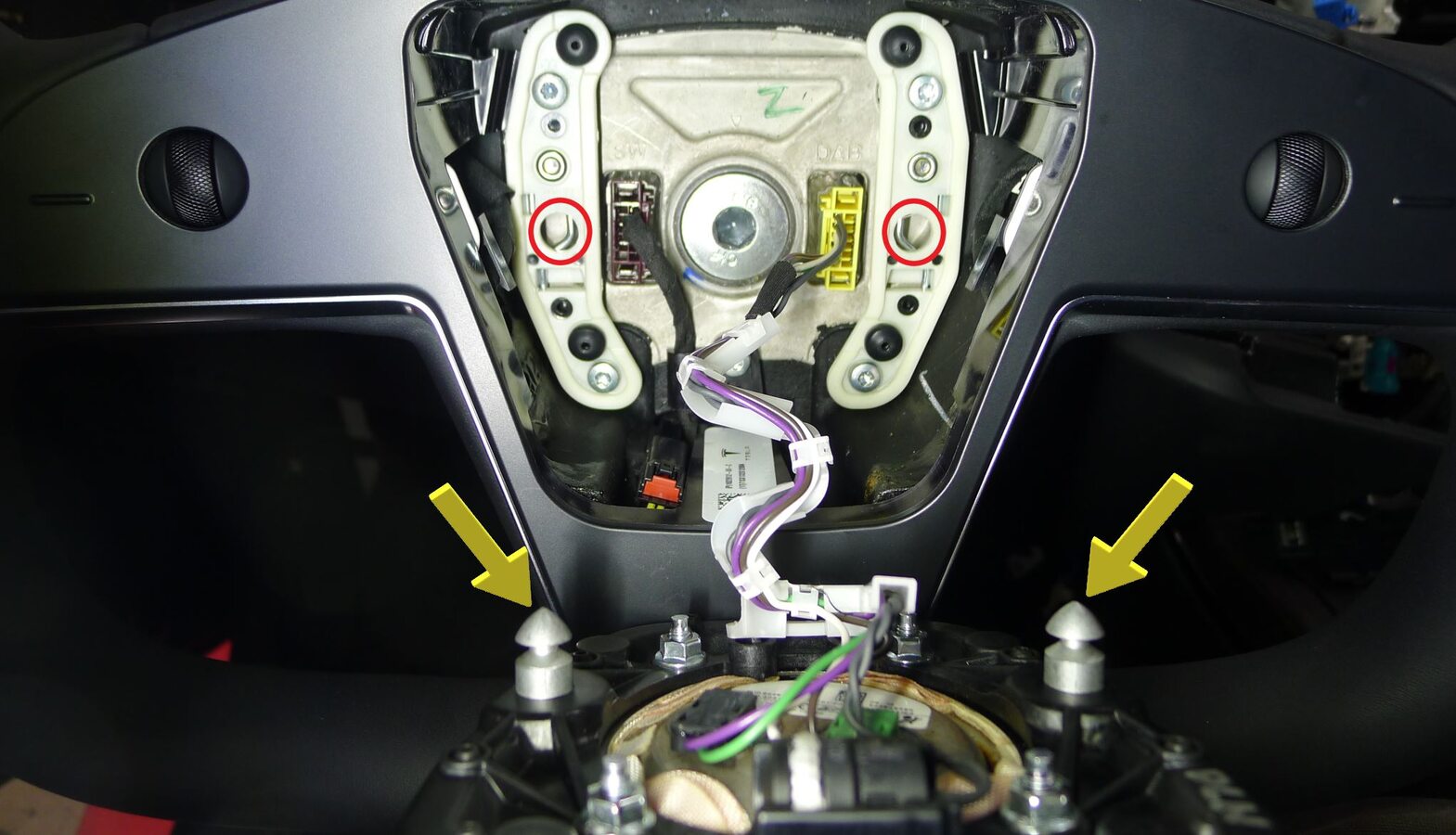
Release spring clip securing driver air bag assembly to steering wheel and pull driver air bag assembly away from steering wheel
注2x spring clips, 2x datums, Press the spring simultaneously from two access holes to release, Access holes located at 4 and 8 o’clock position, Do not insert tool too far as air bag connector could be damaged
-
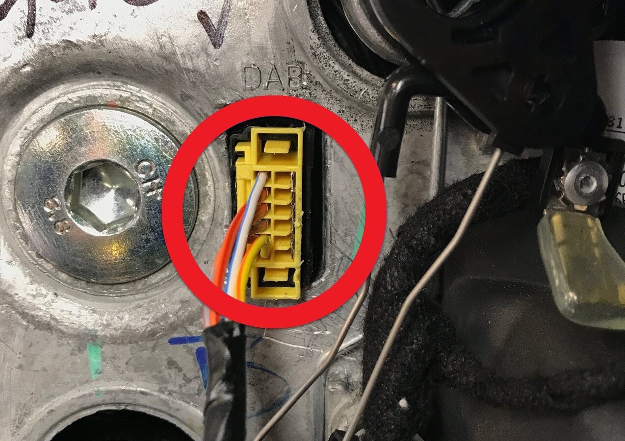
Disconnect driver air bag connector and remove driver air bag assembly
注1x connector
-
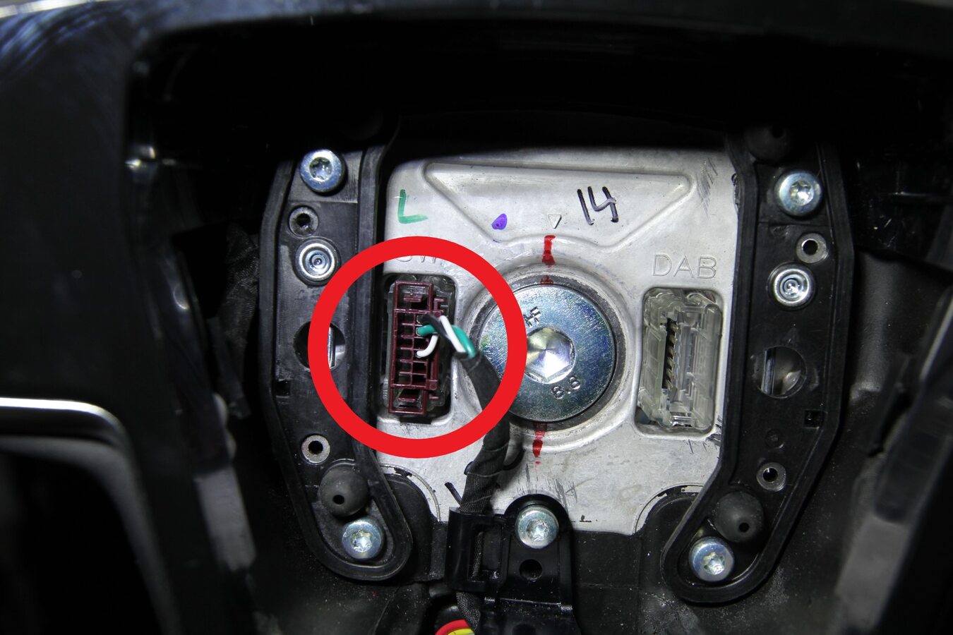
Disconnect steering wheel connector
注1x connector
-
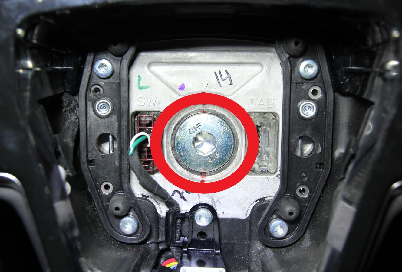
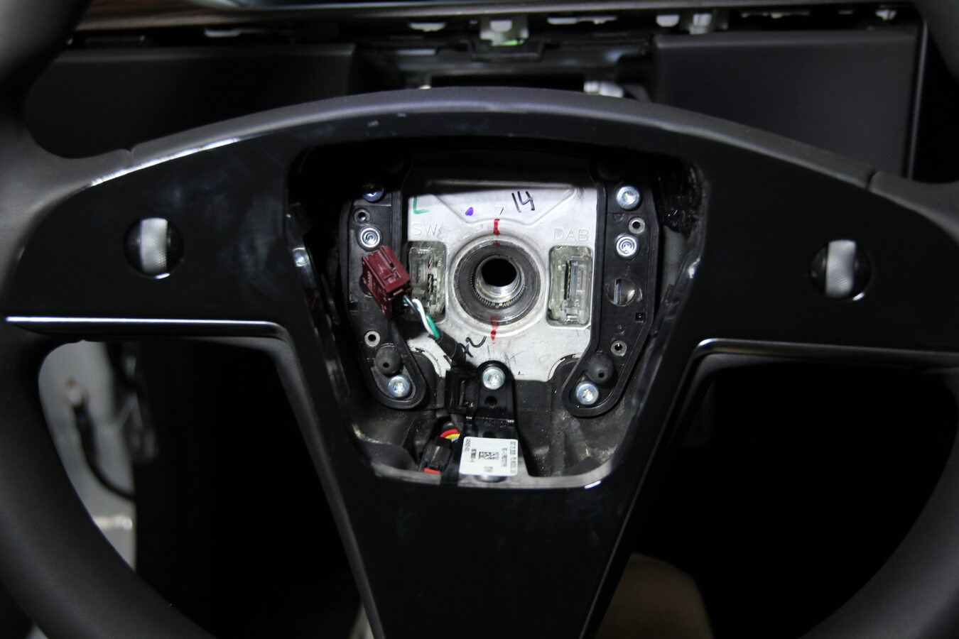
Remove bolt that secures the steering wheel to the column
注1x patch bolt, 10mm allen, 80 Nm, Discard after removal
-
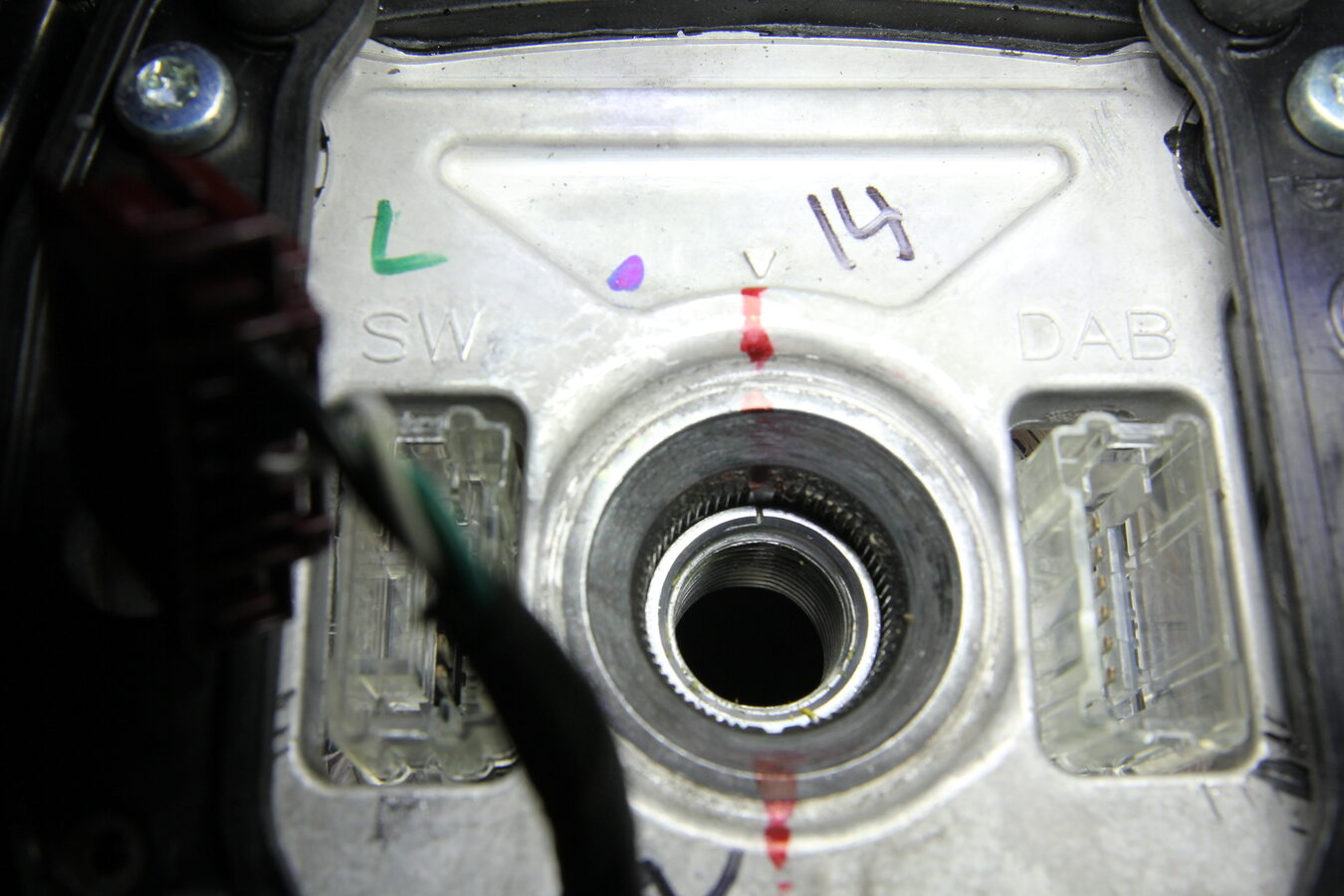
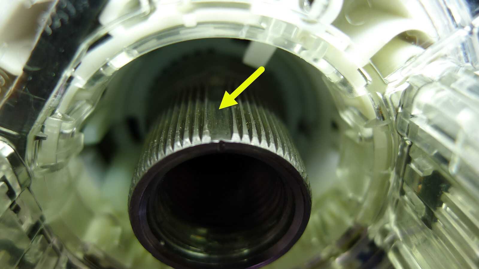
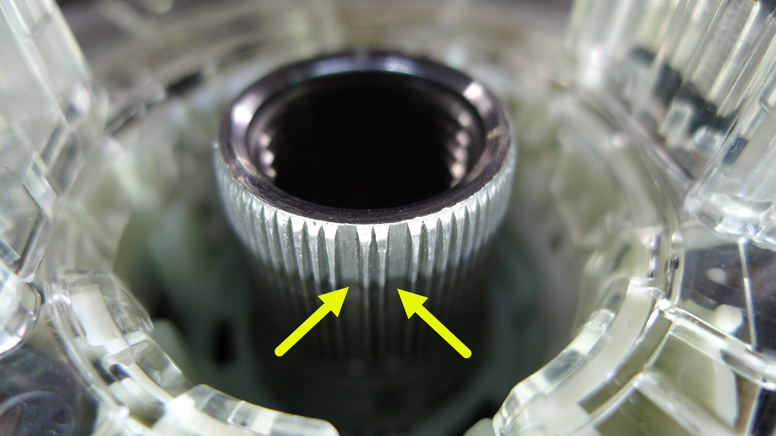
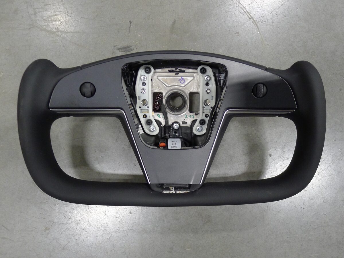
Remove steering wheel
注Note that the steering wheel is splined to the column
-
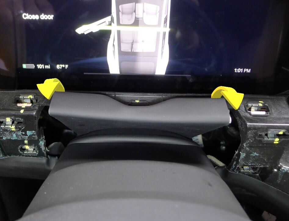
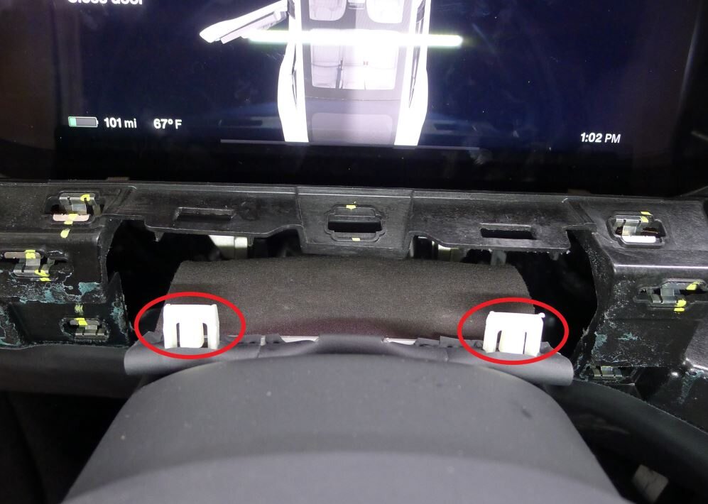
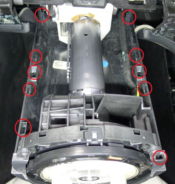
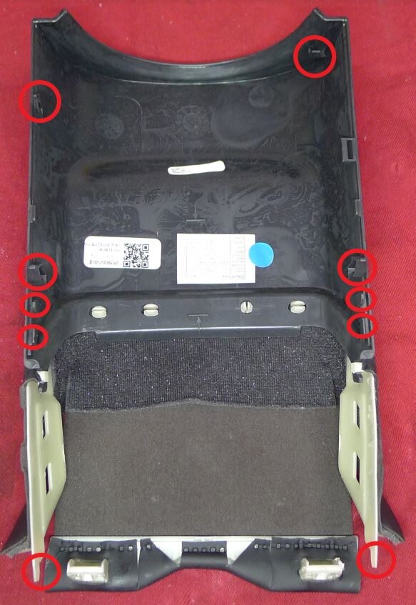
Pull upward to release steering column upper shroud from lower shroud
注6x clips, 4x datums
-
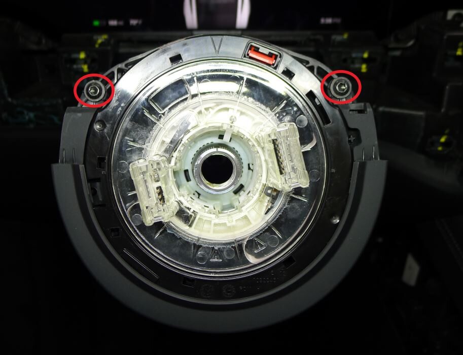
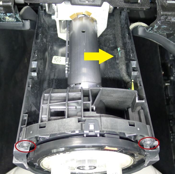
Remove lower shroud to steering column
注2x screws, T20, 1.5 Nm, 1x clip, 1x datum, Slide lower shroud rearward to release datum
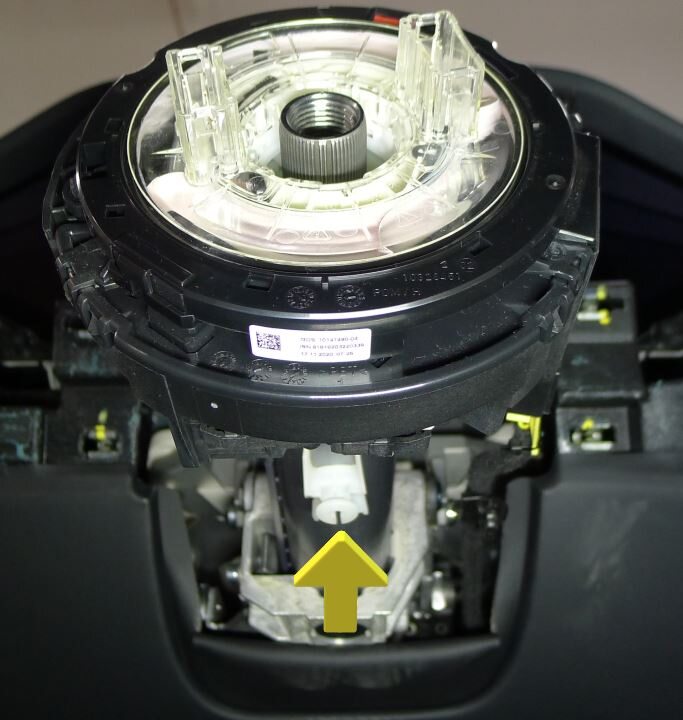
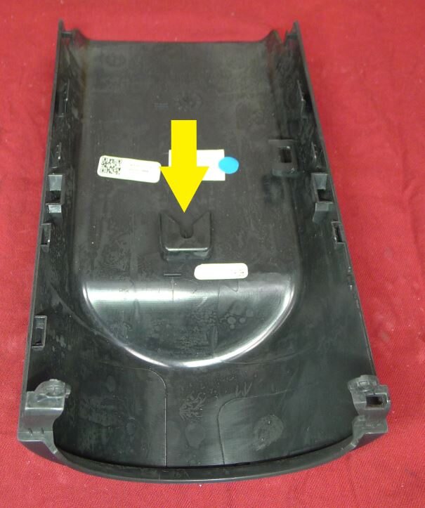
-
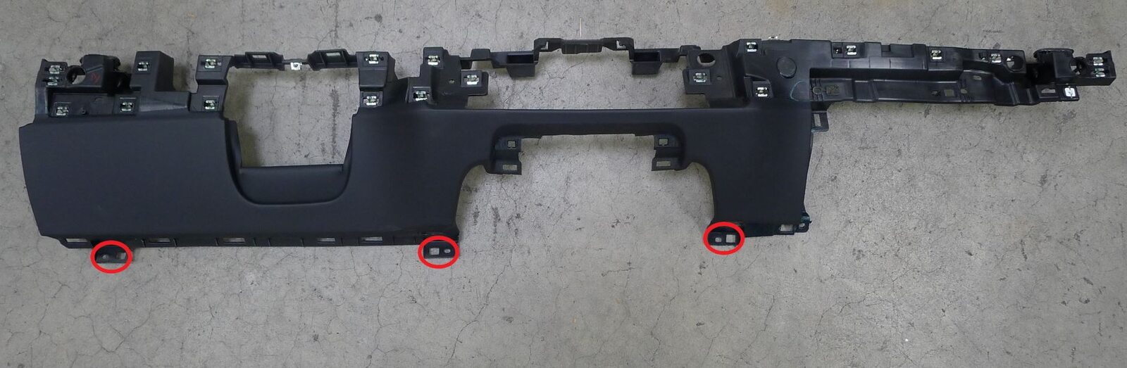
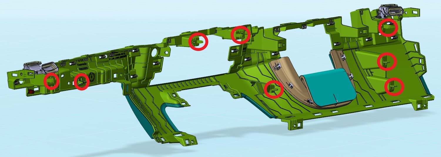
Remove lower instrument panel assembly
注3x screws, T20, 3 Nm, 8x tabs, Remaining screws located at bottom of assembly, Release assembly and carefully guide over upper steering column
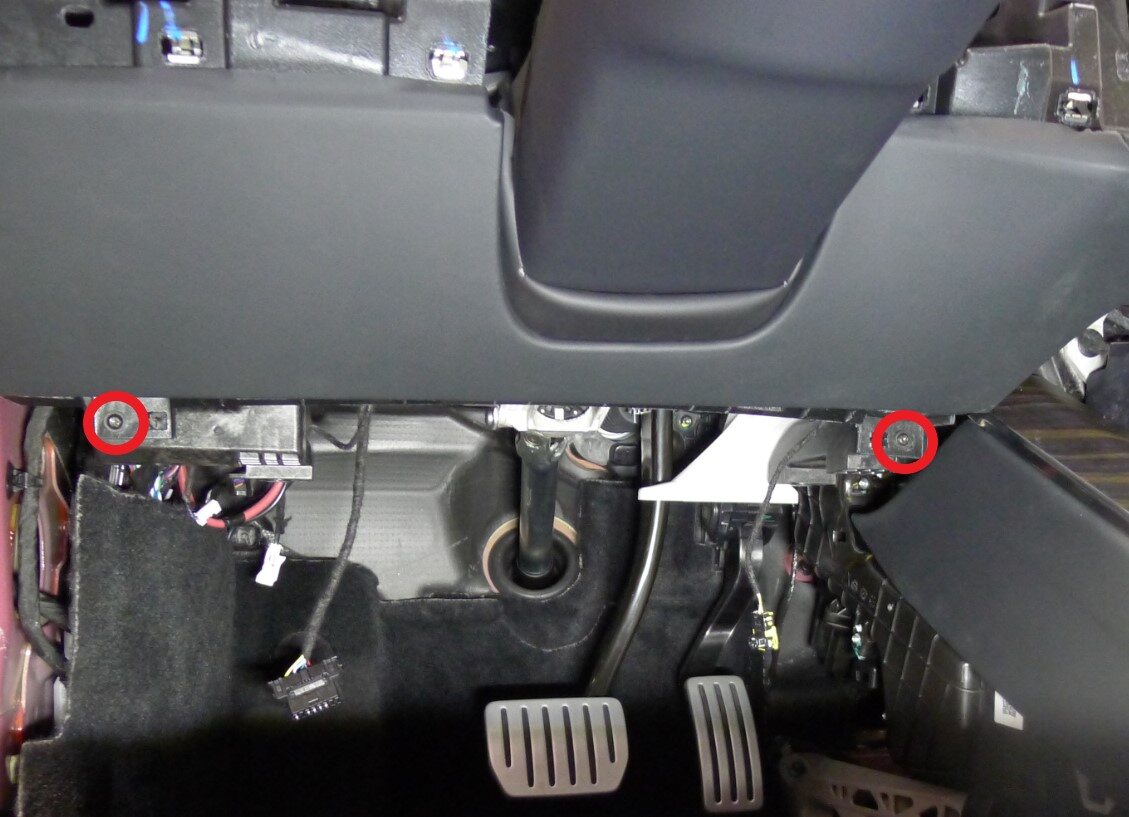
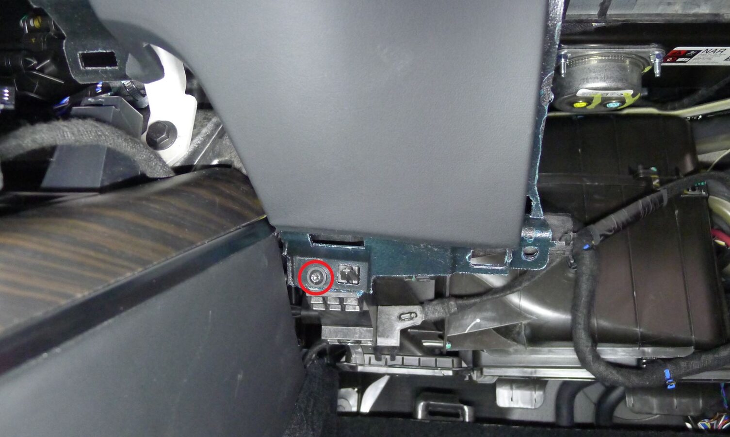
-
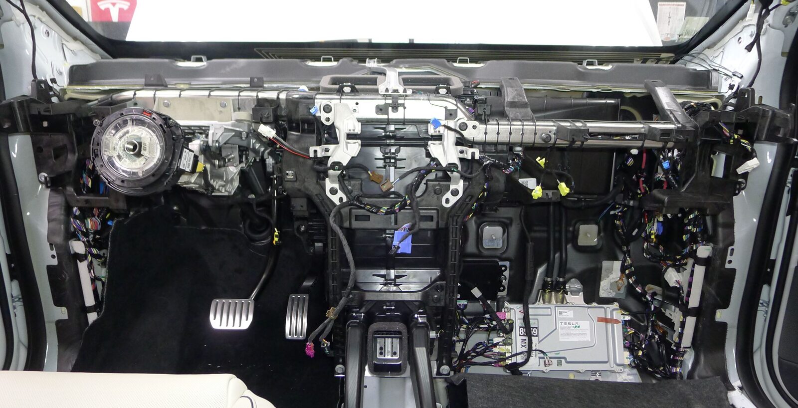
Release IP harness at LH and RH center display brackets
注4x clips

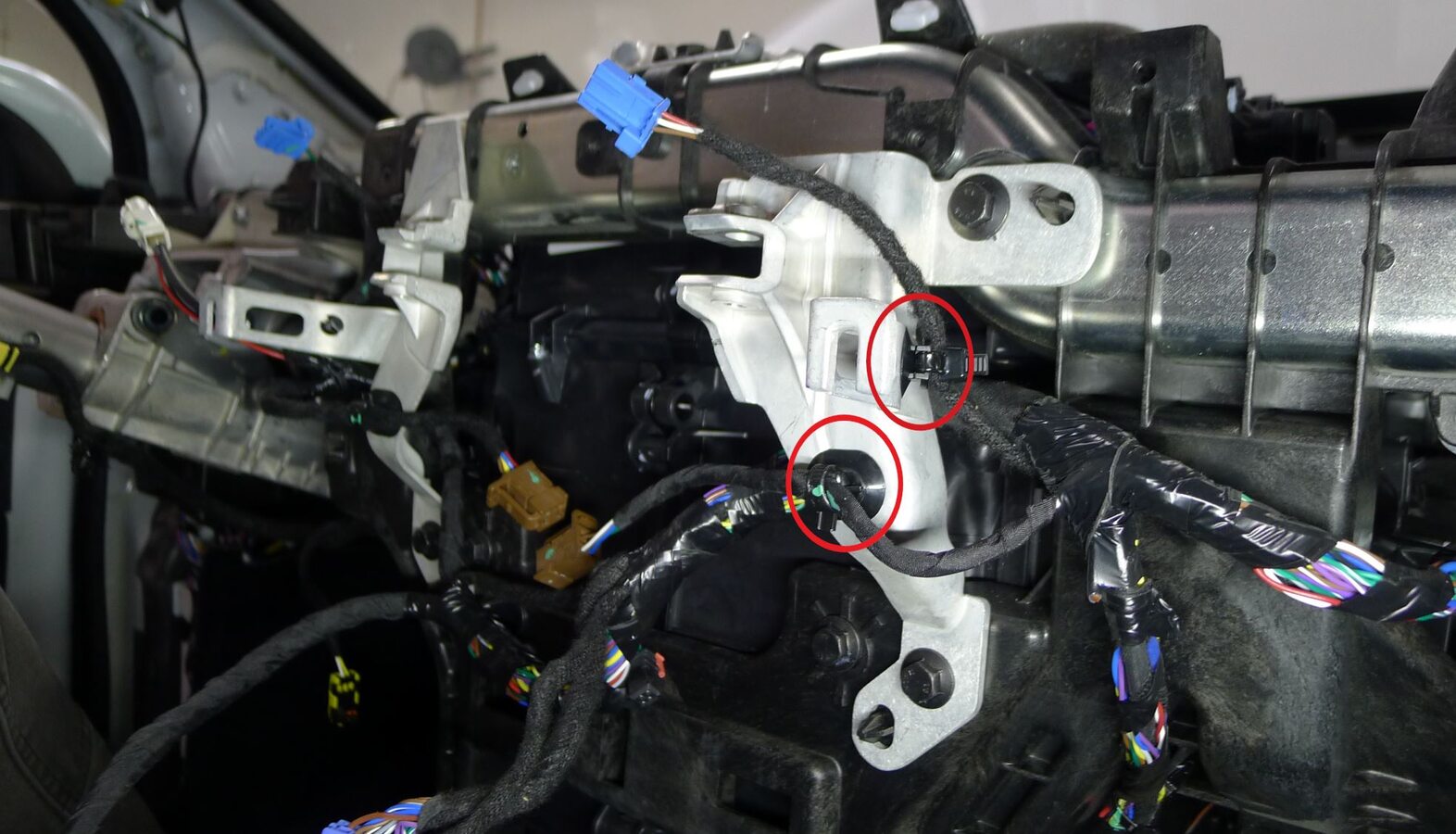
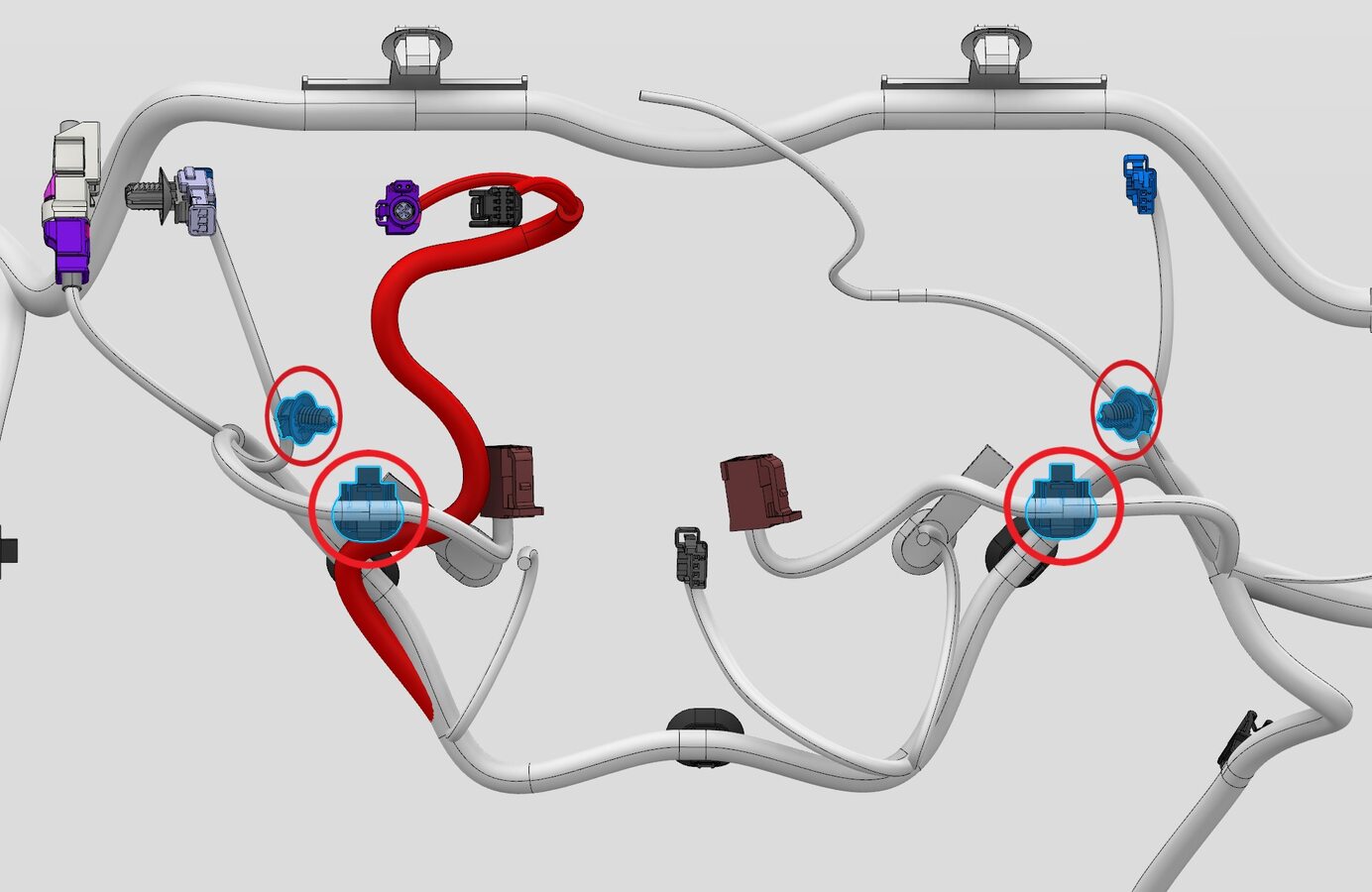
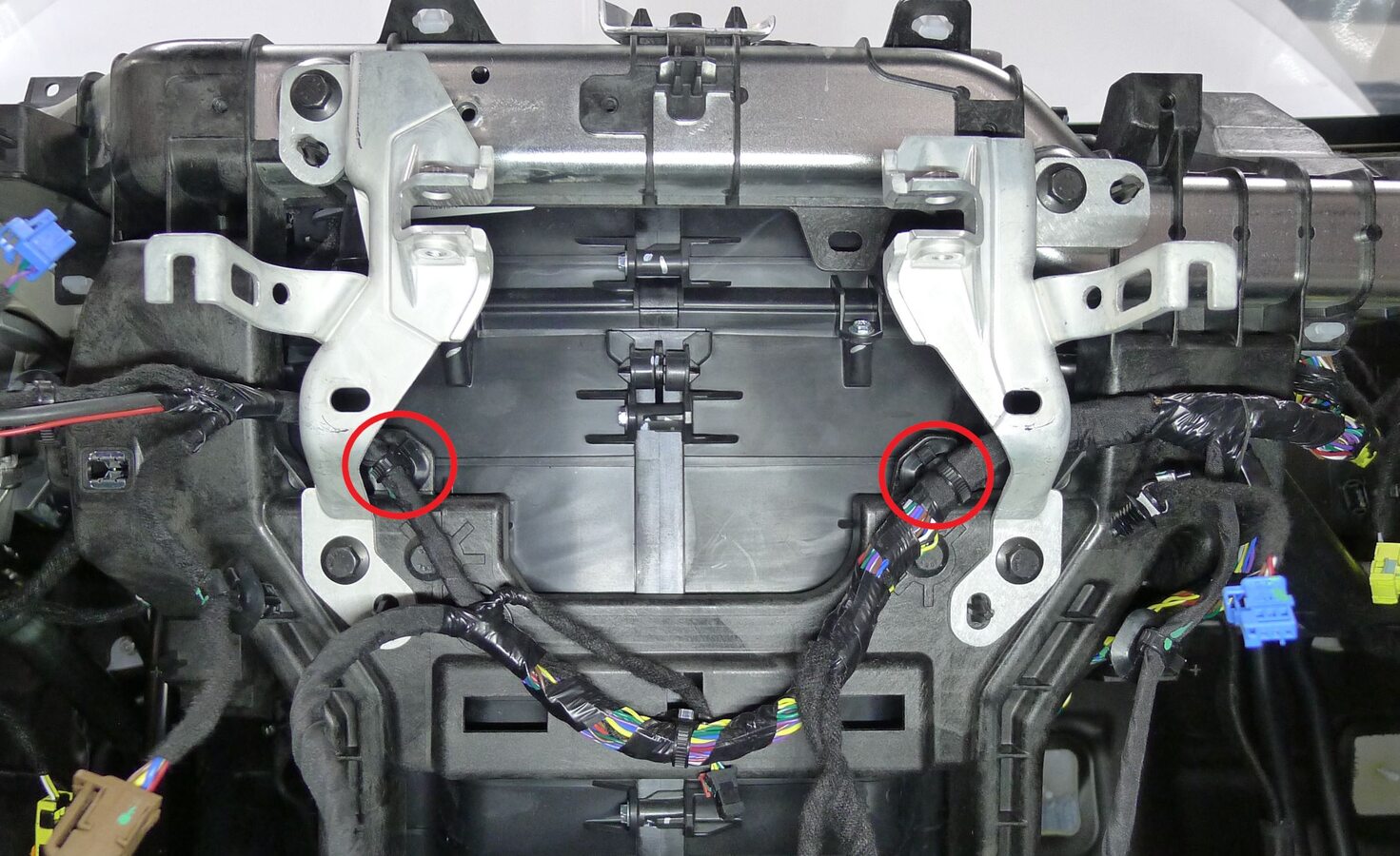
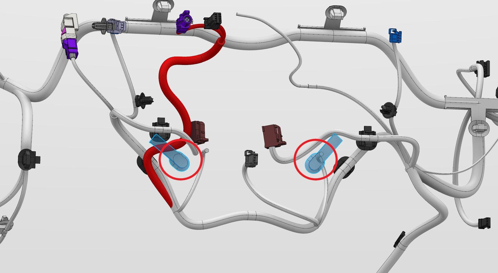
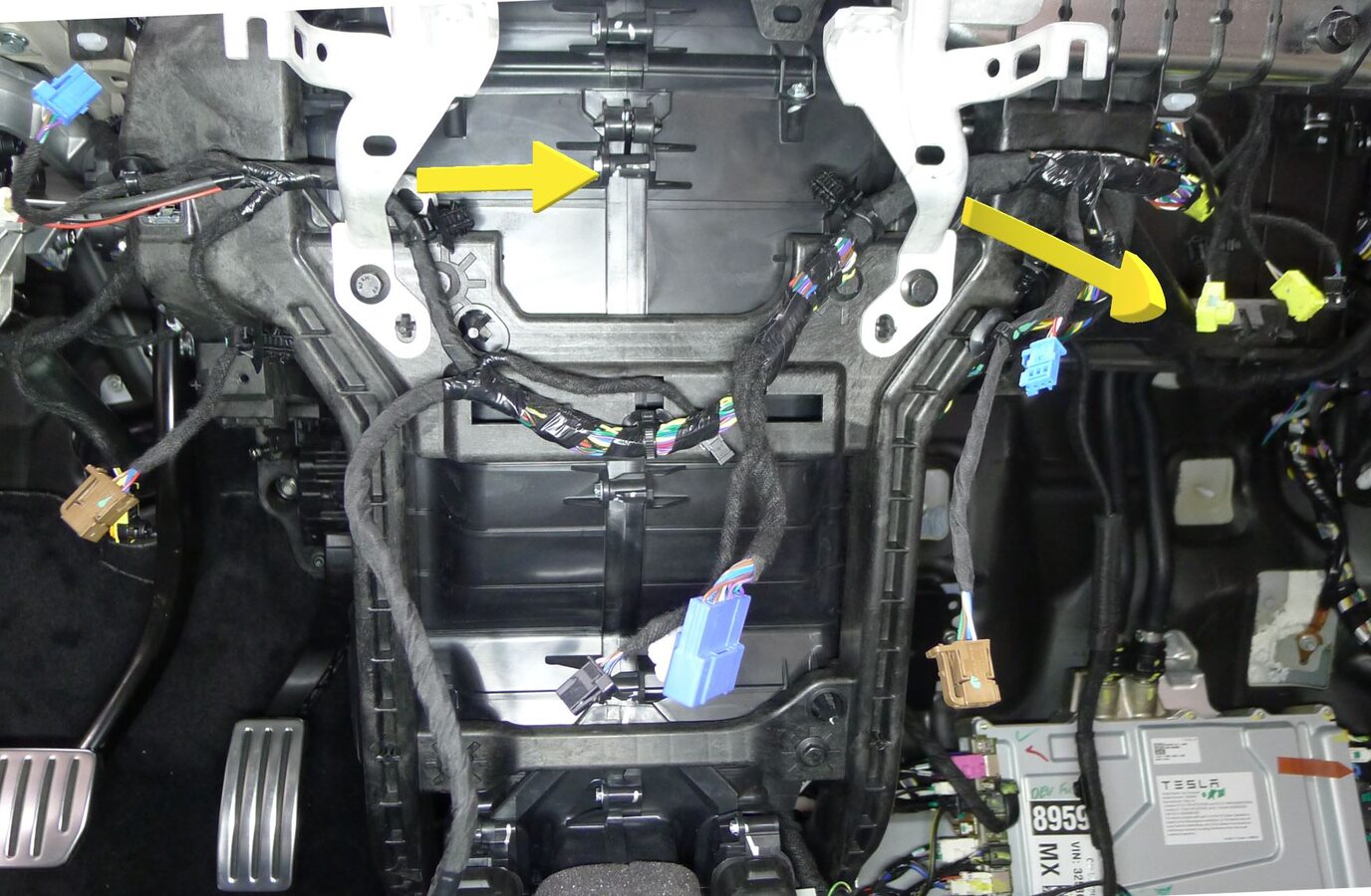
-
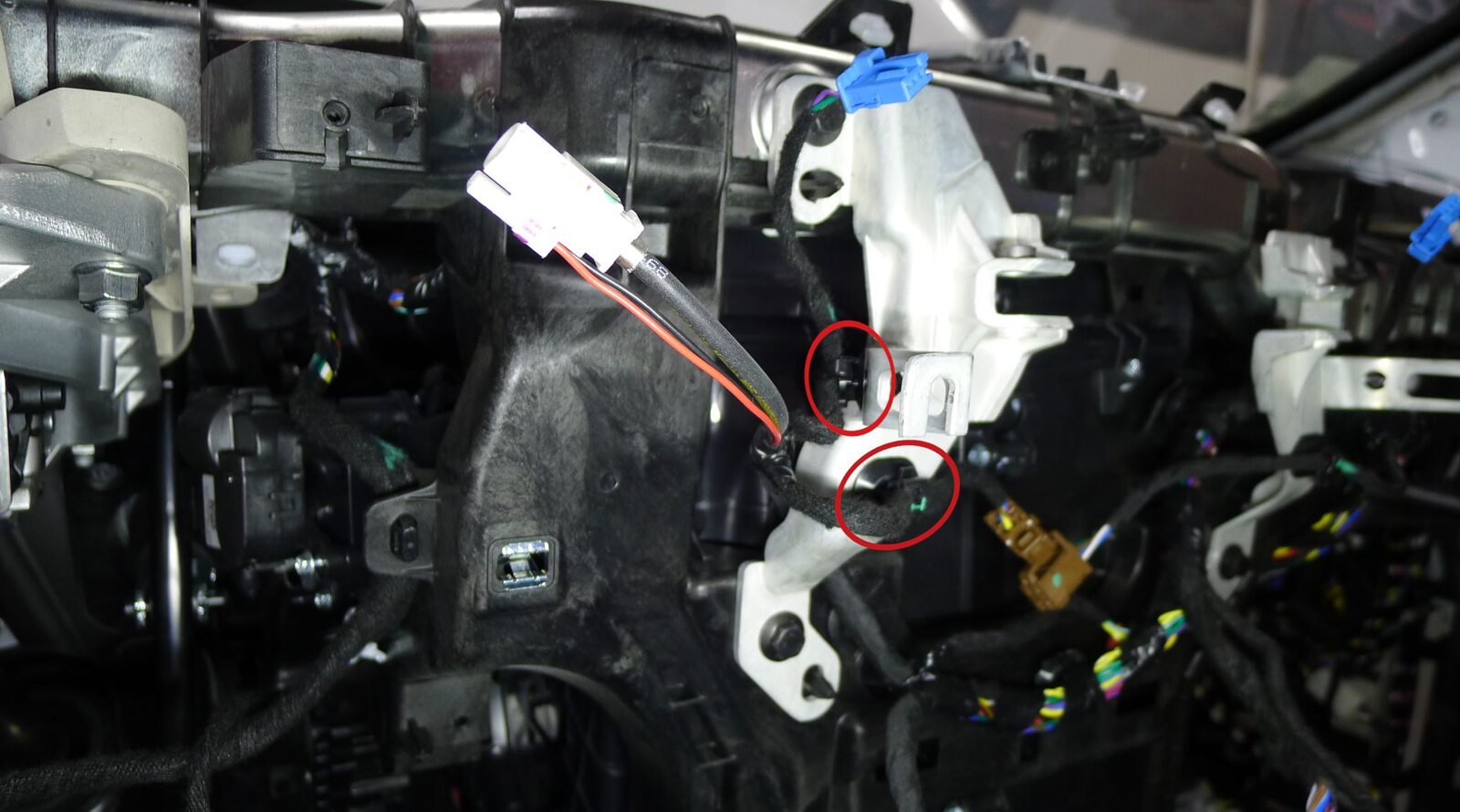
Release IP harness from center IP carrier
注2x clips, Once released maneuver IP harness behind both center display brackets into passenger side footwell
-
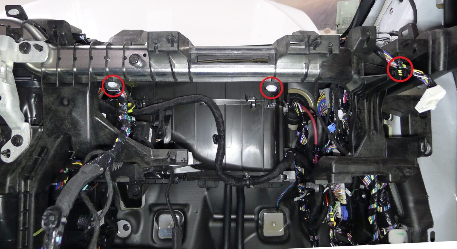
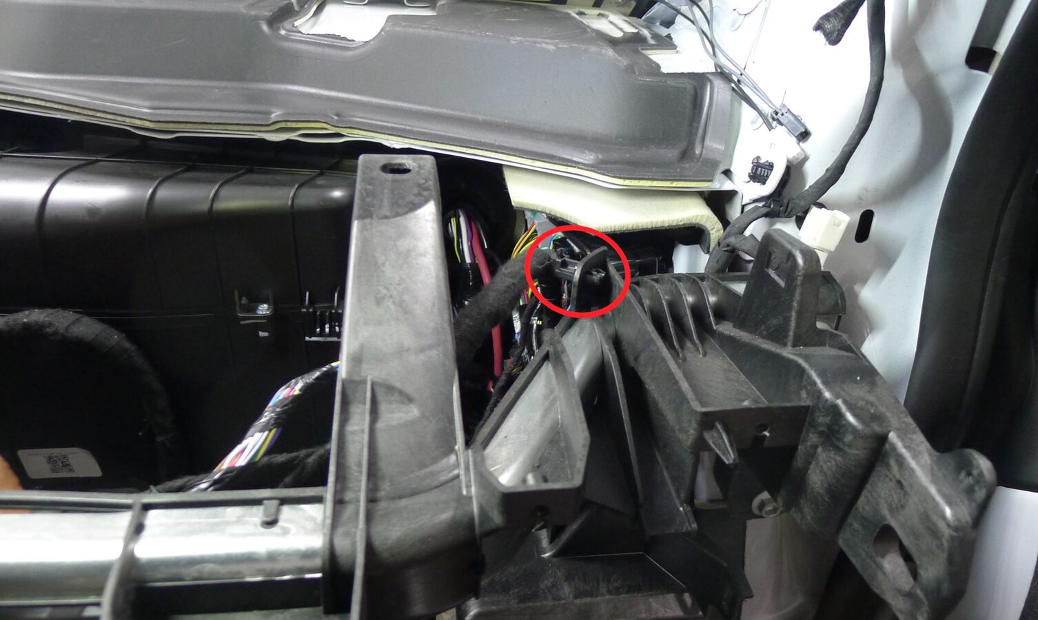
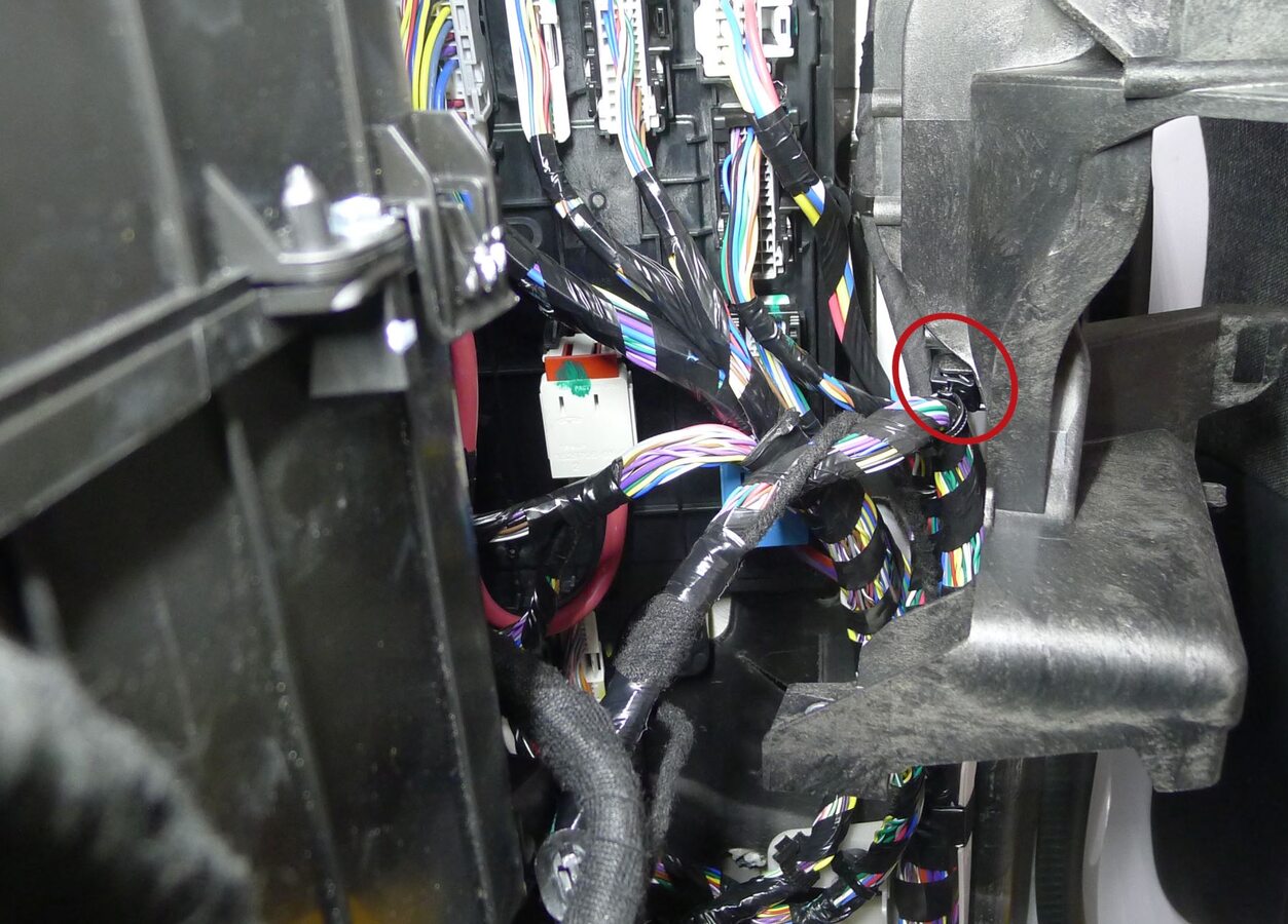
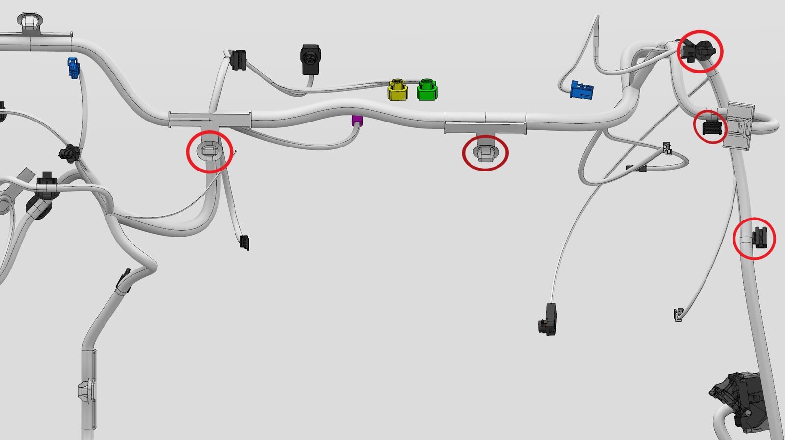
Release IP harness from RH IP carrier
注5x clips
-
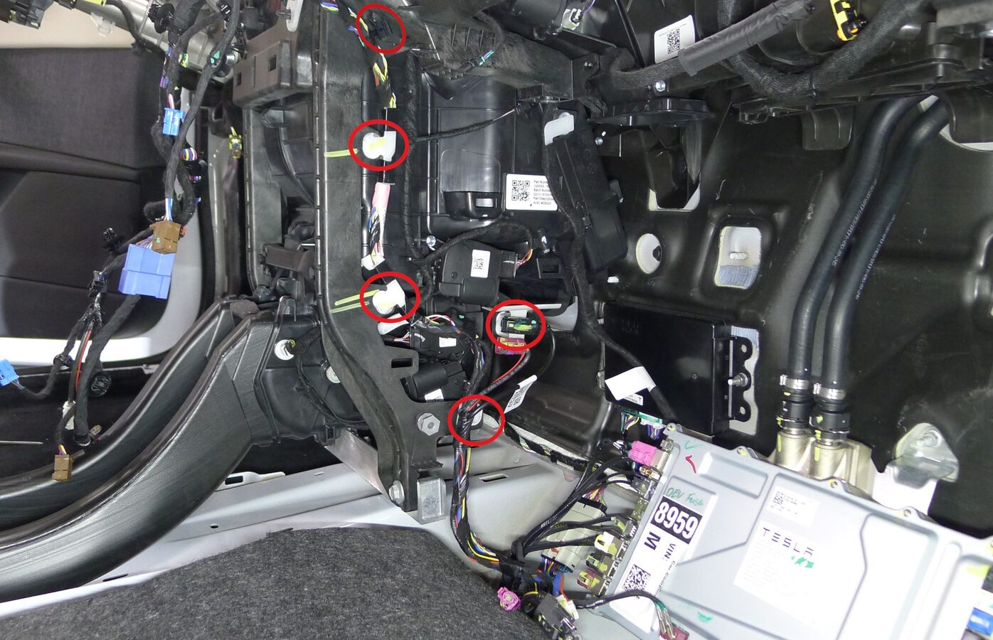
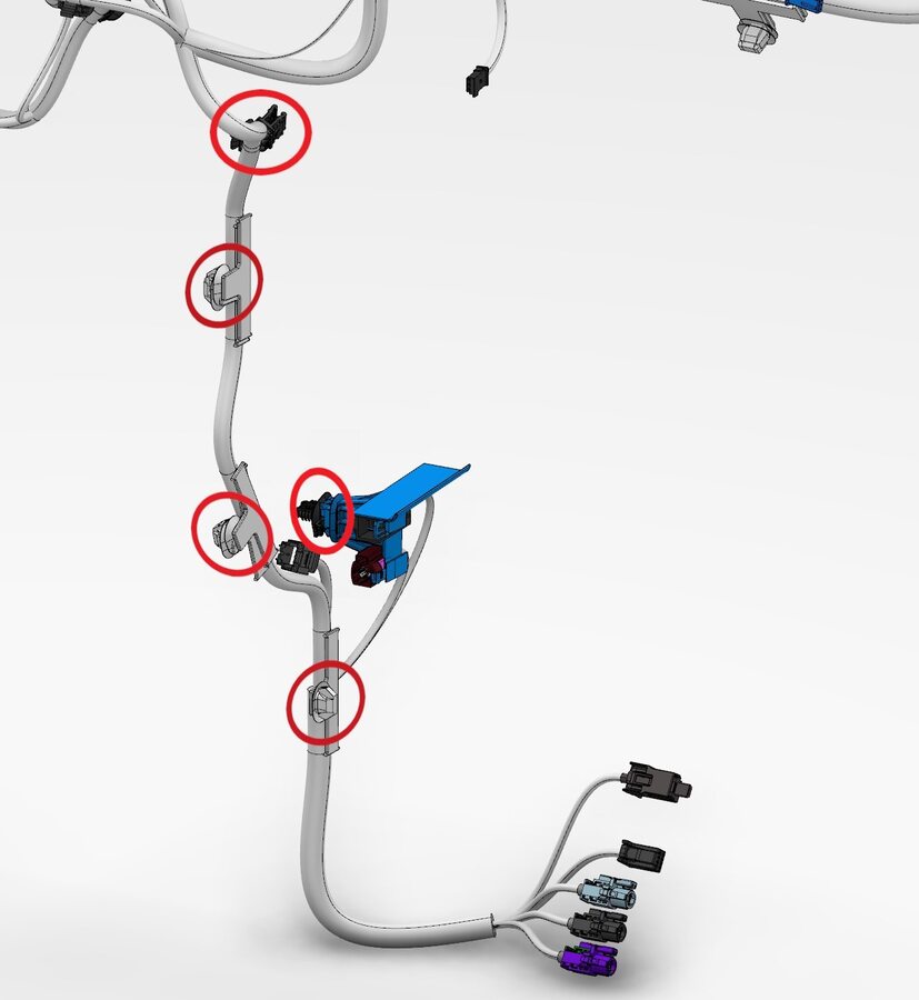
Release IP harness from lower center IP carrier
注5x clips
-
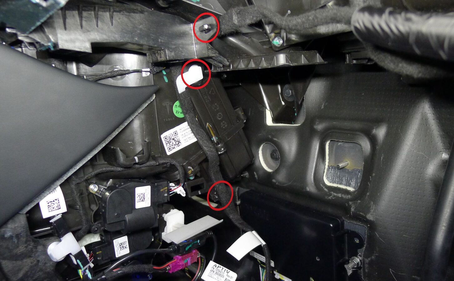
Release glove box USB cable from IP carrier
注3x clips
-
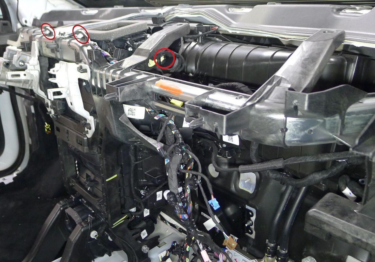
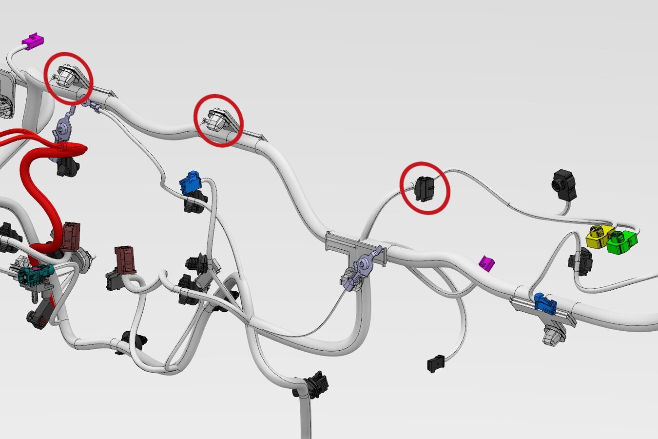
Release IP harness at upper center IP carrier
注3x clips
-
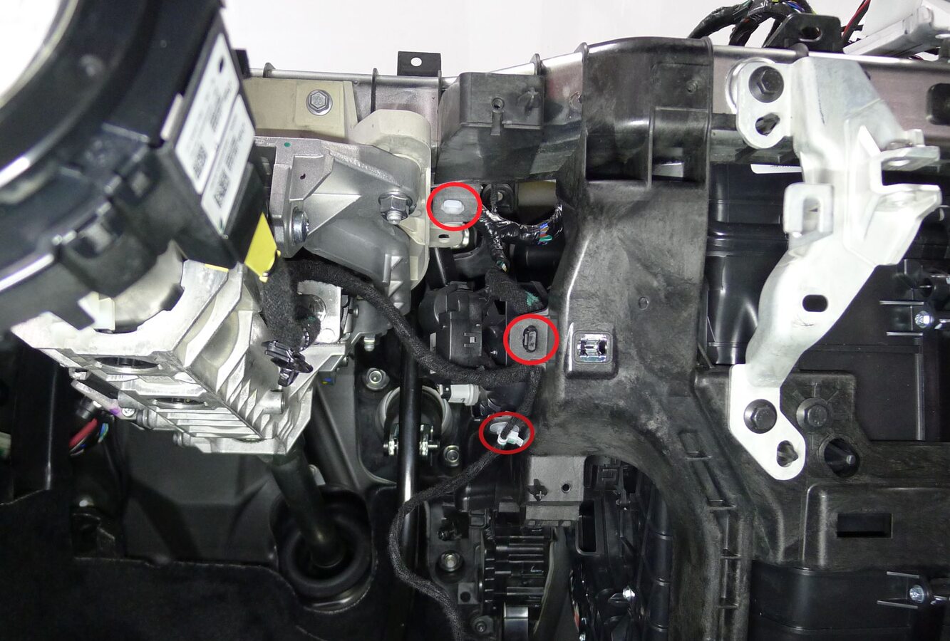
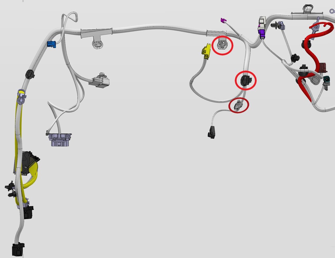
Release IP harness from LH center IP carrier
注3x clips
-
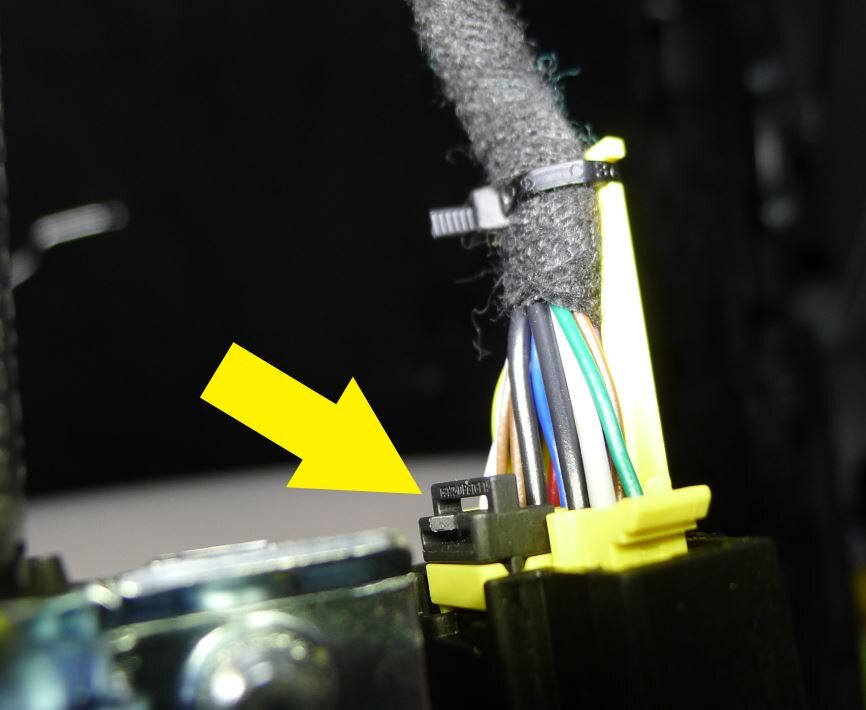
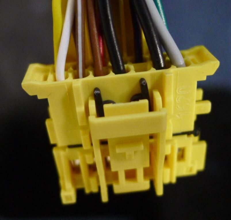
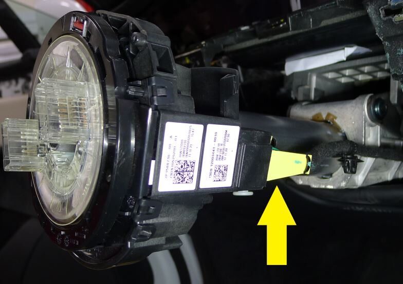
Disconnect steering column control module assembly connector
注1x connector, Remove retaining clip on the connector, release connector, then remove the remaining broken clip from connector, Discard retaining clip after removal, Originally installed clip is black, Replacement clip is orange
-
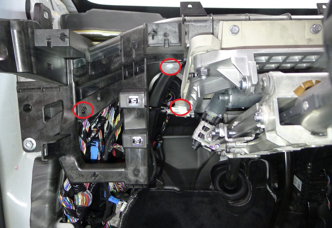
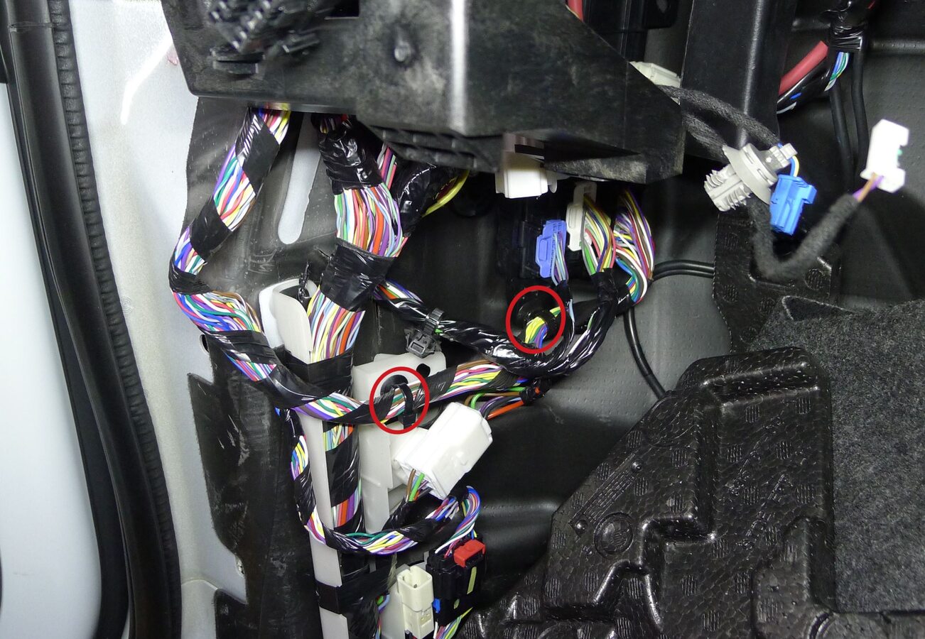
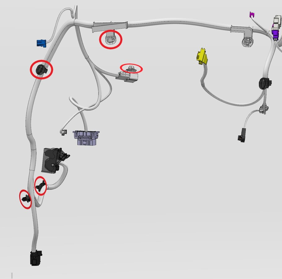
Release IP harness from LH IP carrier
注5x clips, 1x connector
-
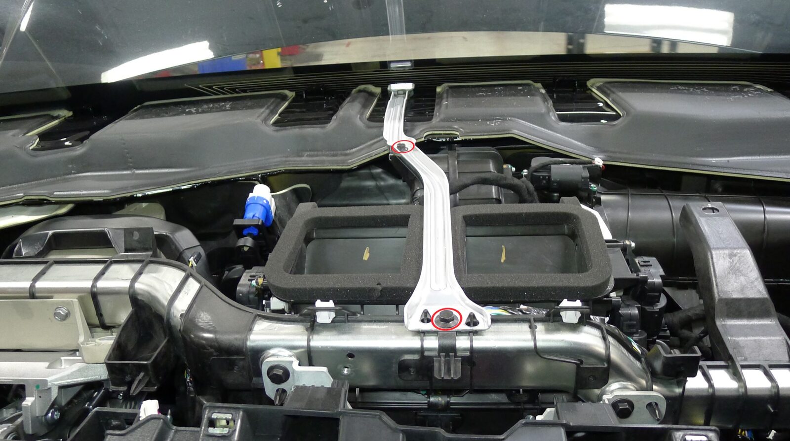
Release IP cowl link
注2x bolts, 10mm, 6 Nm, Only remove the bolts from the IP carrier and HVAC box
-
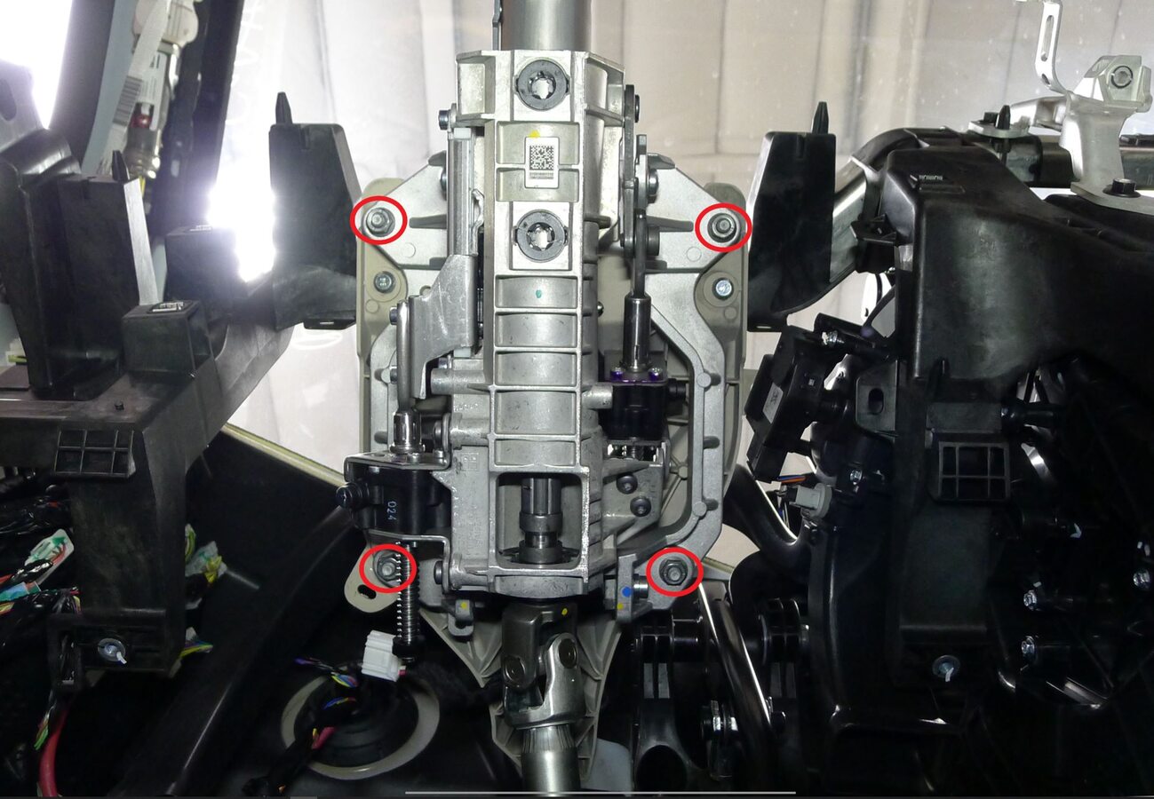
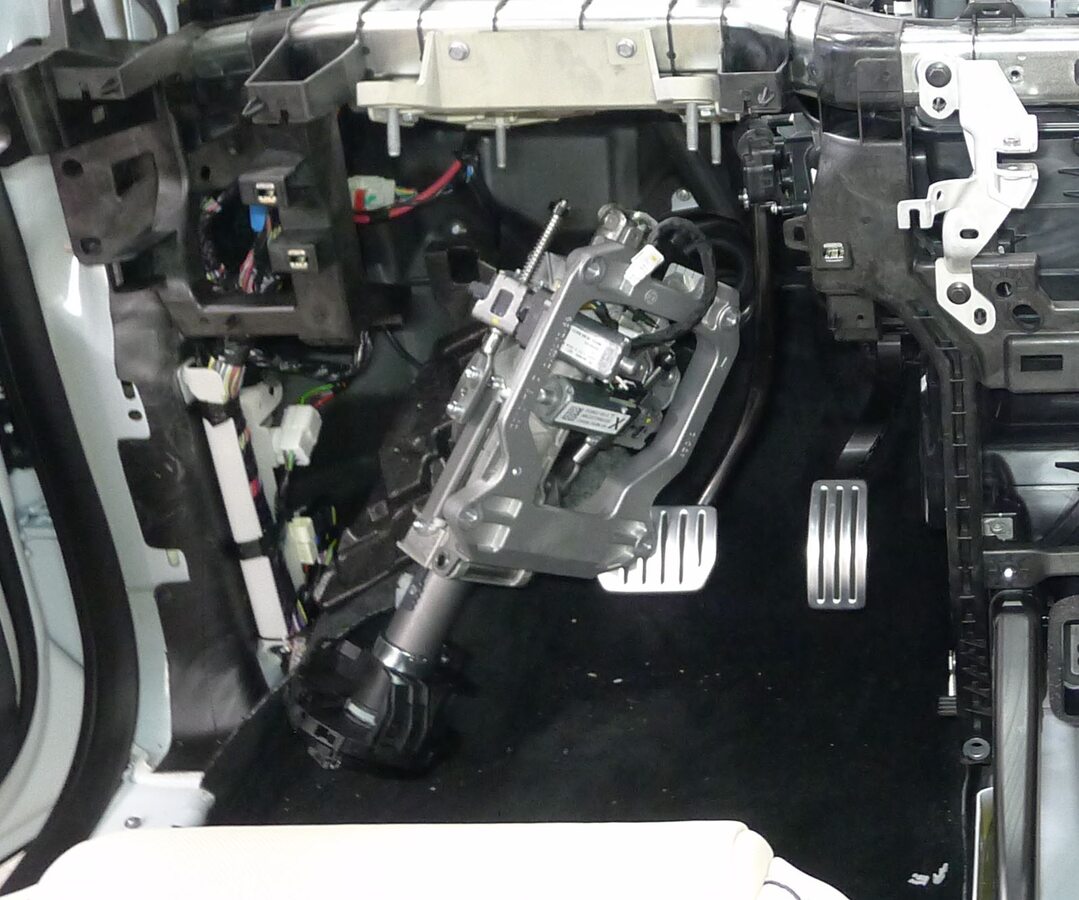
Release upper steering column from steering column bracket
注4x nuts, 13mm, 15 Nm, Rotate and set aside
-
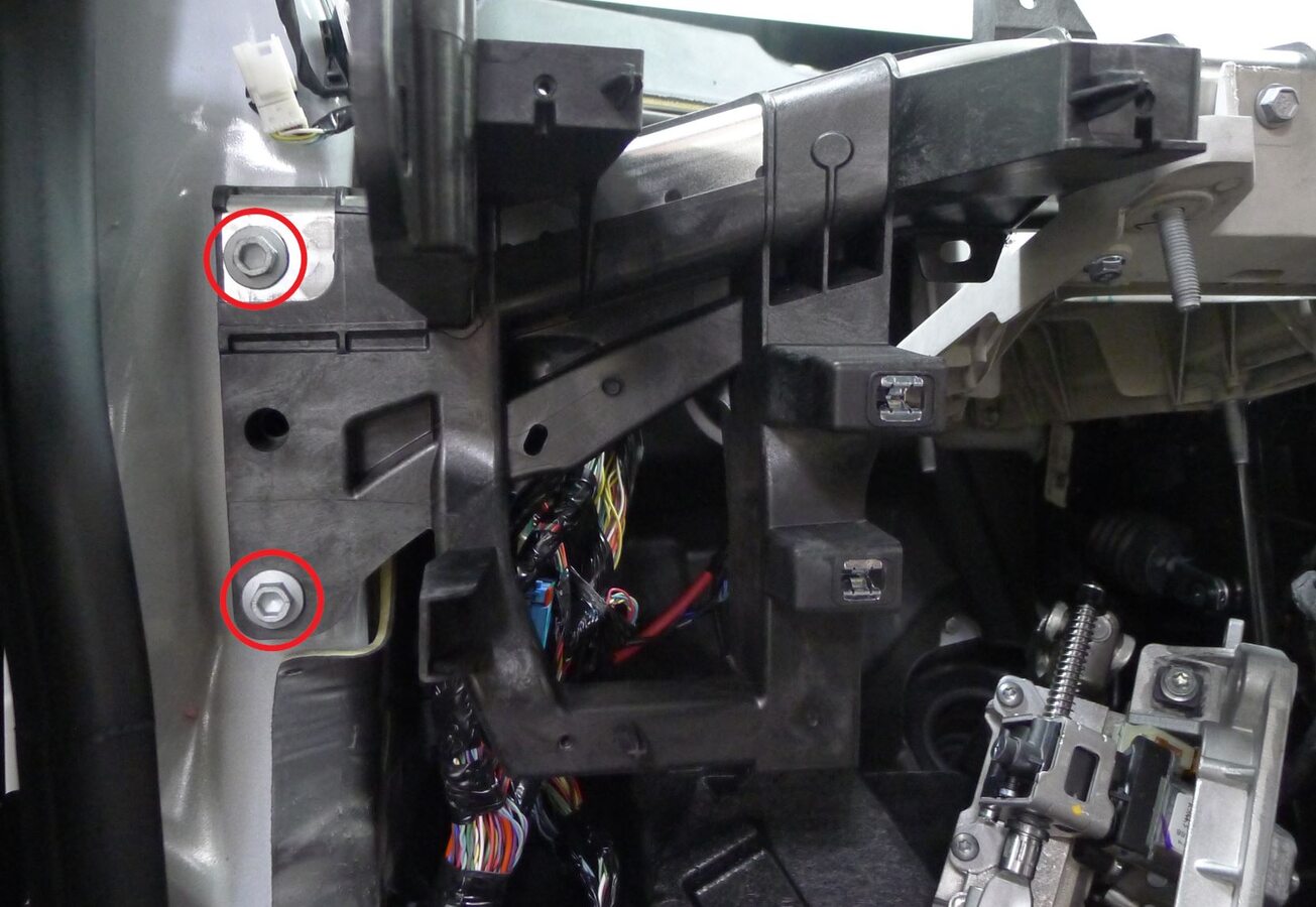
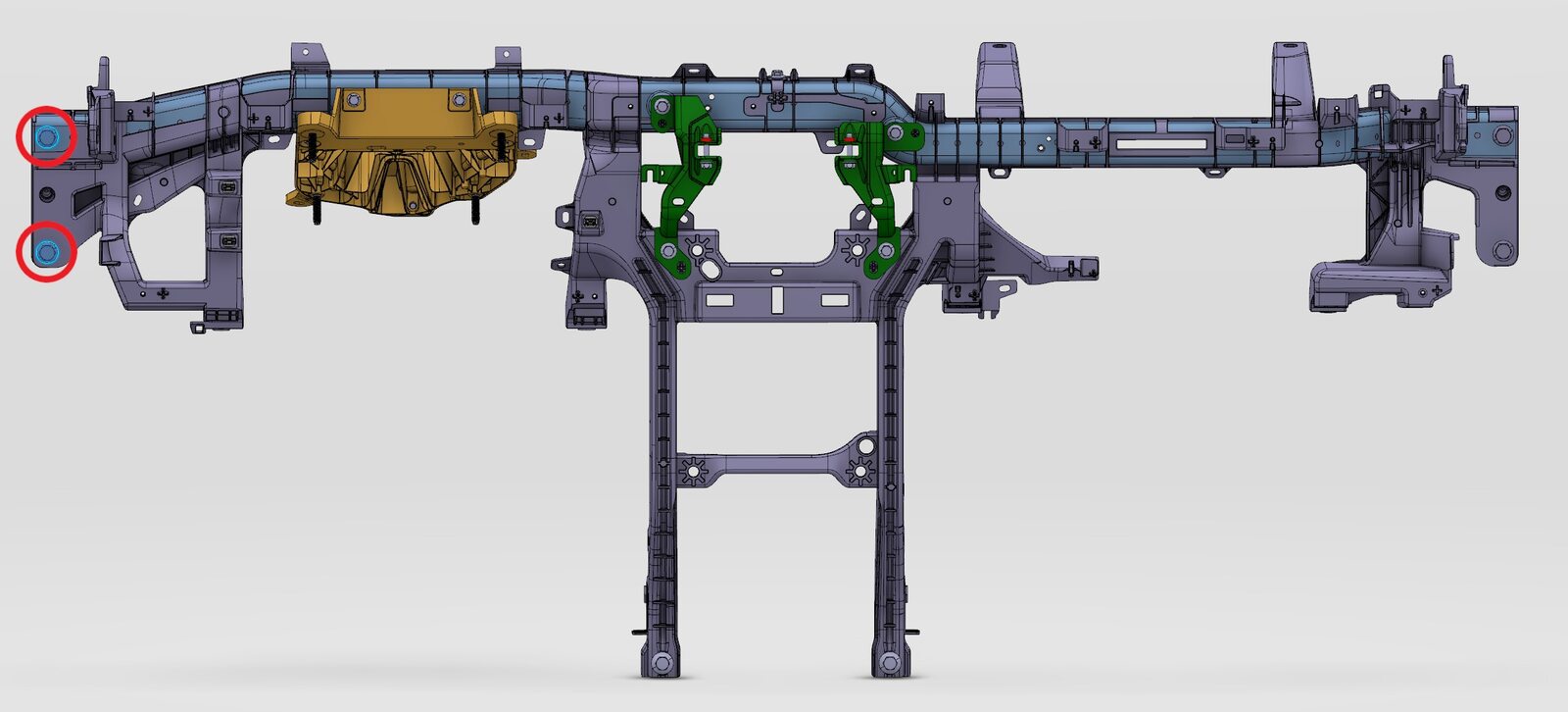
Release LH cross car beam assembly
注2x bolts, 13mm, 27 Nm
-
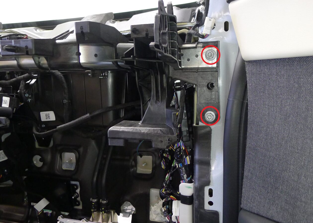
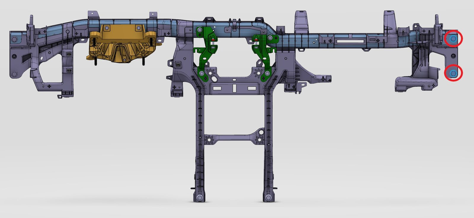
Release RH cross car beam assembly
注2x bolts, 13mm, 27 Nm
-
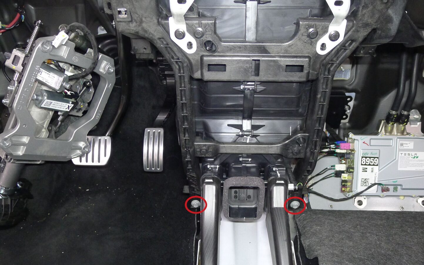
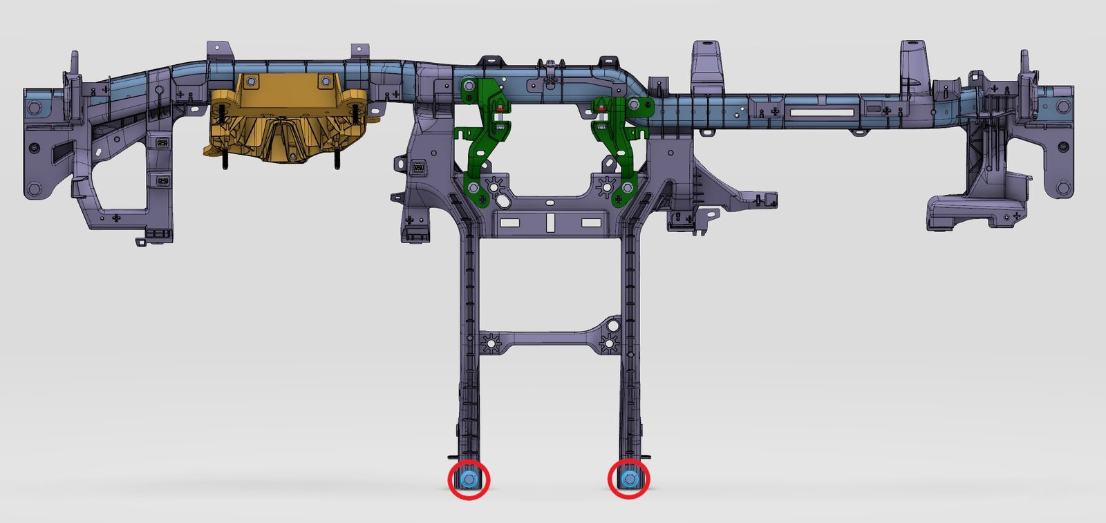
Release cross car beam assembly from toeboard bracket
注2x bolts, 13mm, 27 Nm
-
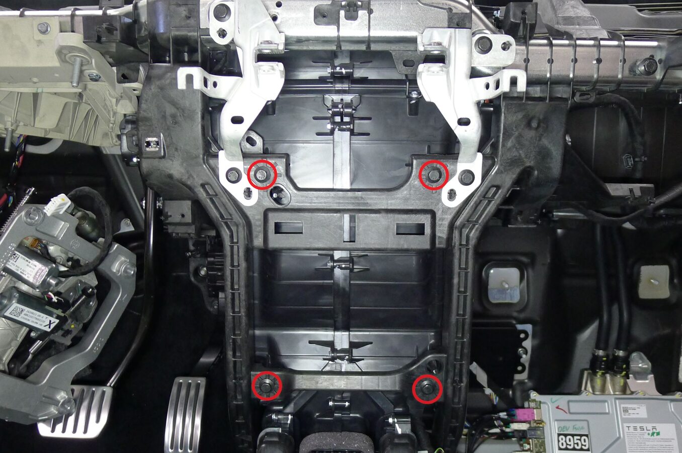
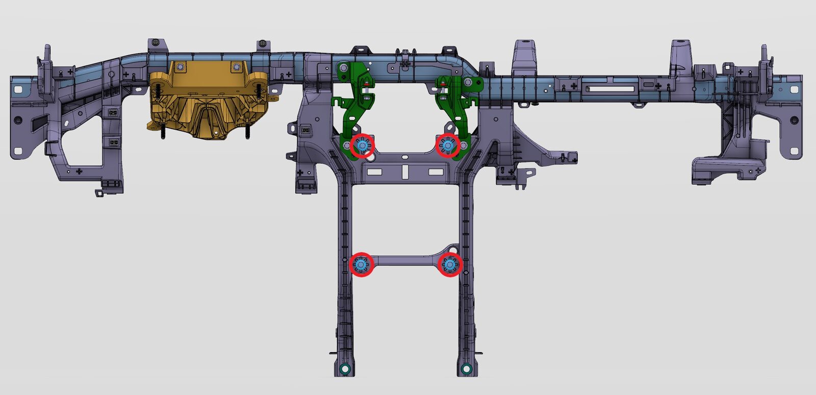
Release cross car beam assembly from HVAC unit
注4x bolts, 10mm, 8 Nm
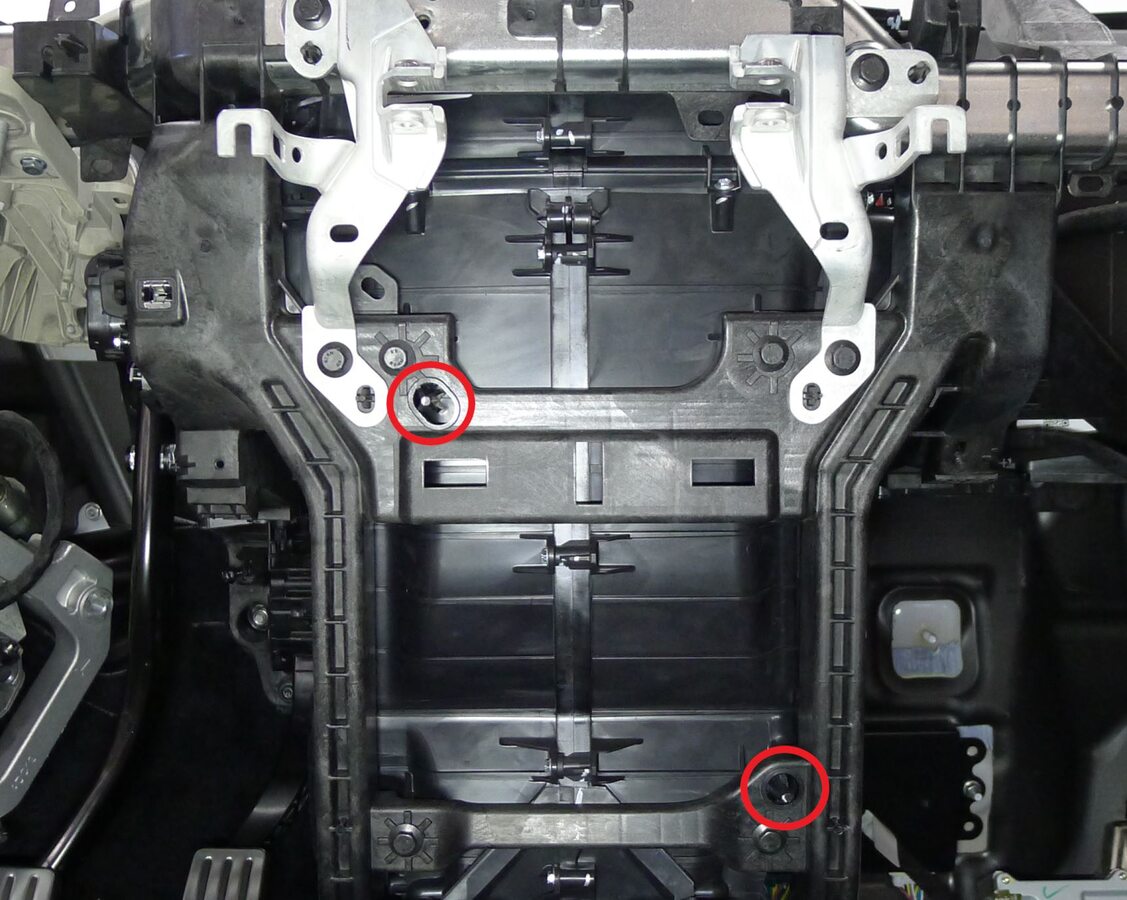
-
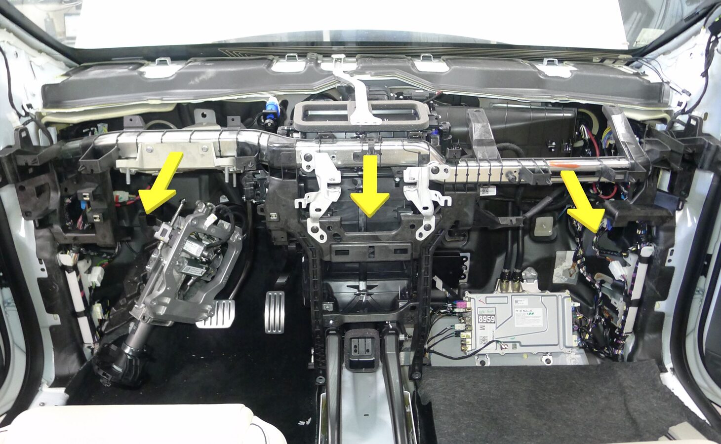
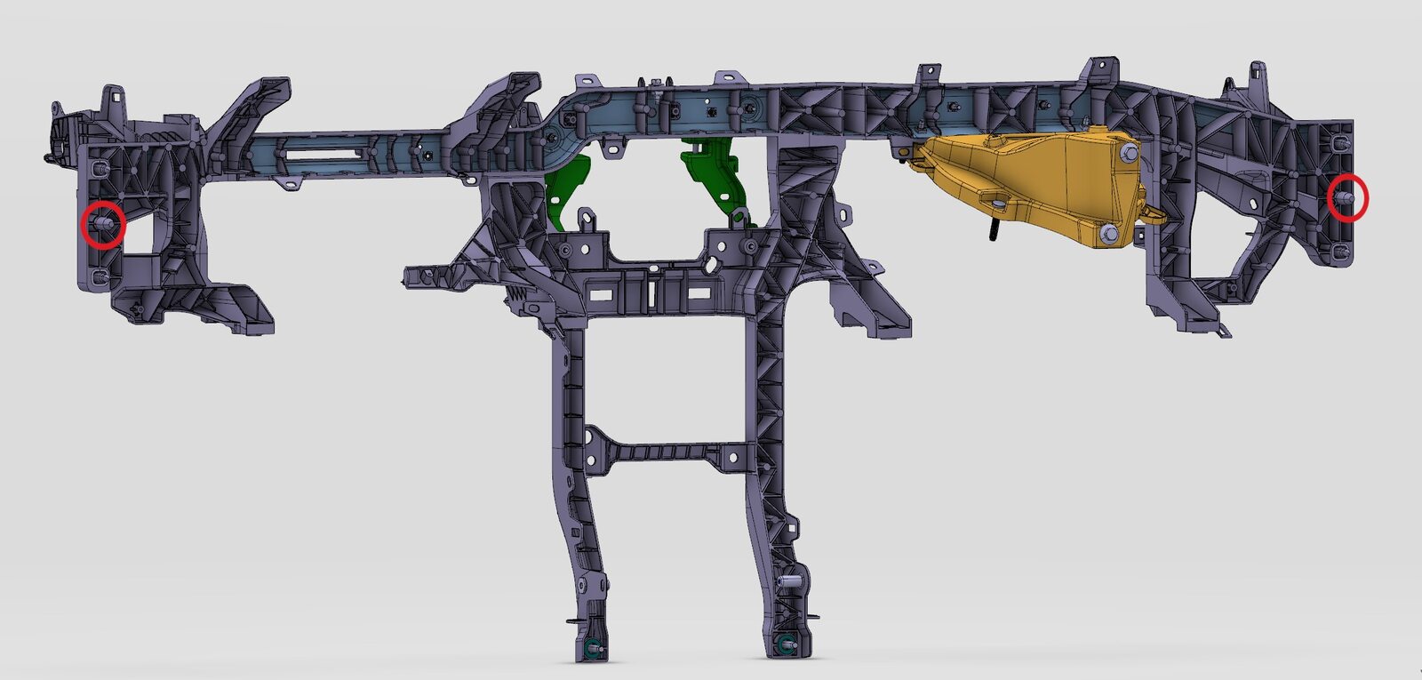
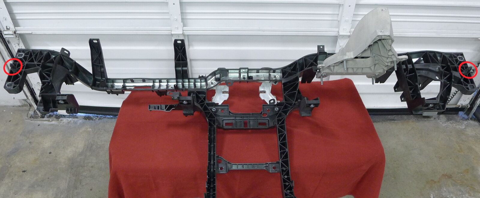
Remove cross car beam assembly from body and HVAC unit
注4x datums

-
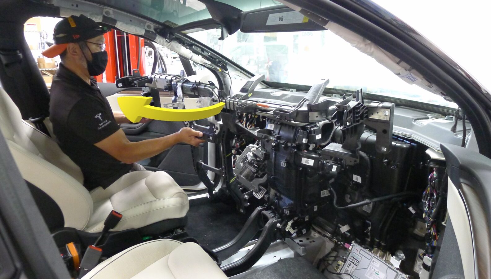
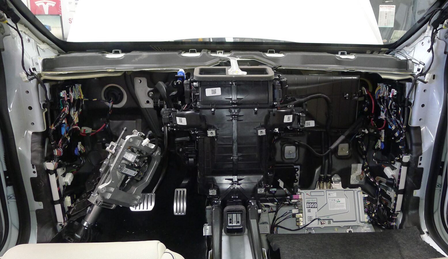
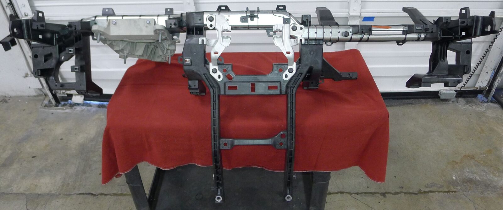
Remove cross car beam assembly from vehicle
注Avoid contact with seats and inner door panel, Recommend assistance as required
-
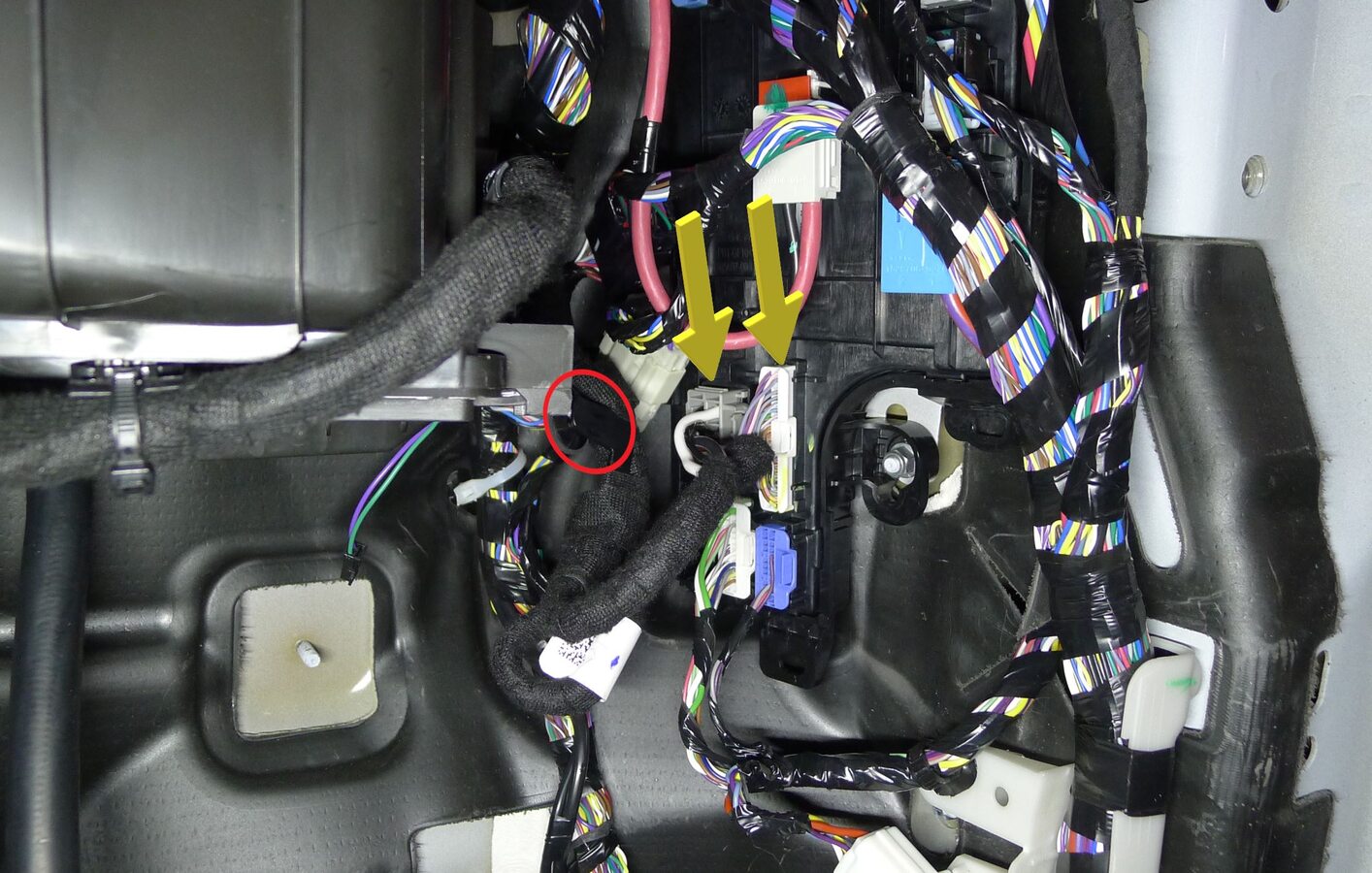
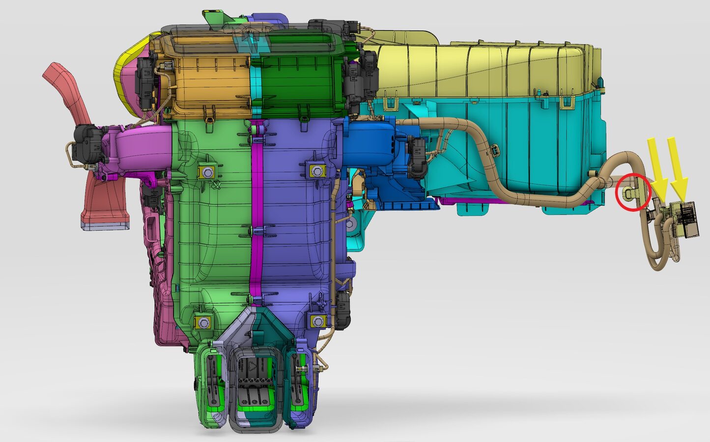
Release HVAC blower x059 connector and HVAC case x058 connector from right controller
注1x clip, 2x connectors
-
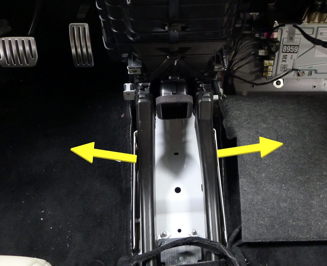
Release LH and RH rear vent ducts from HVAC assembly
-
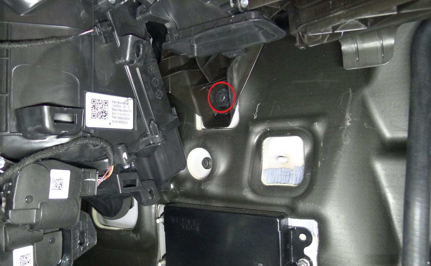
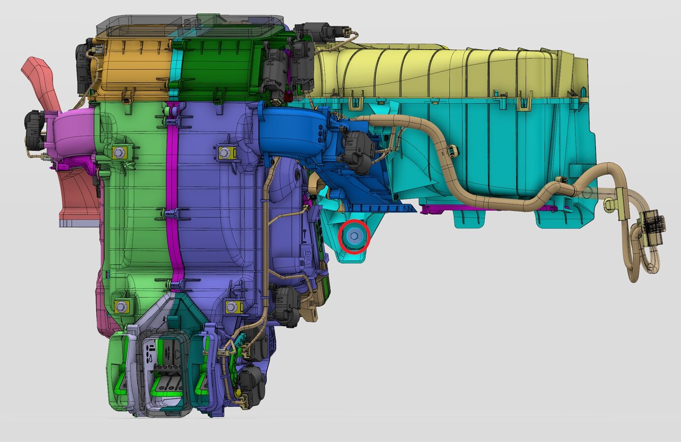
Release HVAC assembly from bulkhead
注1x bolt, 10mm, 8 Nm
-
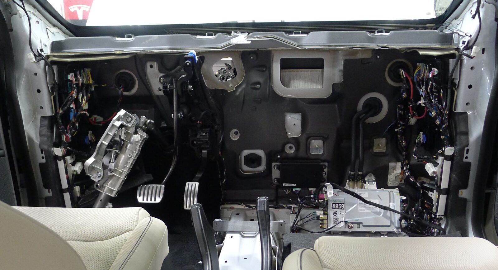
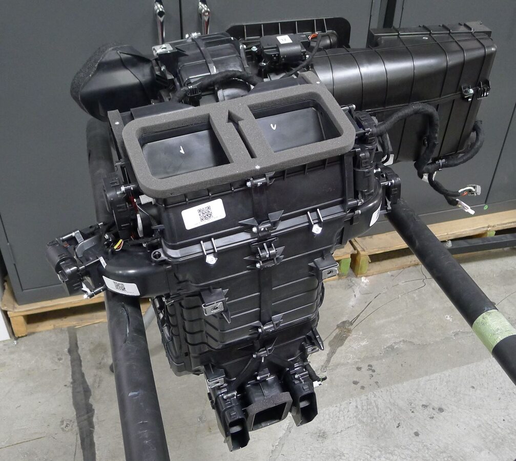
Remove HVAC assembly from vehicle
注Remove HVAC assembly towards rear of vehicle, Rotate counter clockwise and remove out of passenger front door, Recommend assistance

-
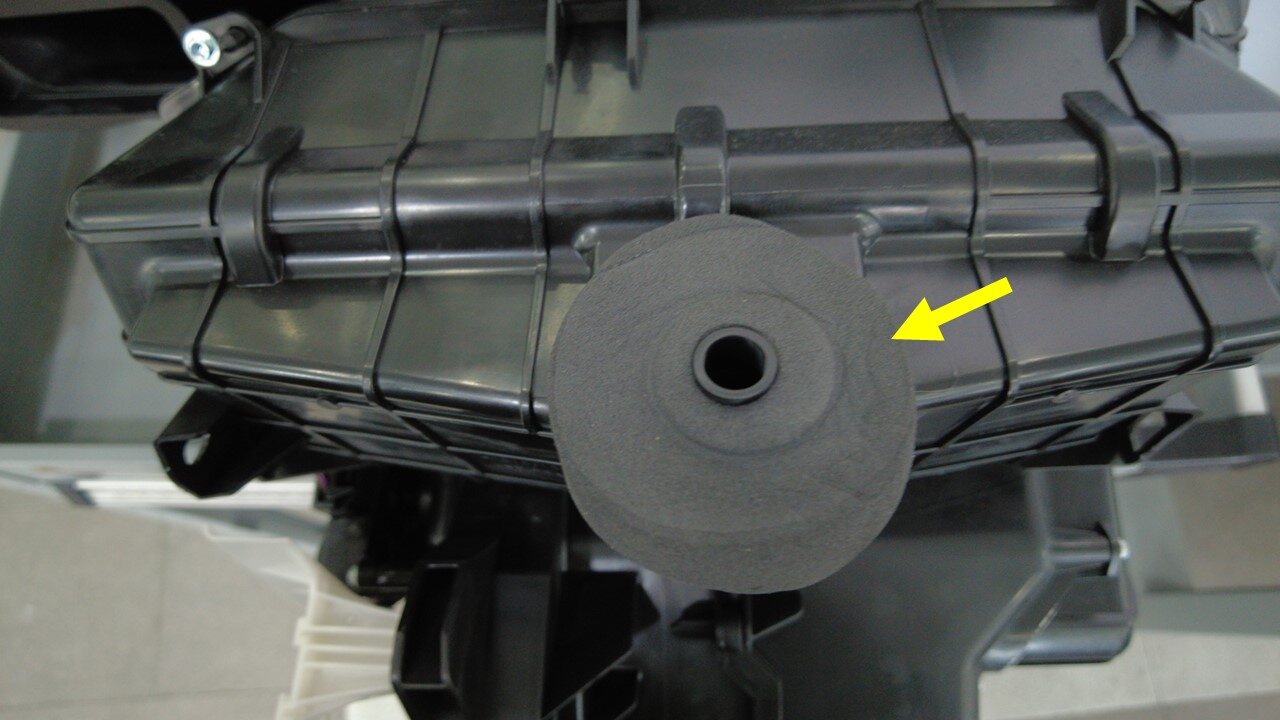
Remove HVAC Sump Seal from HVAC assembly
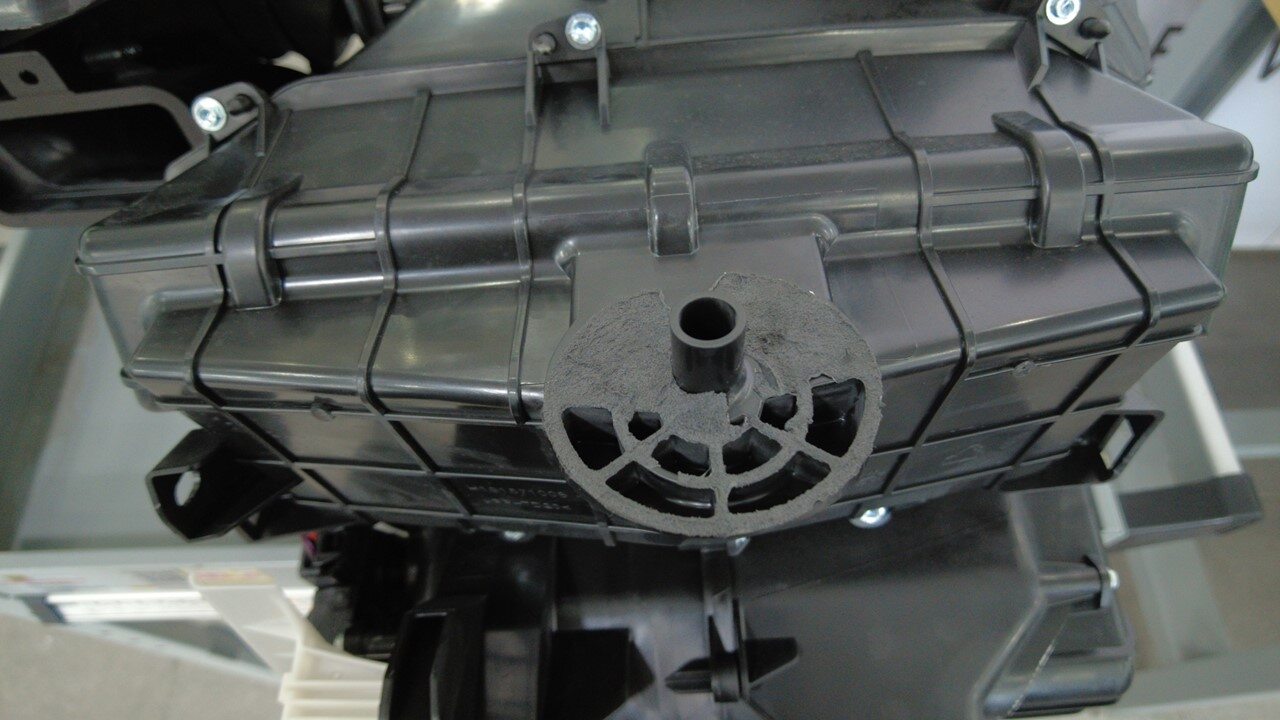
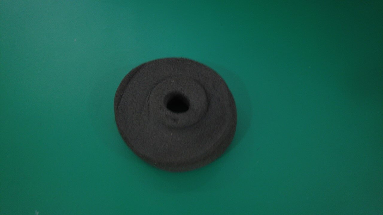
-
Clean old adhesive residue from HVAC assembly
注Allow 1 minute for IPA to dry
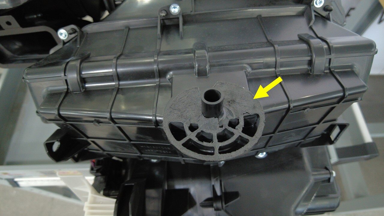
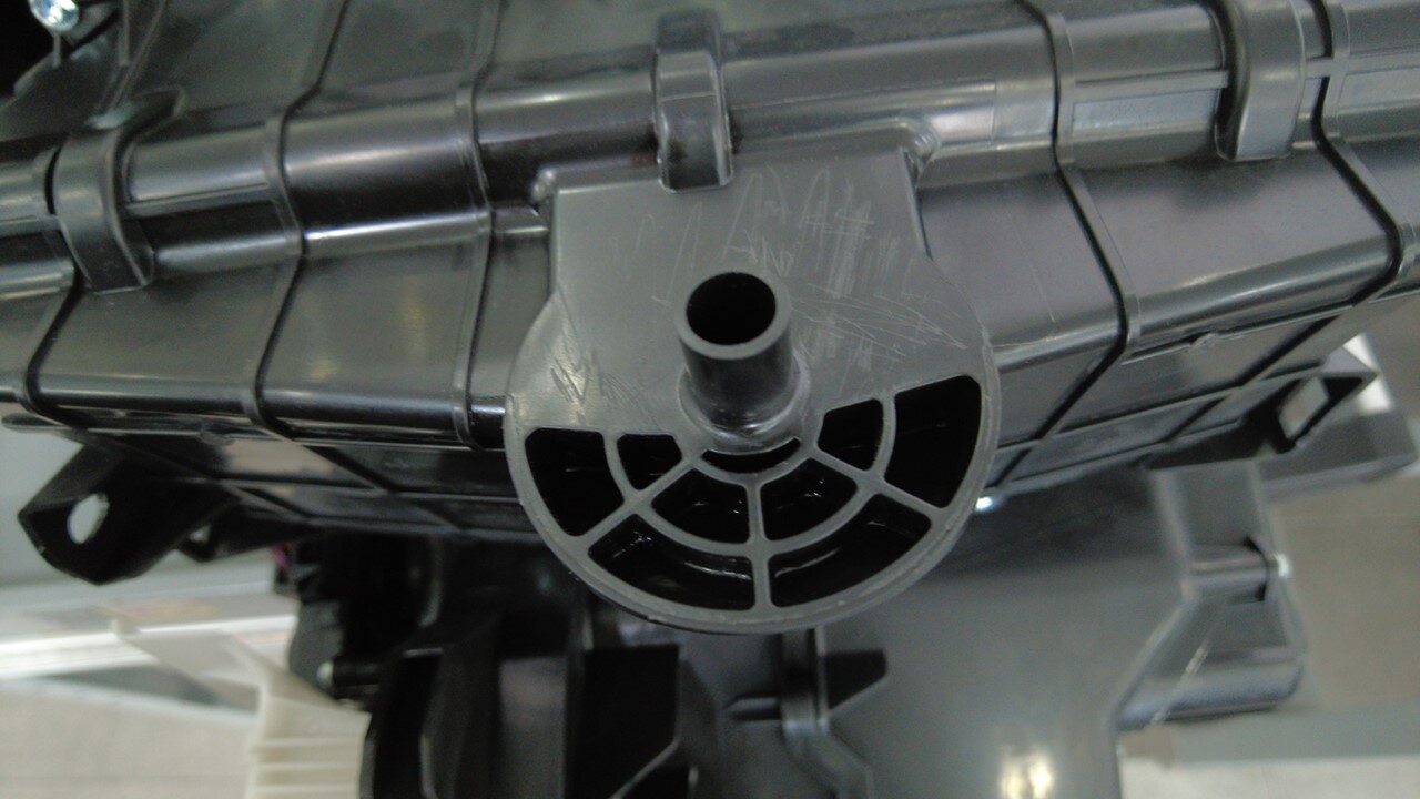
-
Peel off film from HVAC Sump Seal
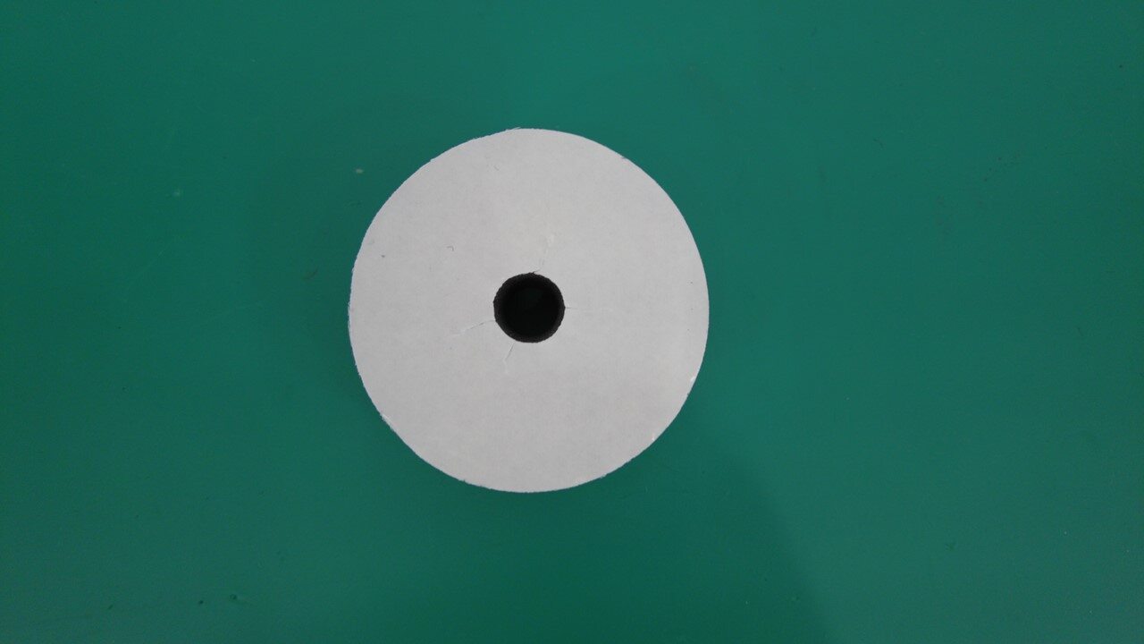
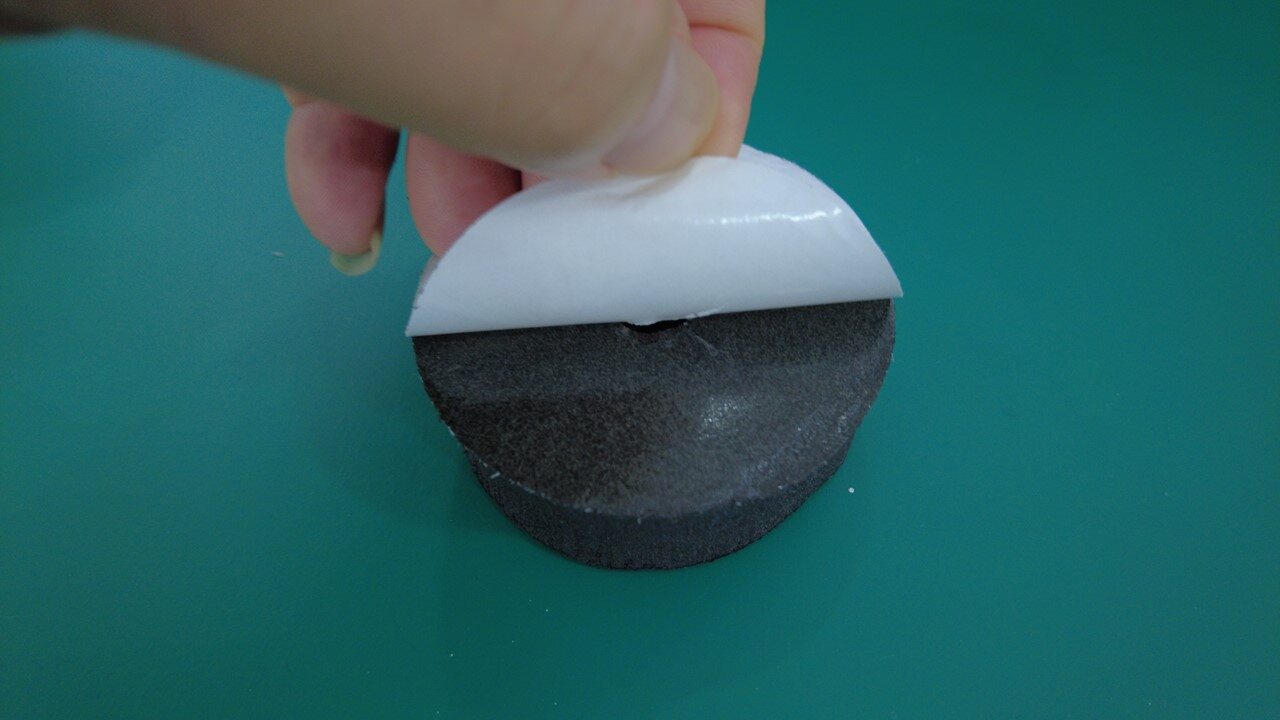
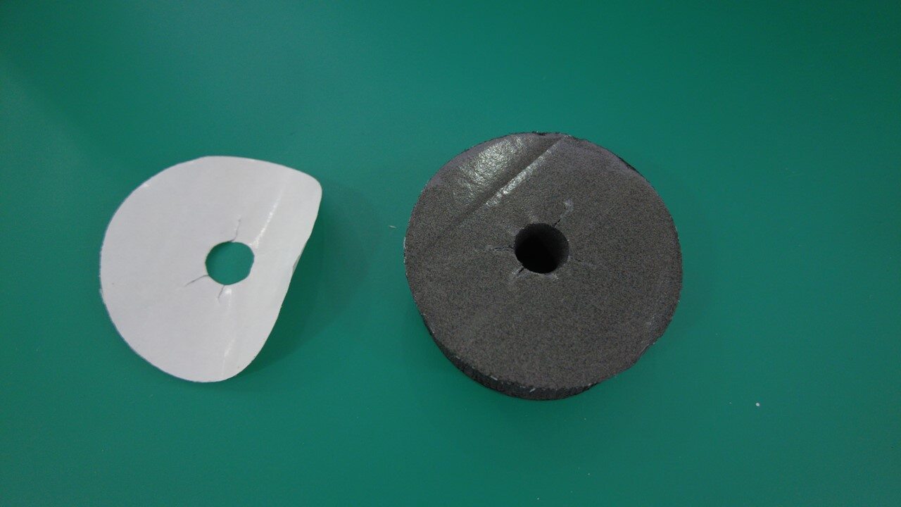
-
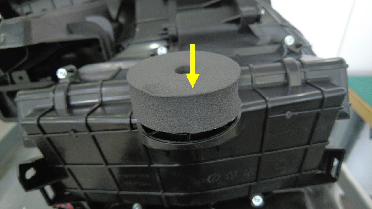
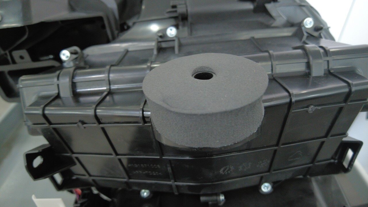
Install HVAC Sump Seal to HVAC assembly
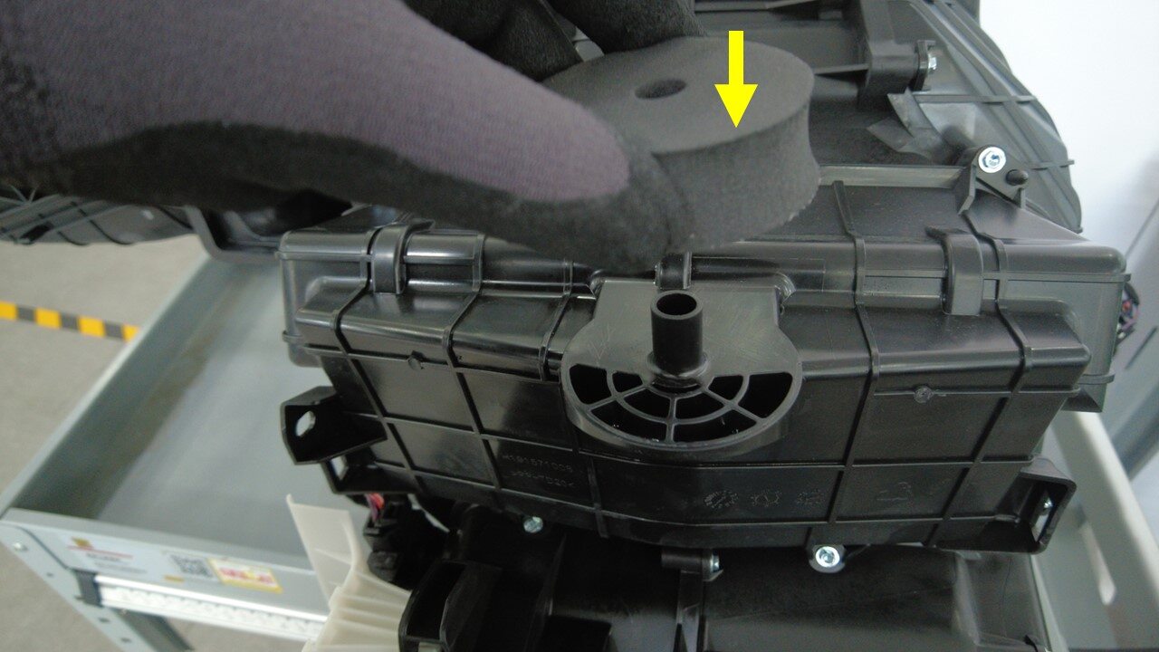
-
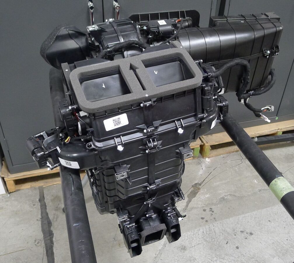
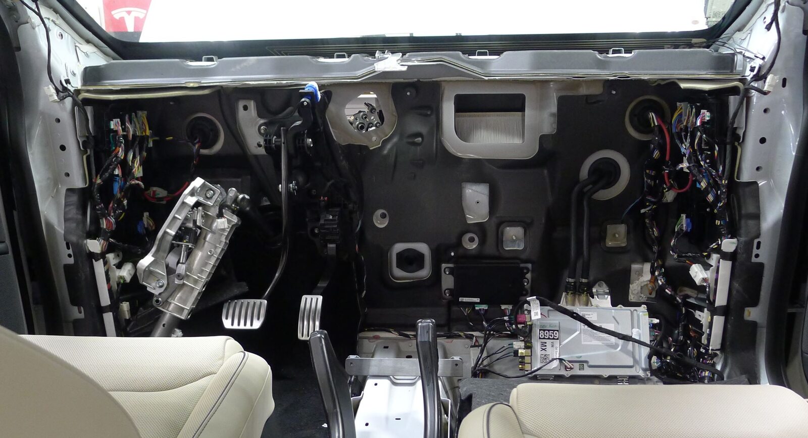
Install HVAC assembly to vehicle
注Install front of HVAC assembly through passenger front door, Rotate counter clockwise and install towards front of vehicle

-
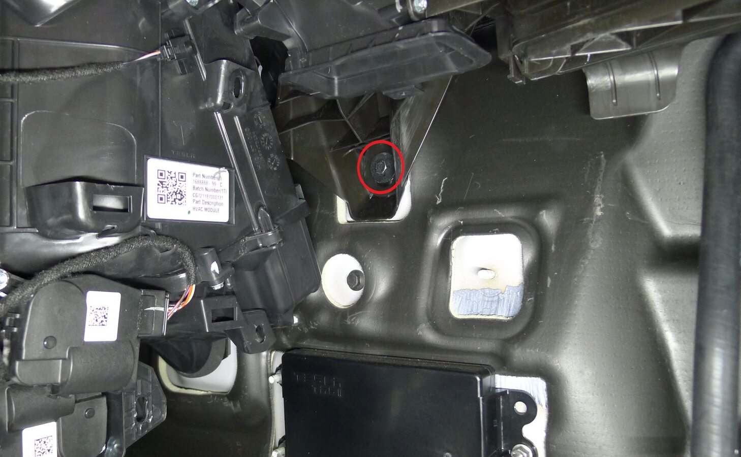
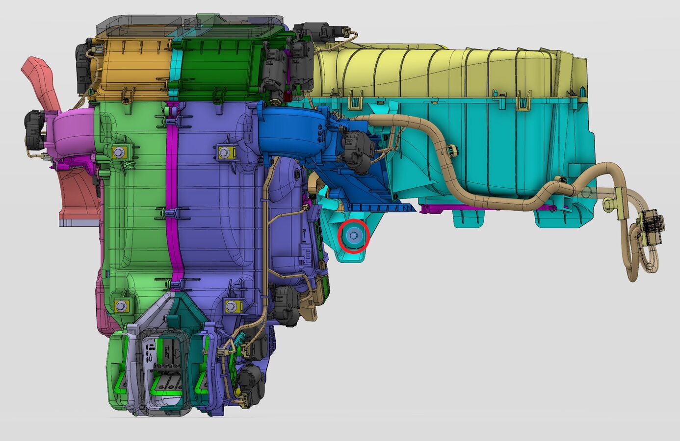
Secure HVAC assembly to bulkhead
注1x bolt, 10mm, 8 Nm
-
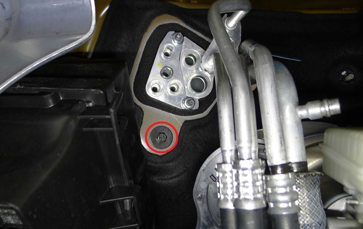
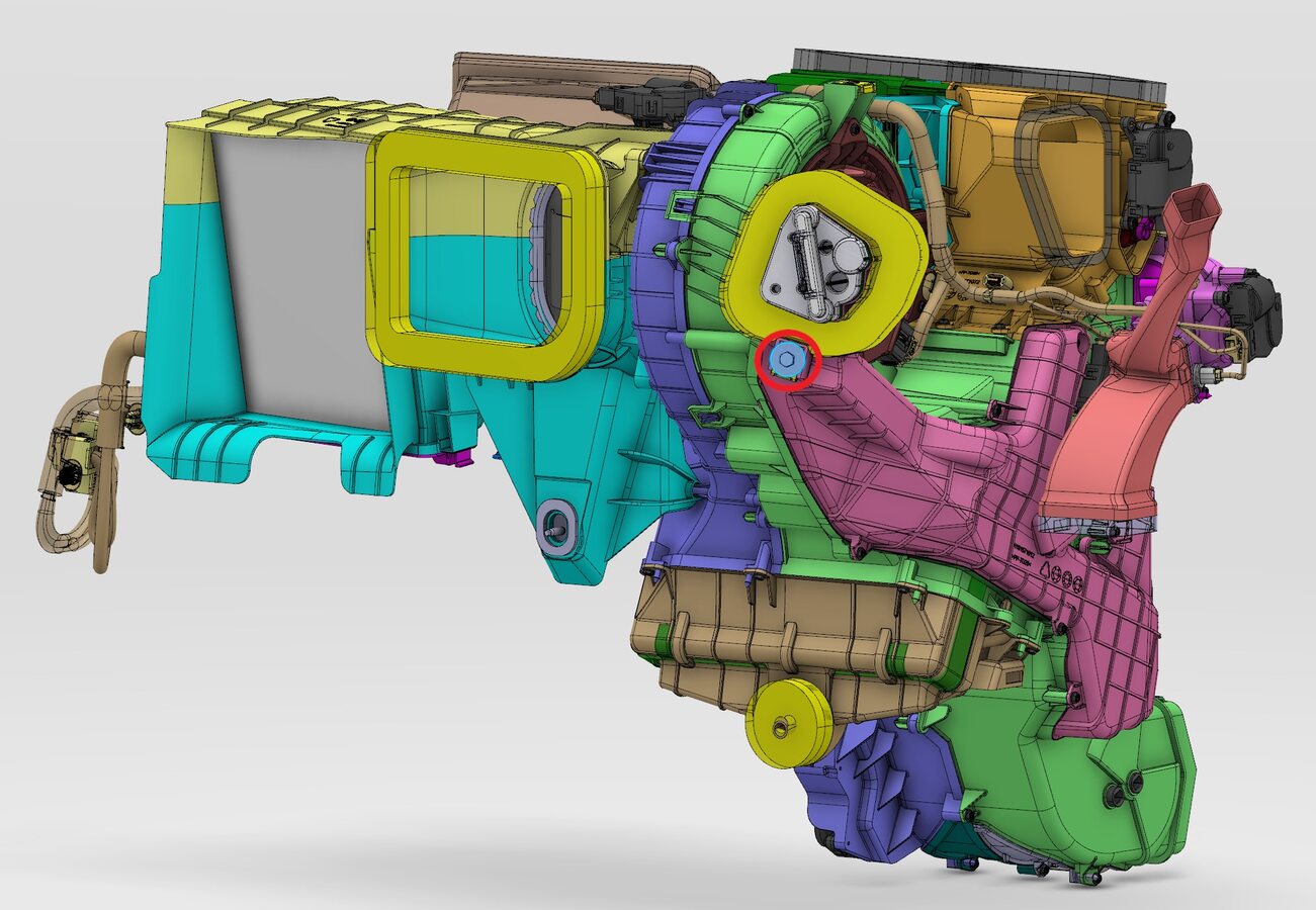
Secure HVAC assembly bolt at bulkhead
注1x bolt, 10mm, 8 Nm
-
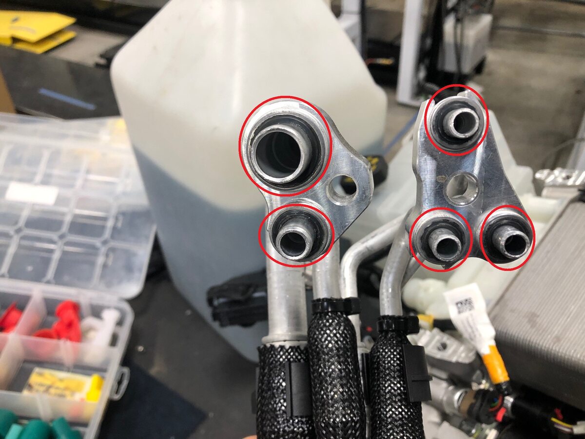
Replace the seal washers to the Penta HVAC line on the HVAC side
注5x seal washers, Lube seal washers with ND-11 oil
-
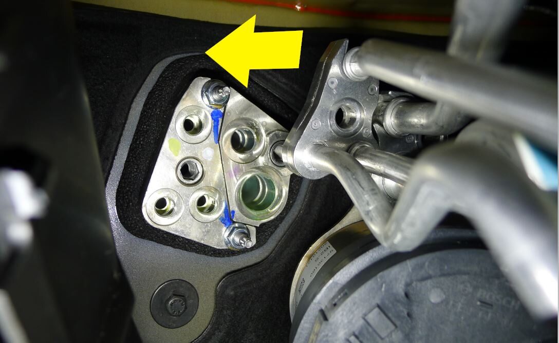
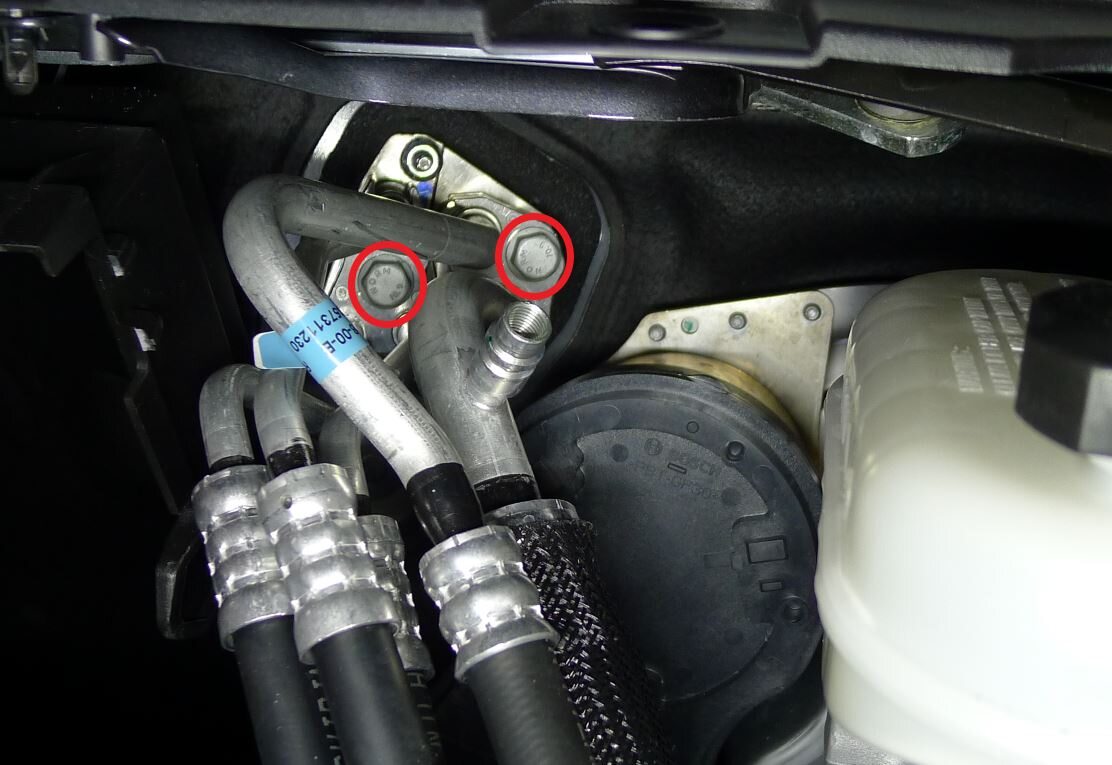
Install Penta HVAC line to HVAC assembly
注2x bolts, 13mm, 22 Nm
-
Connect AC hoses to vehicle
-
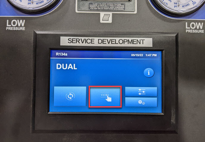
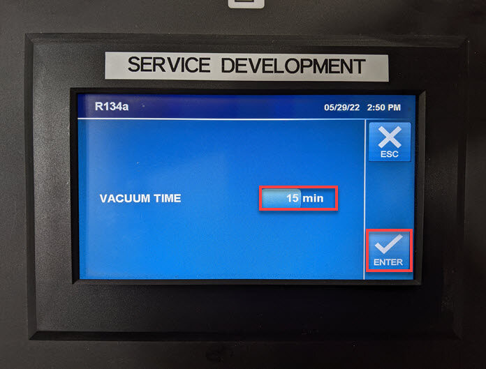
Perform AC vacuum and run leak test
注Touch time only: Menu > Vacuum > Type 15 min > Select Enter

-
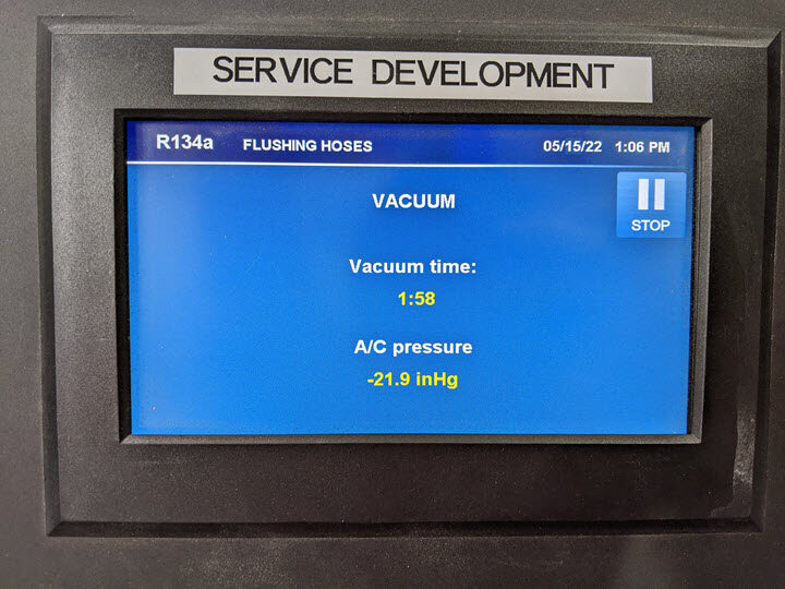
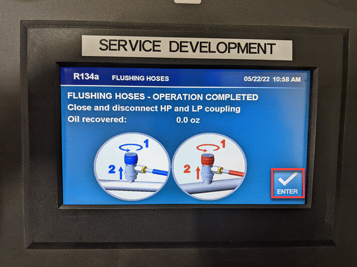
Perform AC vacuum and run leak test
注Run time only: Set vacuum time to 15 minutes and leak test to ON, Machine will chime once process is complete, Vehicle may be left unattended, Verify leak test passed before continuing
-
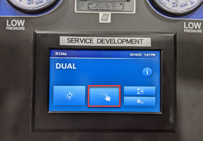
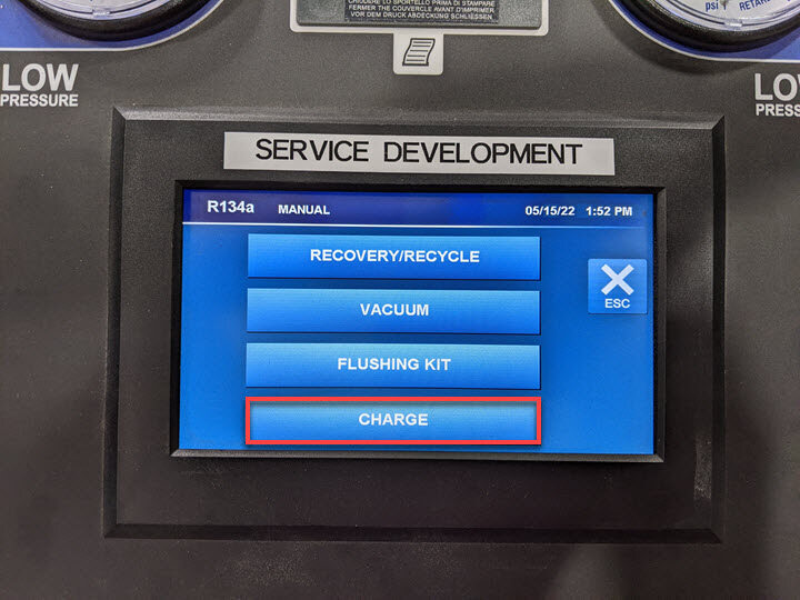
Perform AC charge
注Touch time: Enter refrigerant and oil amount noted at AC recovery, Settings should match notes, Select Both Sides for charge, Select ND-11 MSX using bottle icon, Machine will chime once process is complete, Vehicle may be left unattended, If desired use the Dye Inject option to inject leak detection dye
-
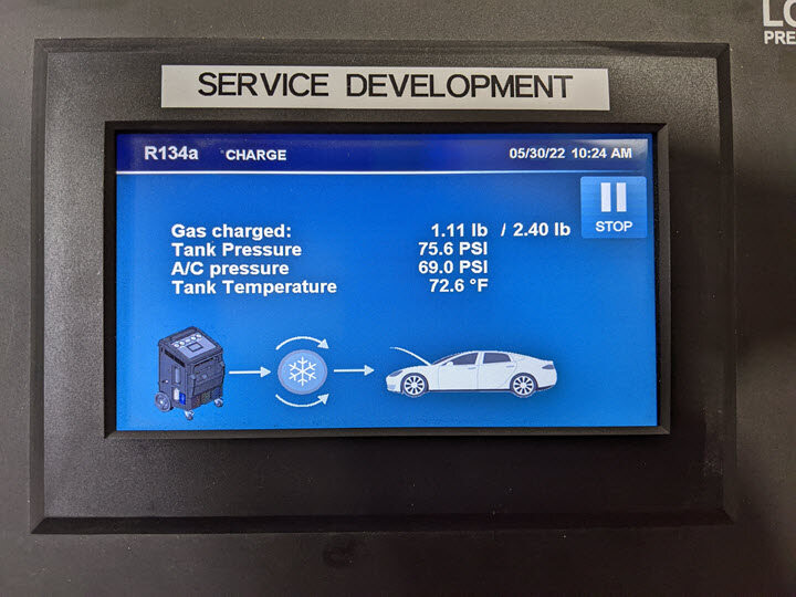
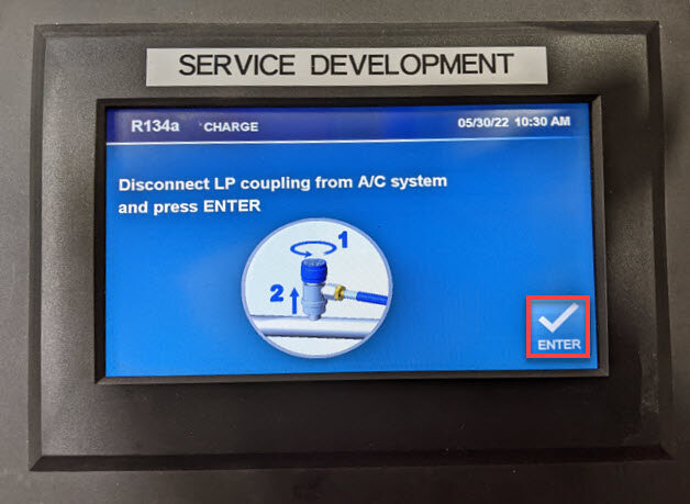
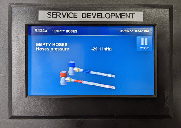
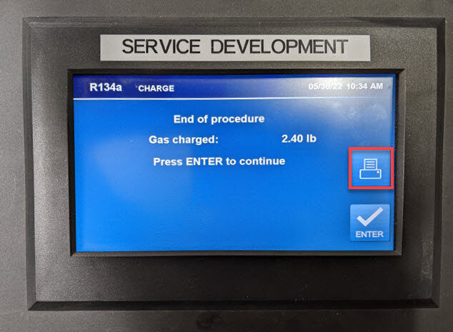
Perform AC charge
注Run time - Enter refrigerant and oil amount noted at AC recovery, Settings should match notes, Select Both Sides for charge, Select ND-11 MSX using bottle icon, Machine will chime once process is complete, Vehicle may be left unattended, If desired use the Dye Inject option to inject leak detection dye
-
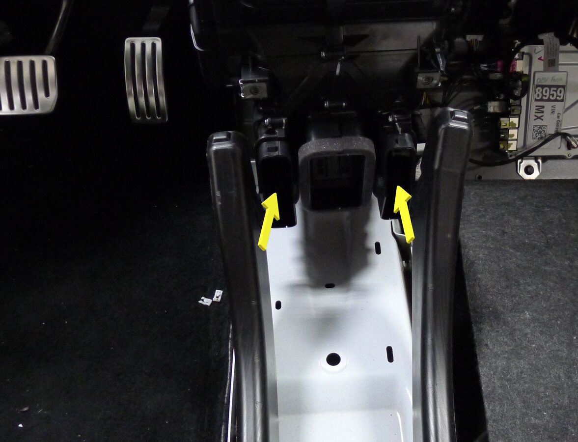
Secure LH and RH rear vent ducts to HVAC assembly
-
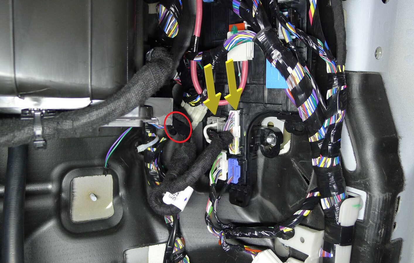
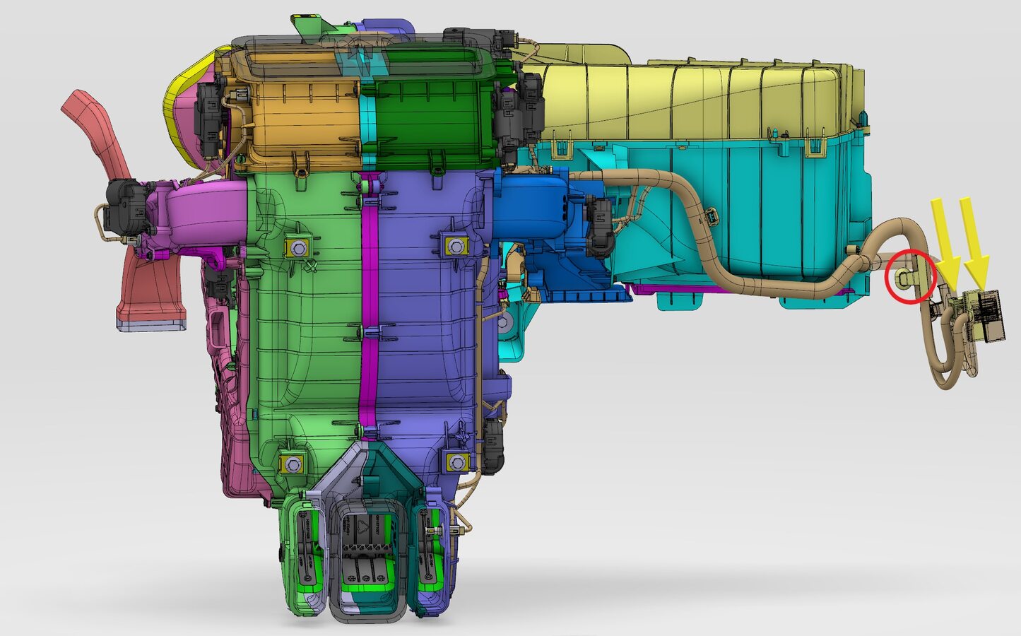
Secure HVAC blower x059 connector and HVAC case x058 connector to right controller
注1x clip, 2x connectors
-
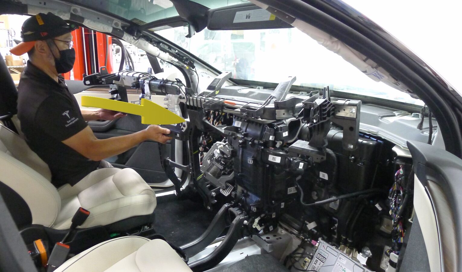
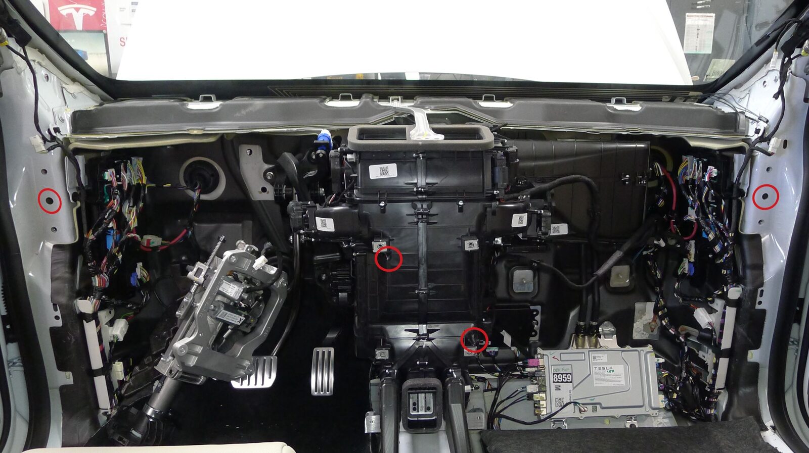
Install cross car beam assembly into vehicle
注4x datums, Avoid contact with seats and inner door panel, Recommend assistance as required, Align datums before fully engaging with HVAC assembly
-
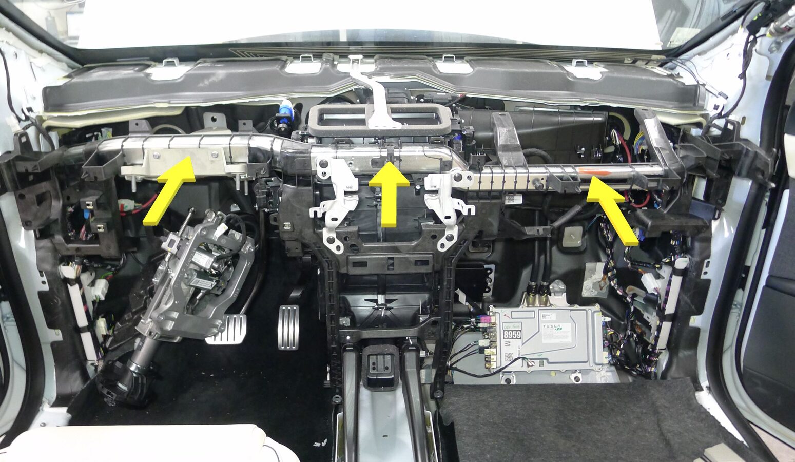
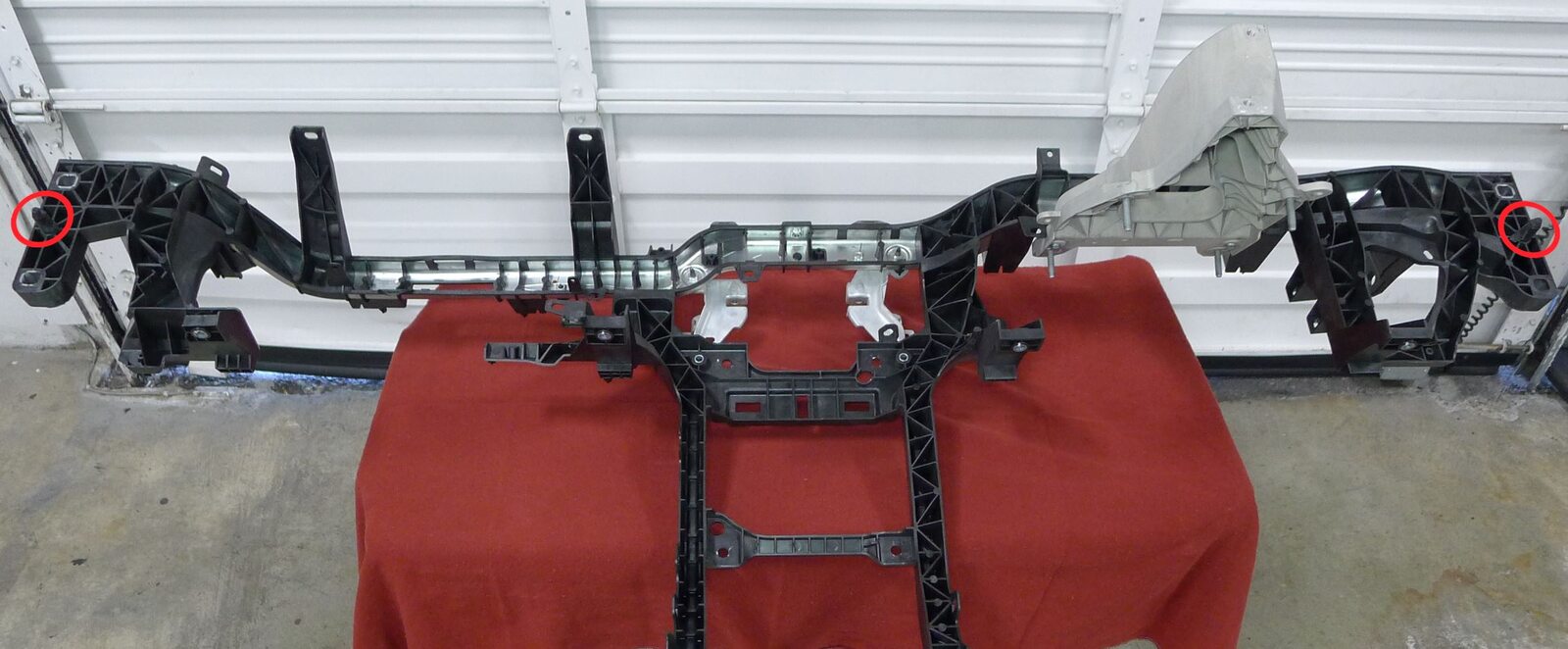
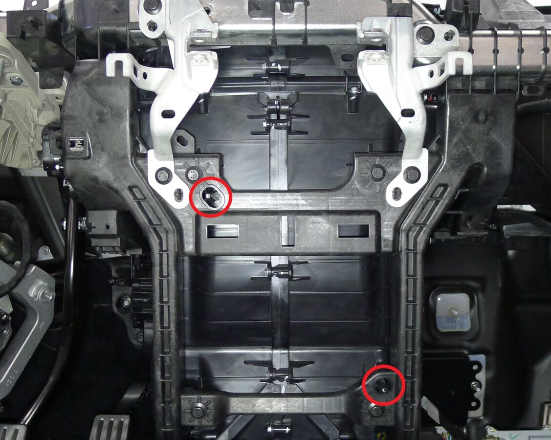
Engage cross car beam assembly to body and HVAC unit
注4x datums
-
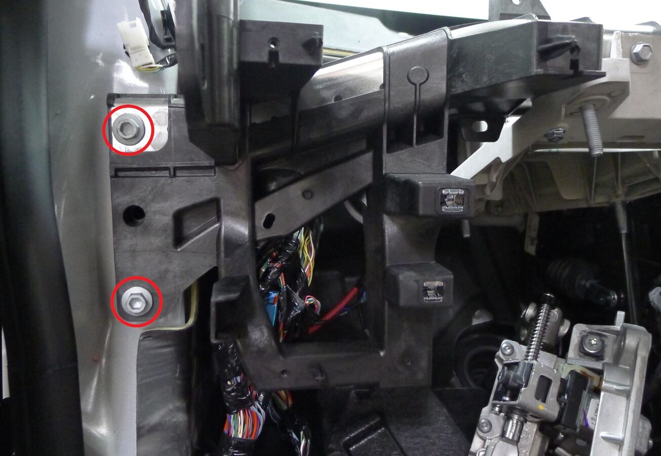
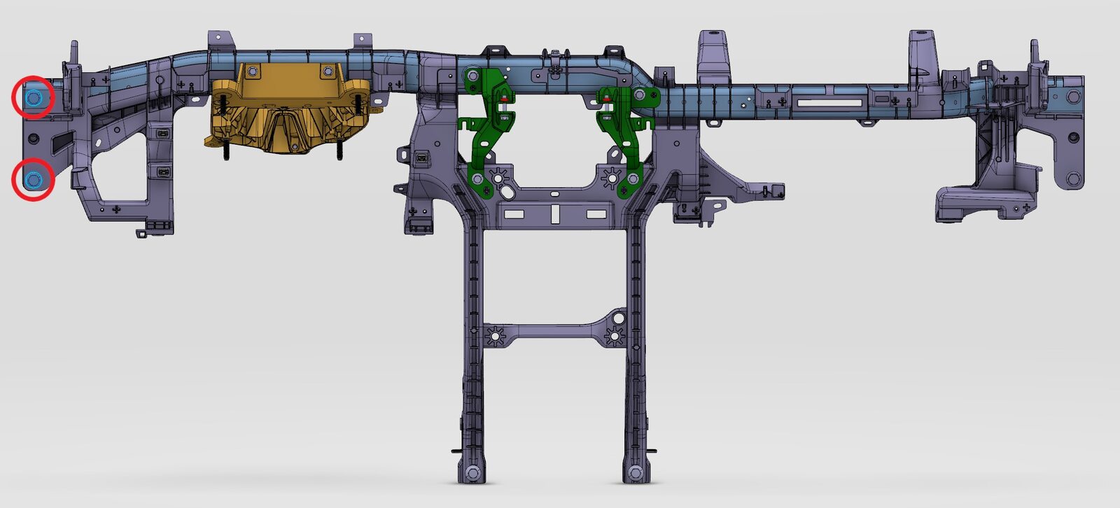
Secure LH cross car beam assembly
注2x bolts, 13mm, 27 Nm
-
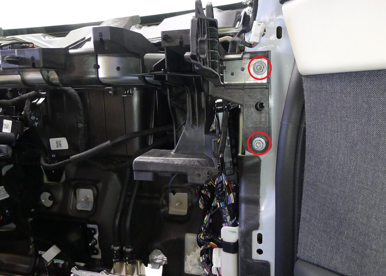
Secure RH cross car beam assembly
注2x bolts, 13mm, 27 Nm
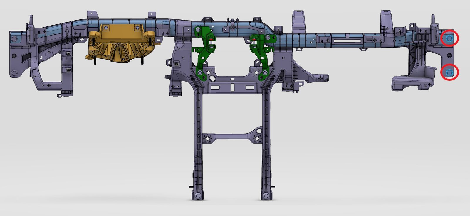
-
Secure cross car beam assembly to toeboard bracket
注2x bolts, 13mm, 27 Nm
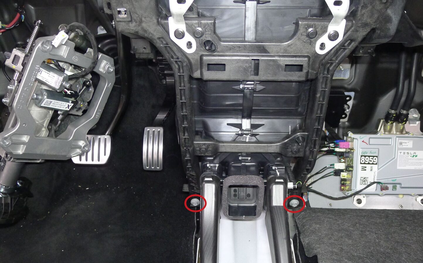
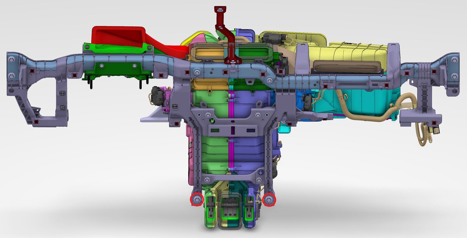
-
Secure cross car beam assembly to HVAC unit
注4x bolts, 10mm, 8 Nm
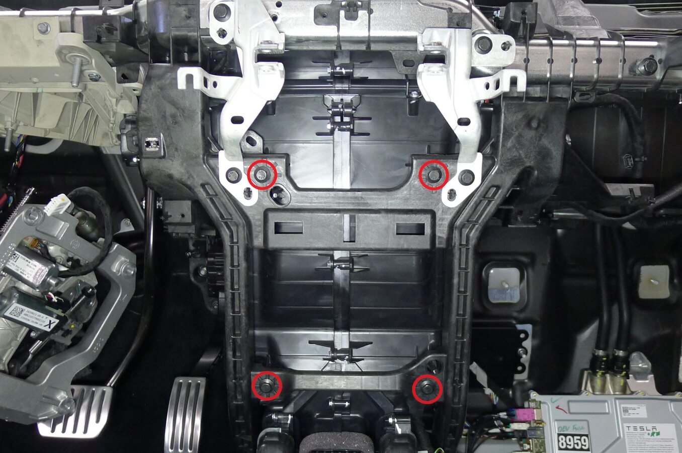
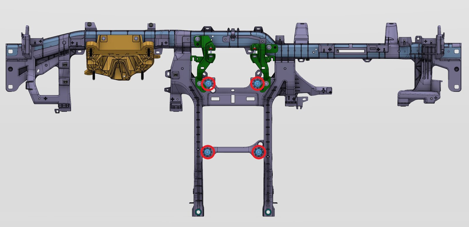
-
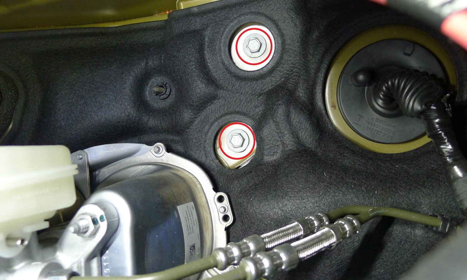
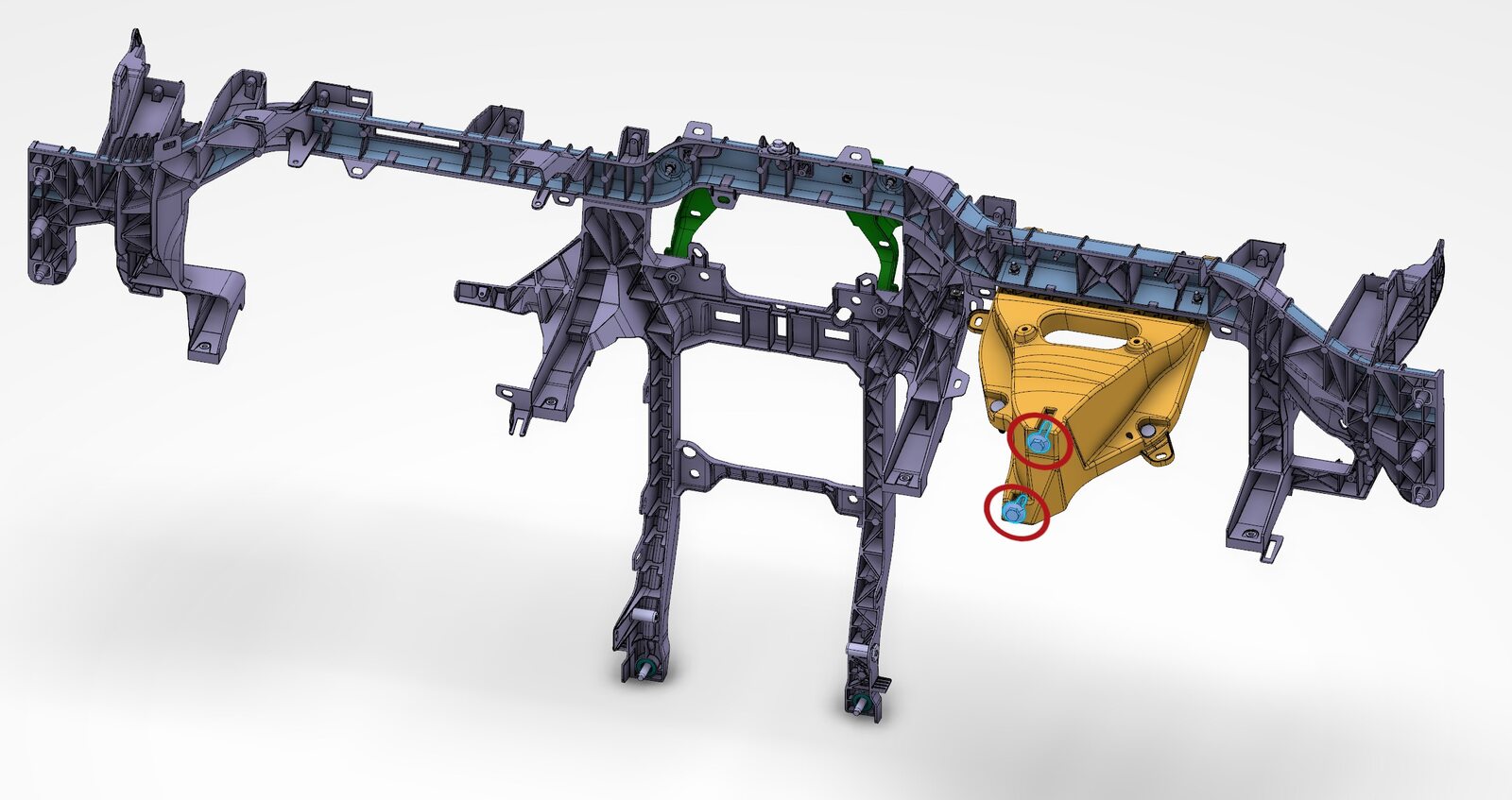
Secure upper steering column bracket IP carrier bolts at bulkhead
注2x bolts, 13mm, 27 Nm
-
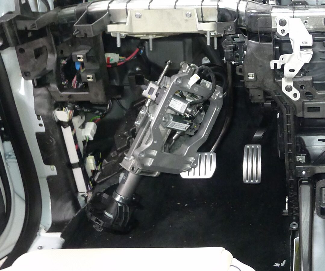
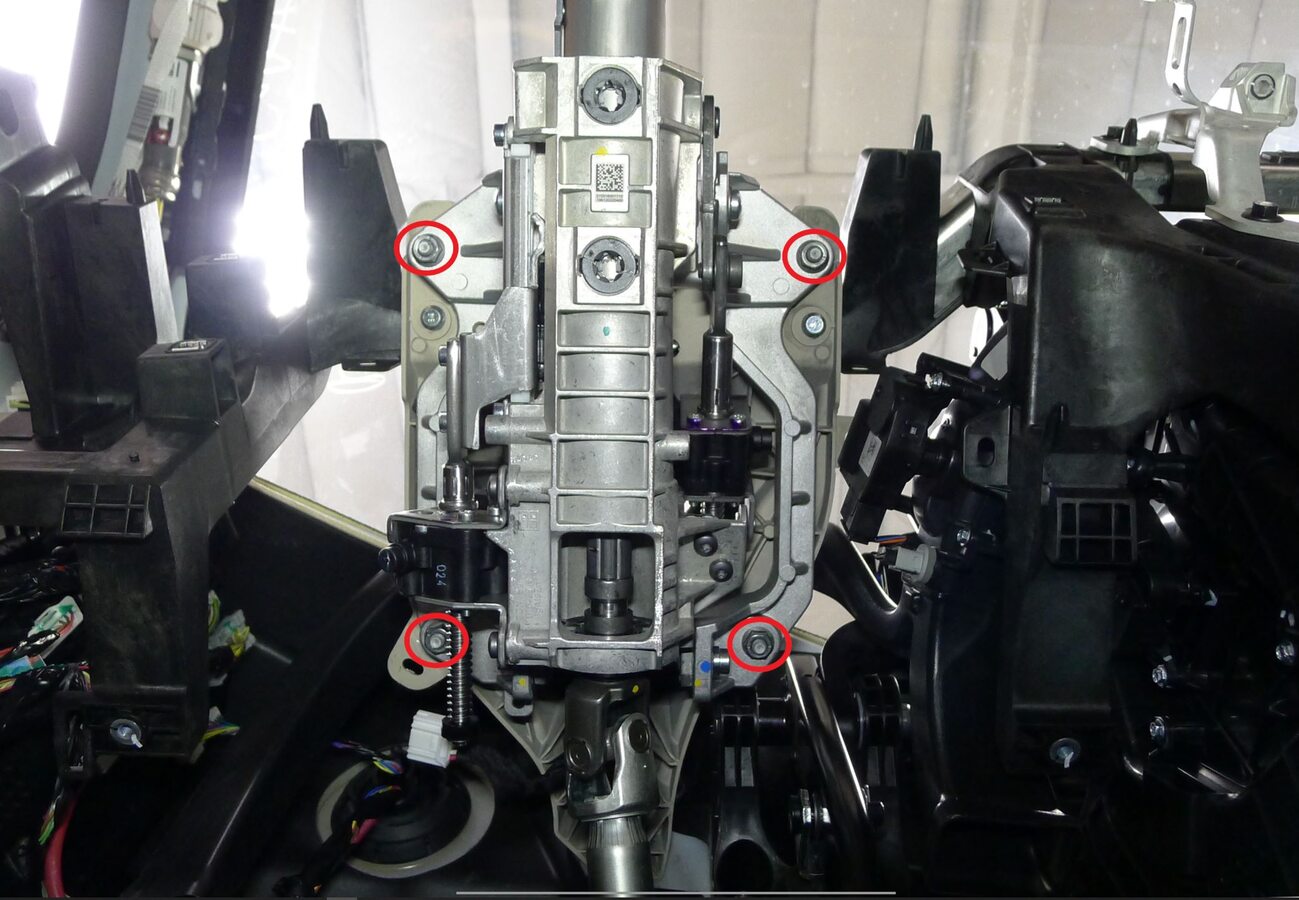
Secure upper steering column to steering column bracket
注4x nuts, 13mm, 15 Nm
-
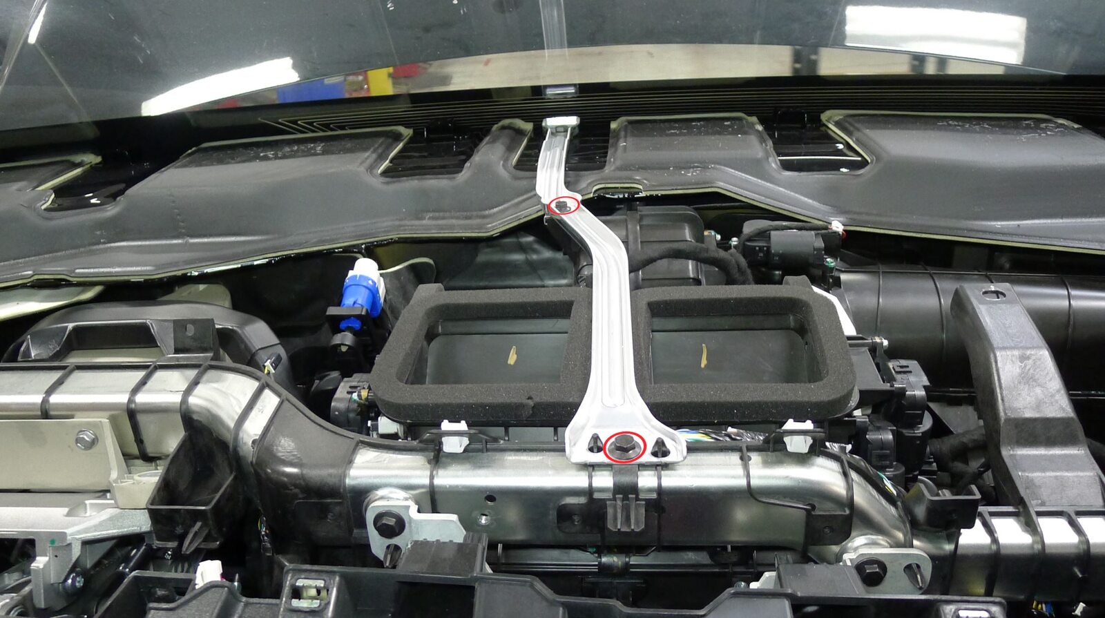
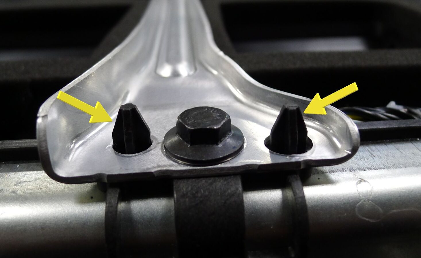
Secure IP cowl link
注2x bolts, 10mm, 6 Nm, 2x datums
-
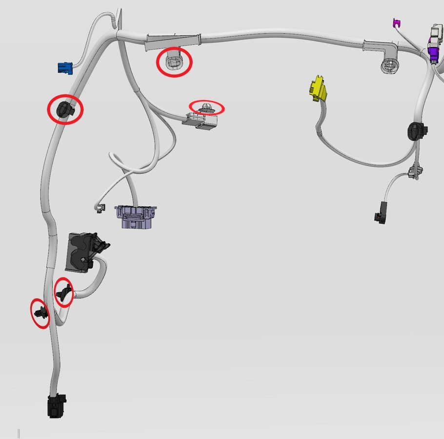
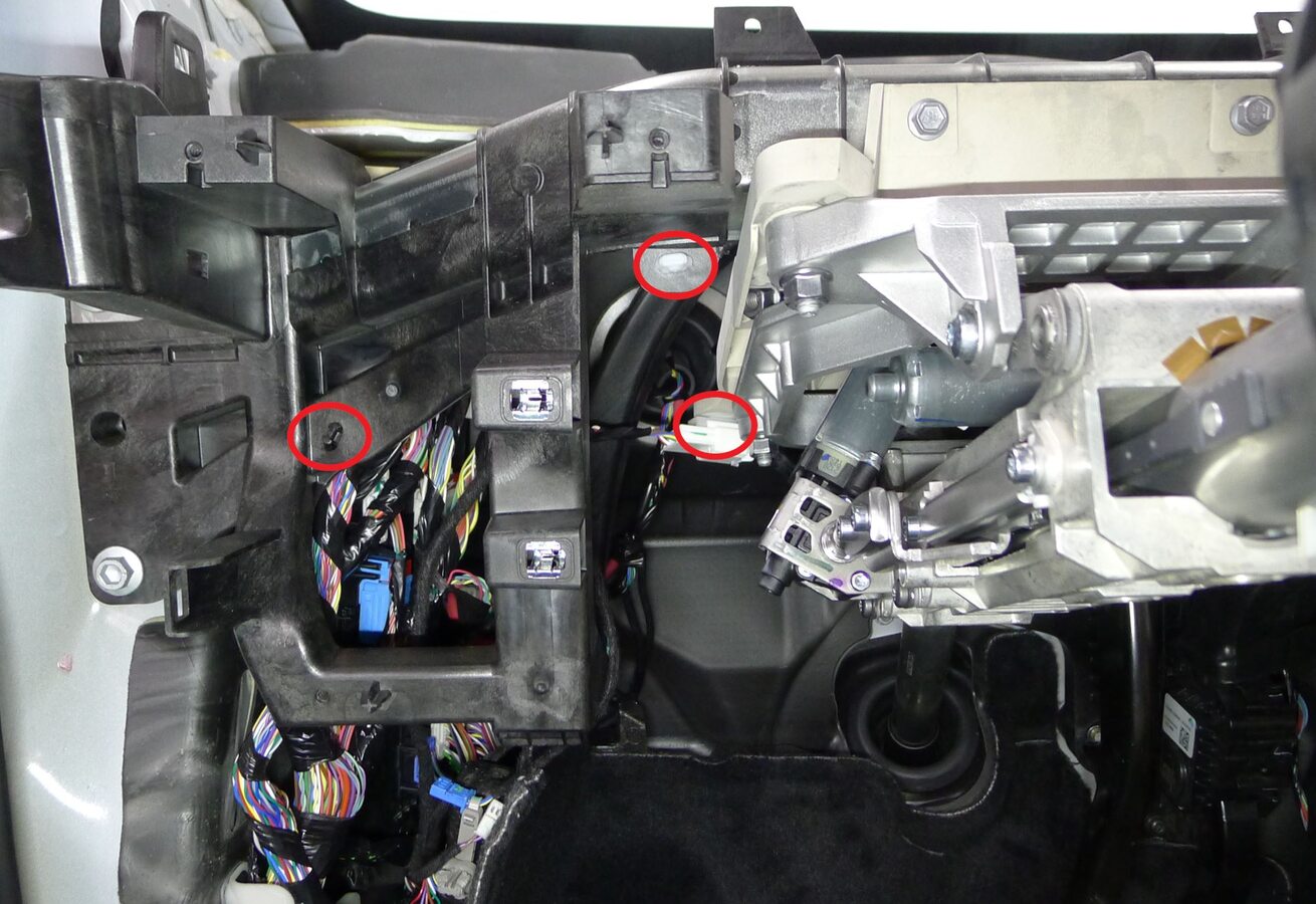
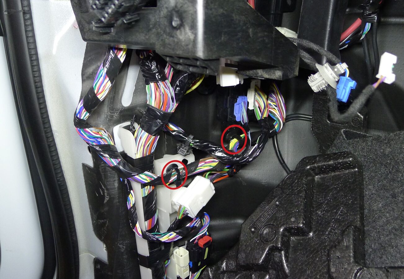
Secure IP harness to LH IP carrier
注5x clips
-
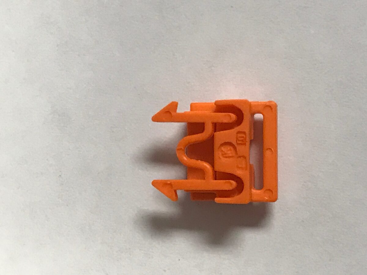
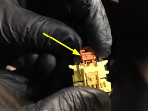
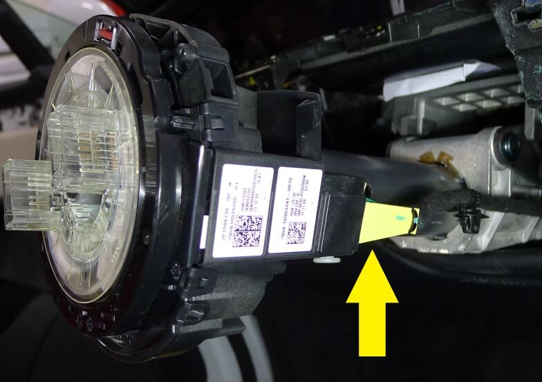
Connect steering column control module assembly connector
注1x connector, Install new orange retaining clip to connector then install SCCM connector, Perform push-pull-push to make sure connector is seated properly
-
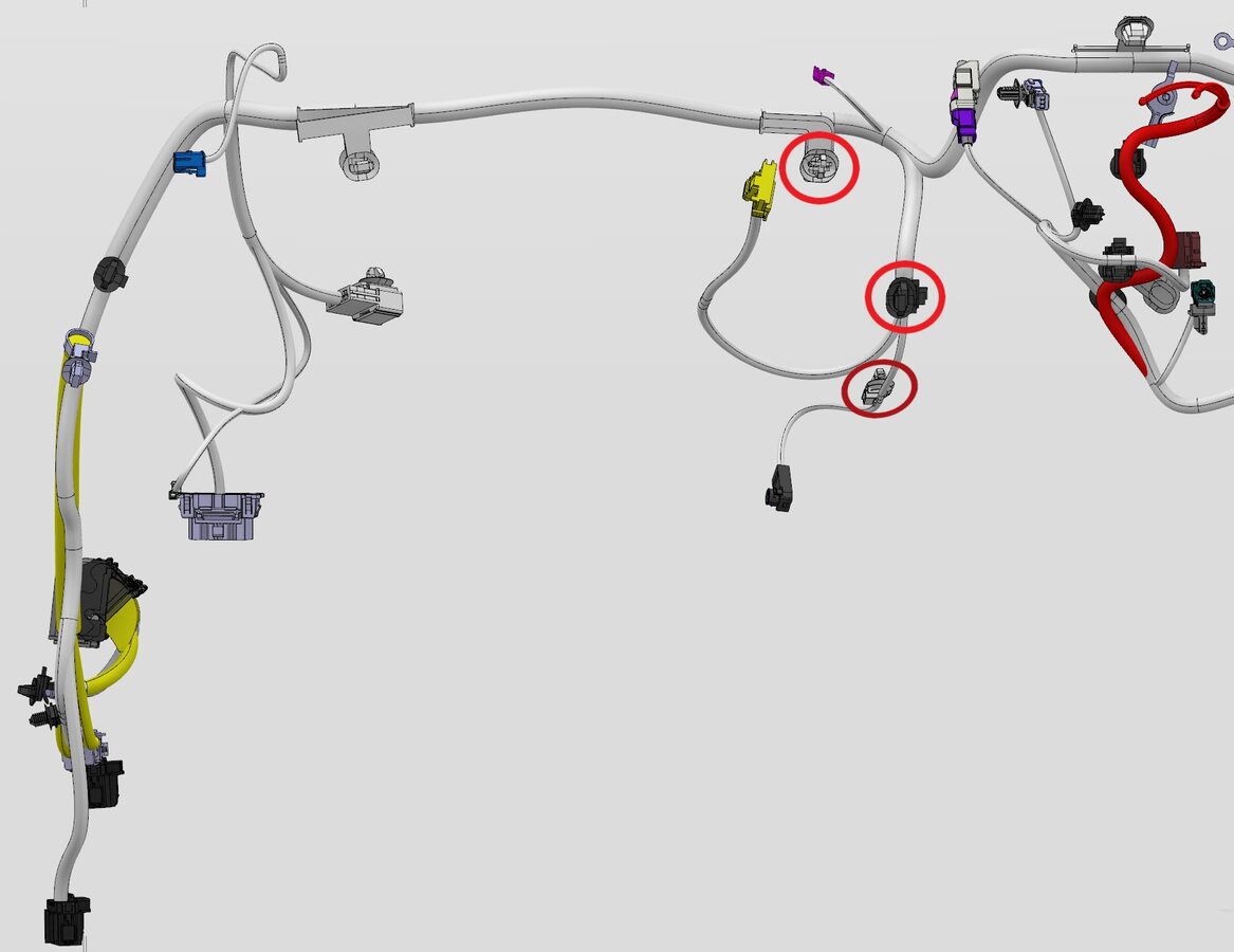
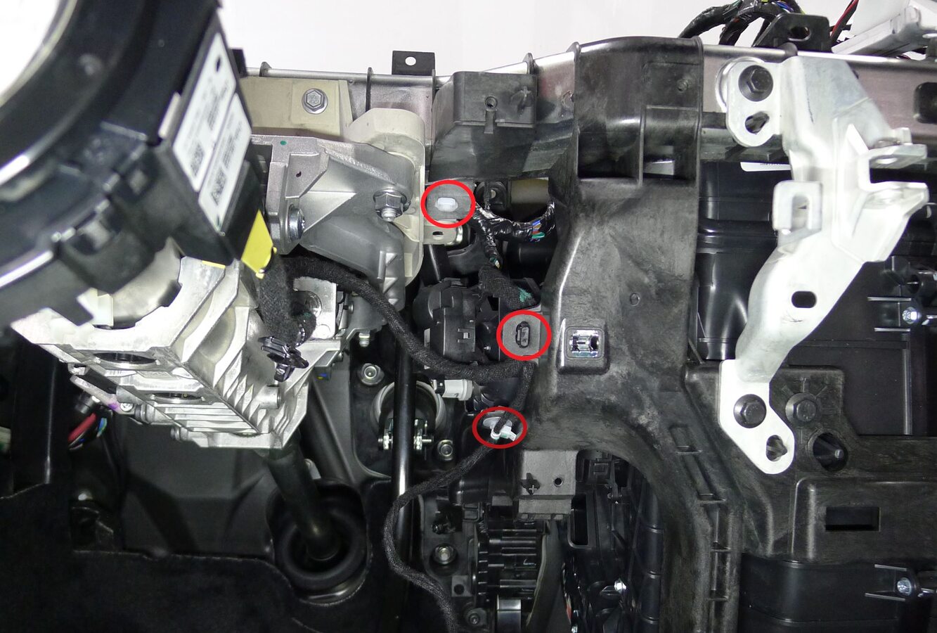
Secure IP harness to LH center IP carrier
注3x clips
-
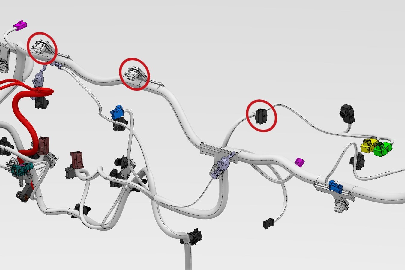
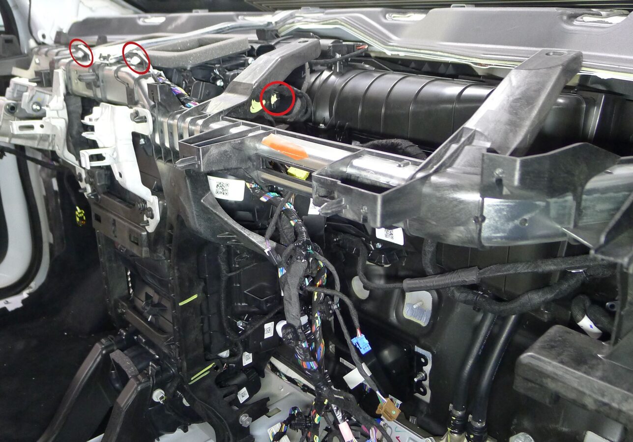
Secure IP harness at upper center IP carrier
注3x clips
-
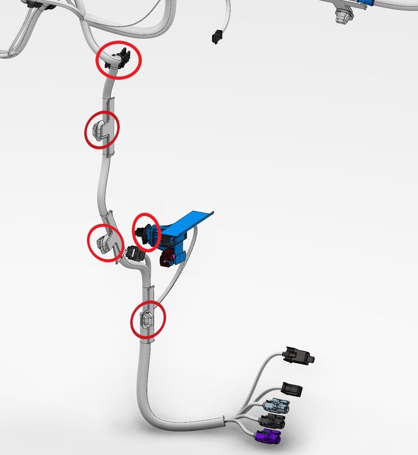
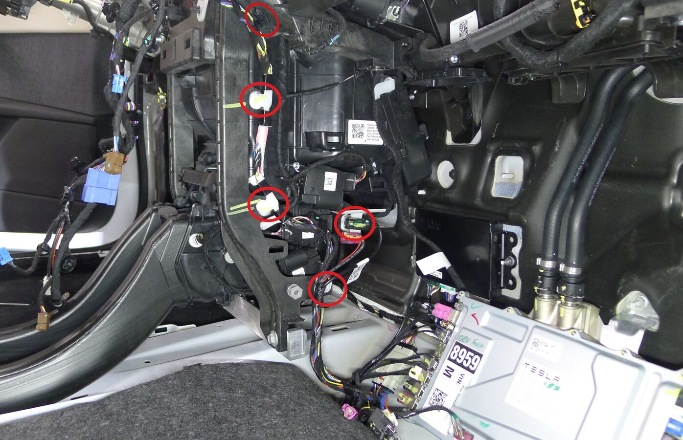
Secure IP harness to lower center IP carrier
注5x clips
-
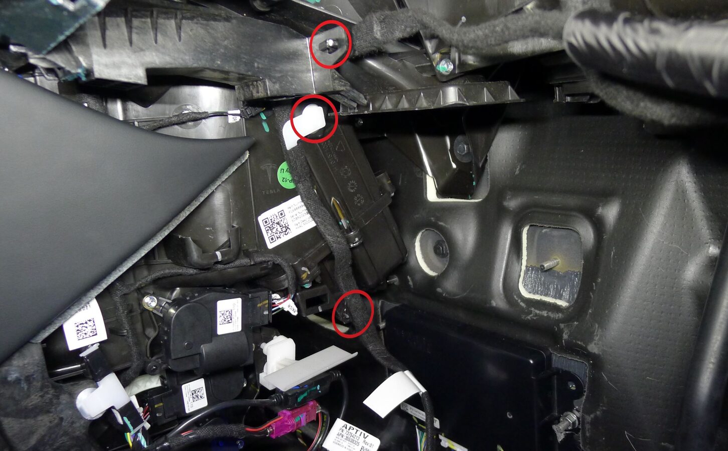
Secure glove box USB cable to IP carrier
注3x clips
-
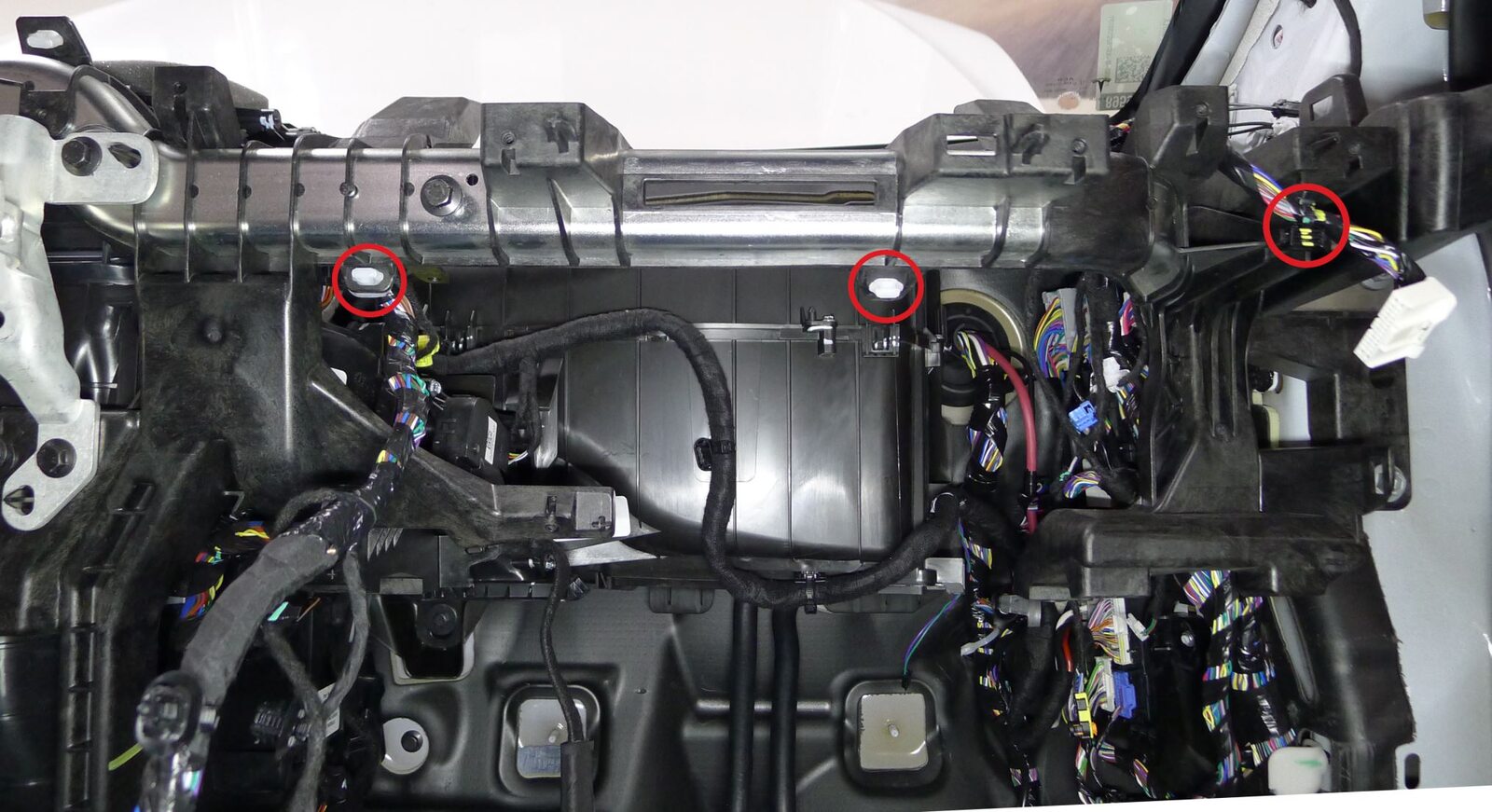
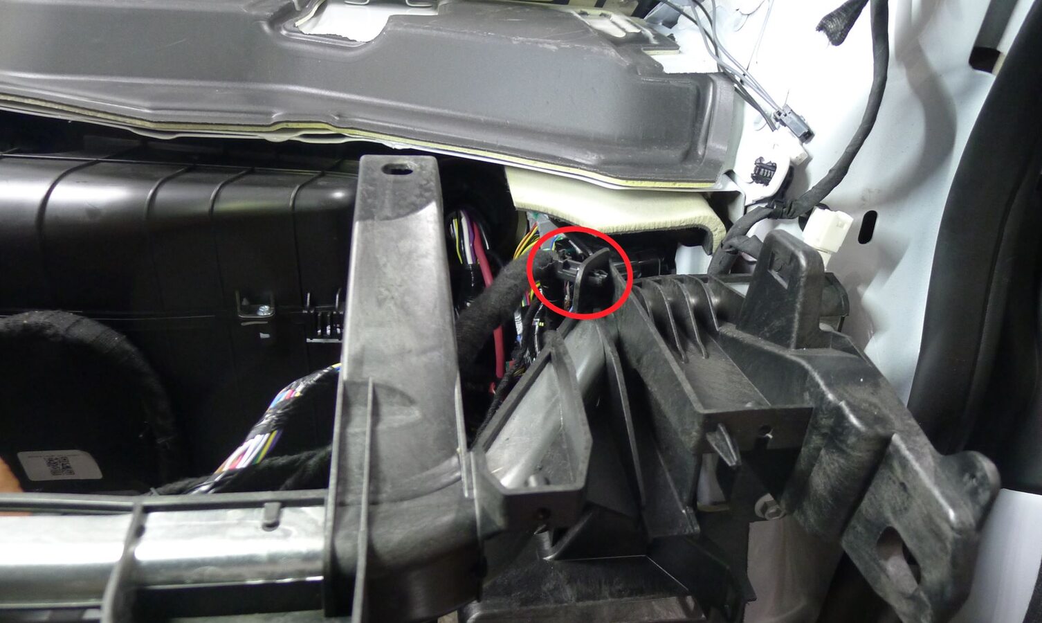
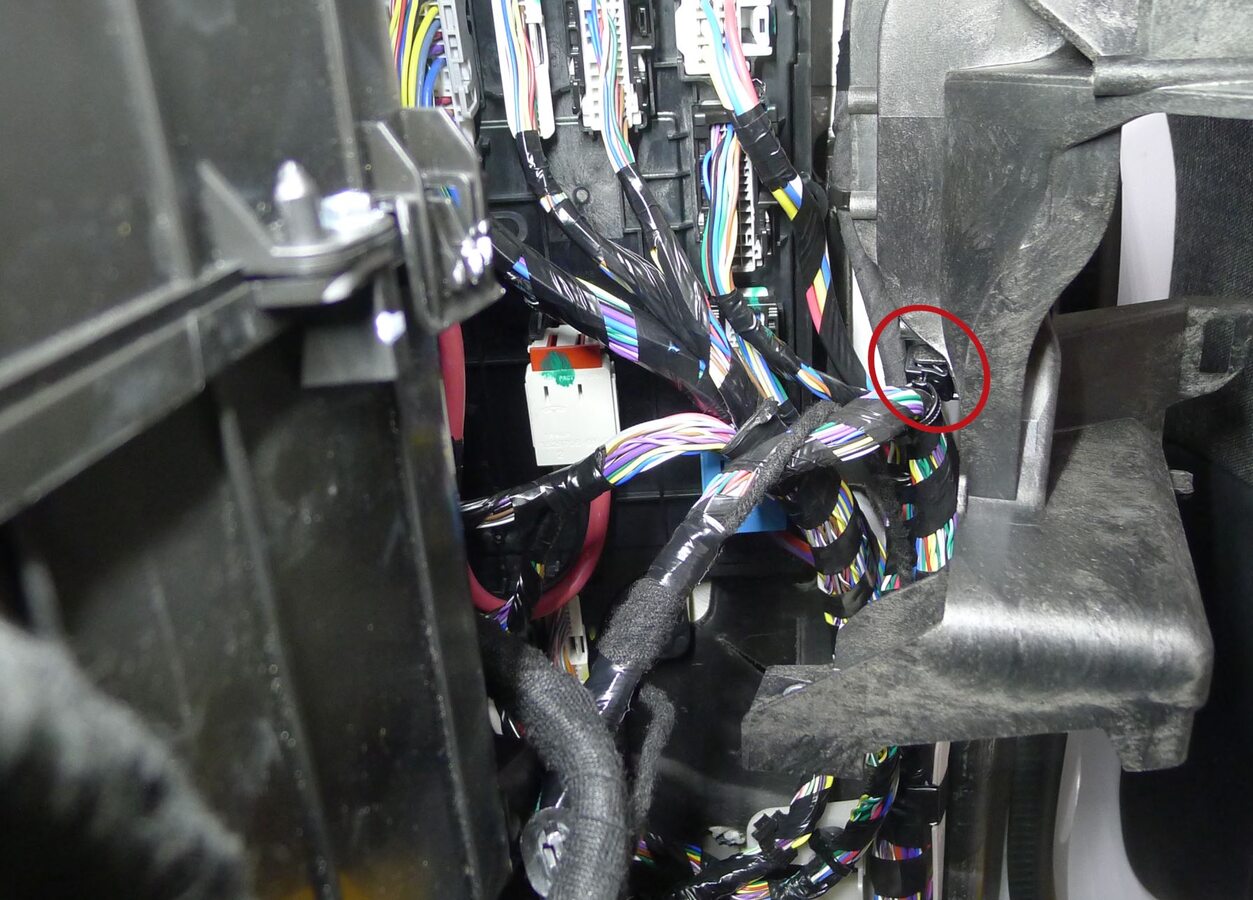
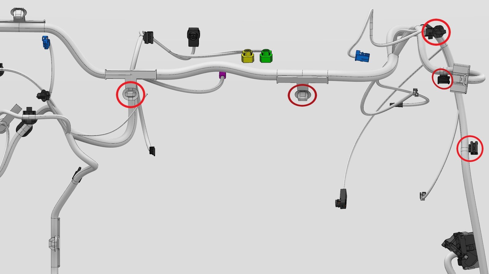
Secure IP harness to RH IP carrier
注5x clips
-
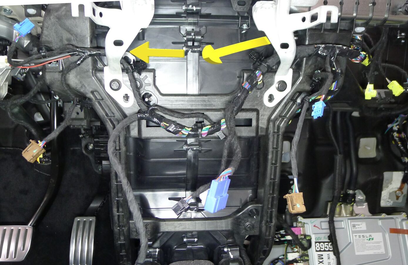
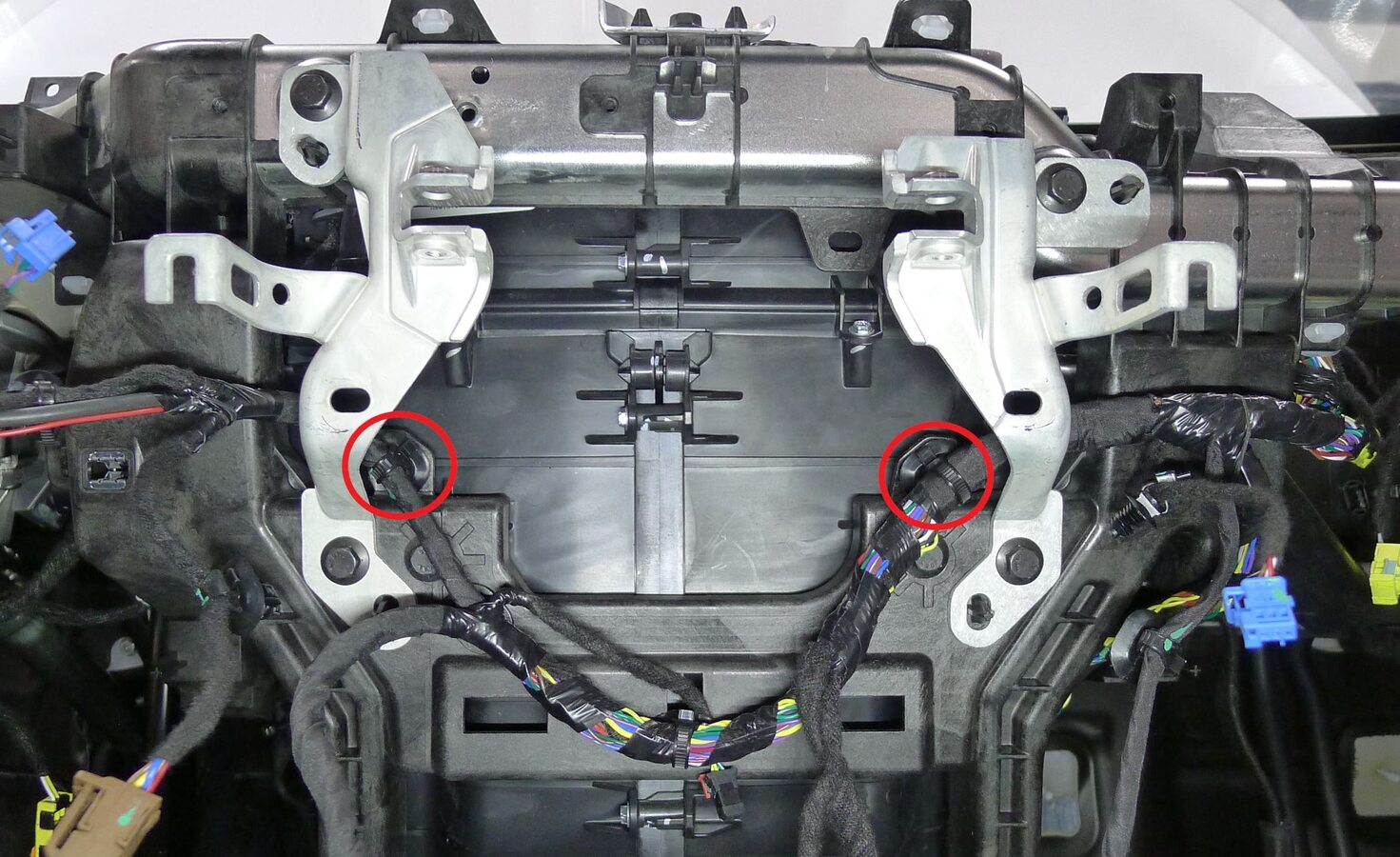
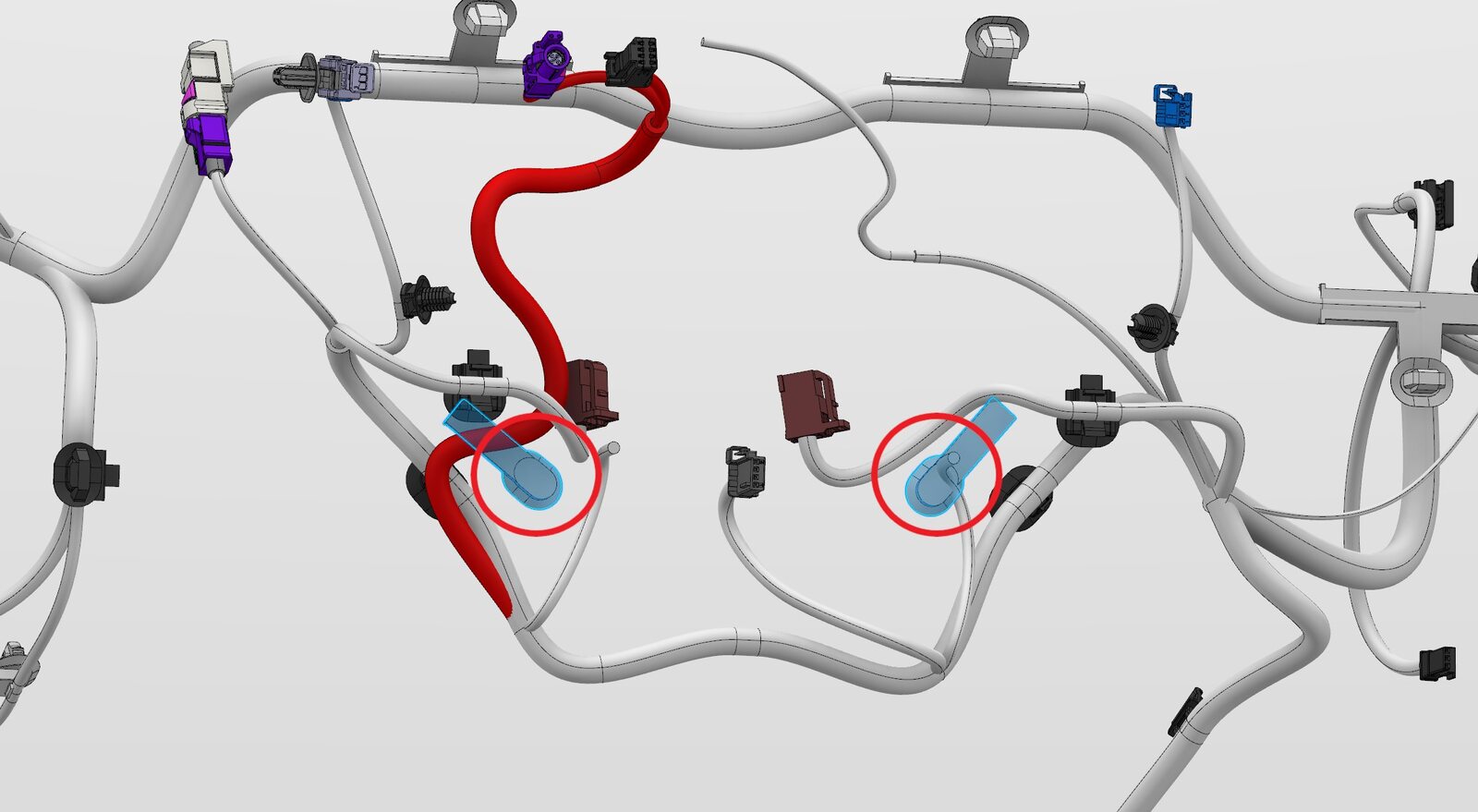
Secure IP harness to center IP carrier
注2x clips, Maneuver IP harness behind both center display brackets into position
-
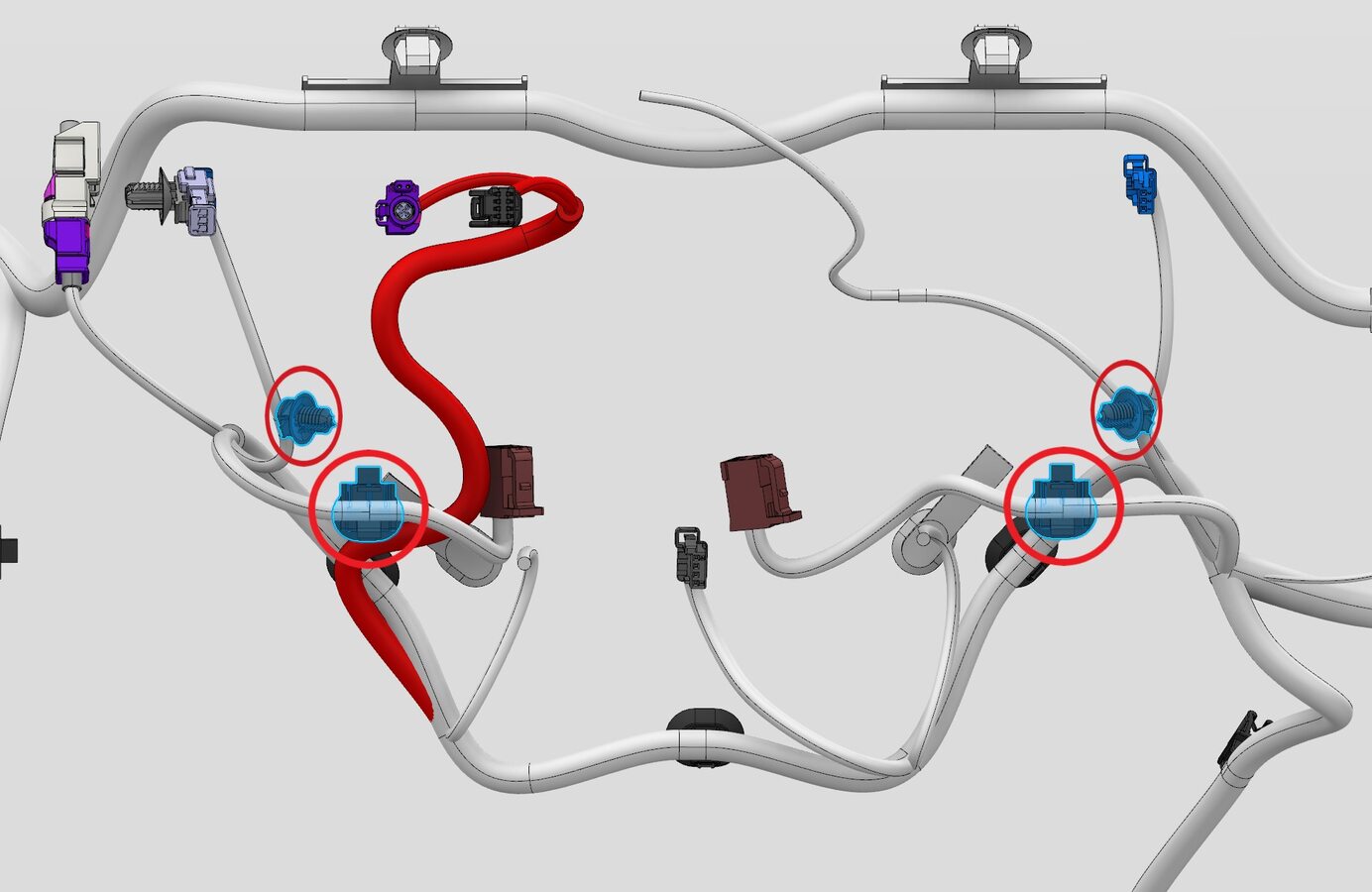
Secure IP harness at LH and RH center display brackets
注4x clips
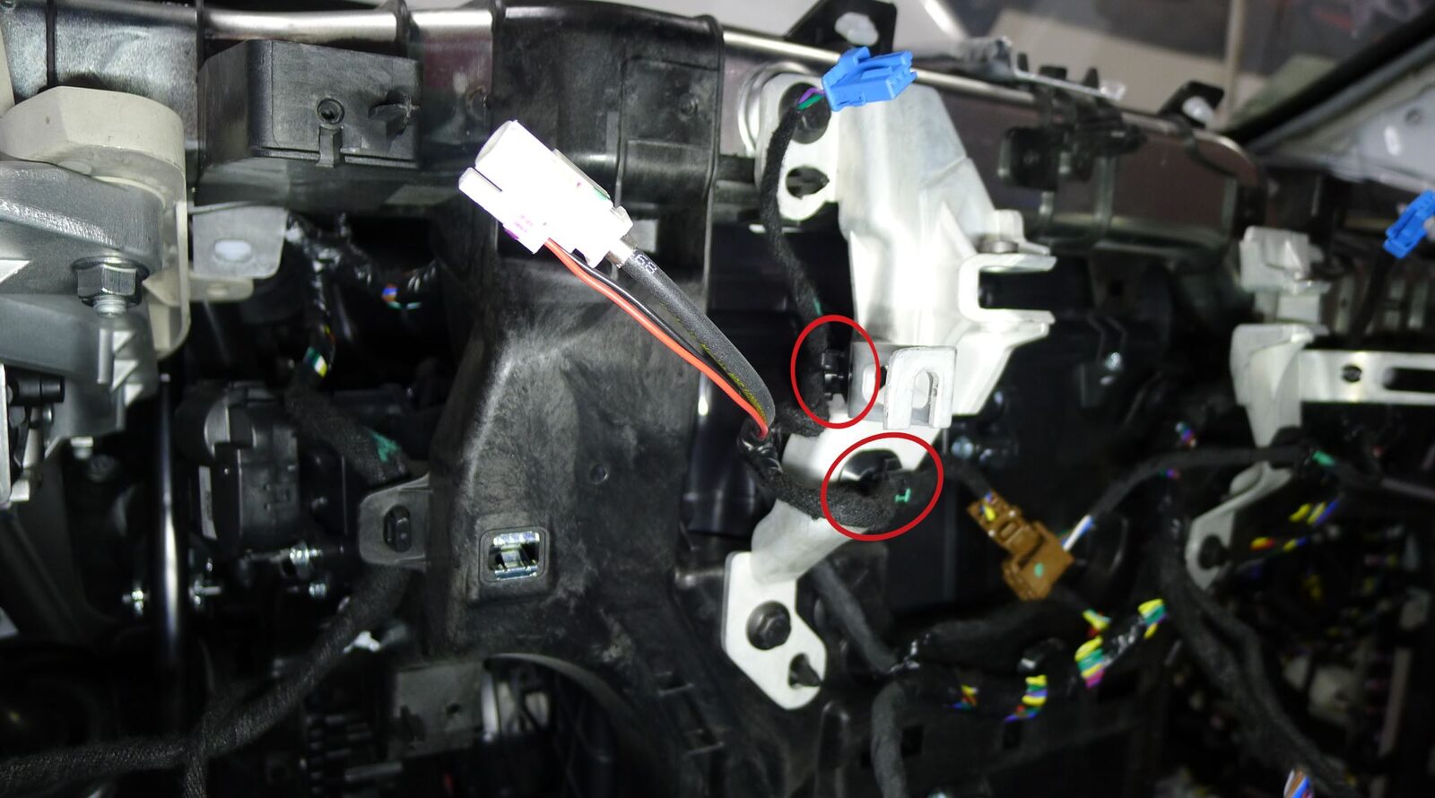
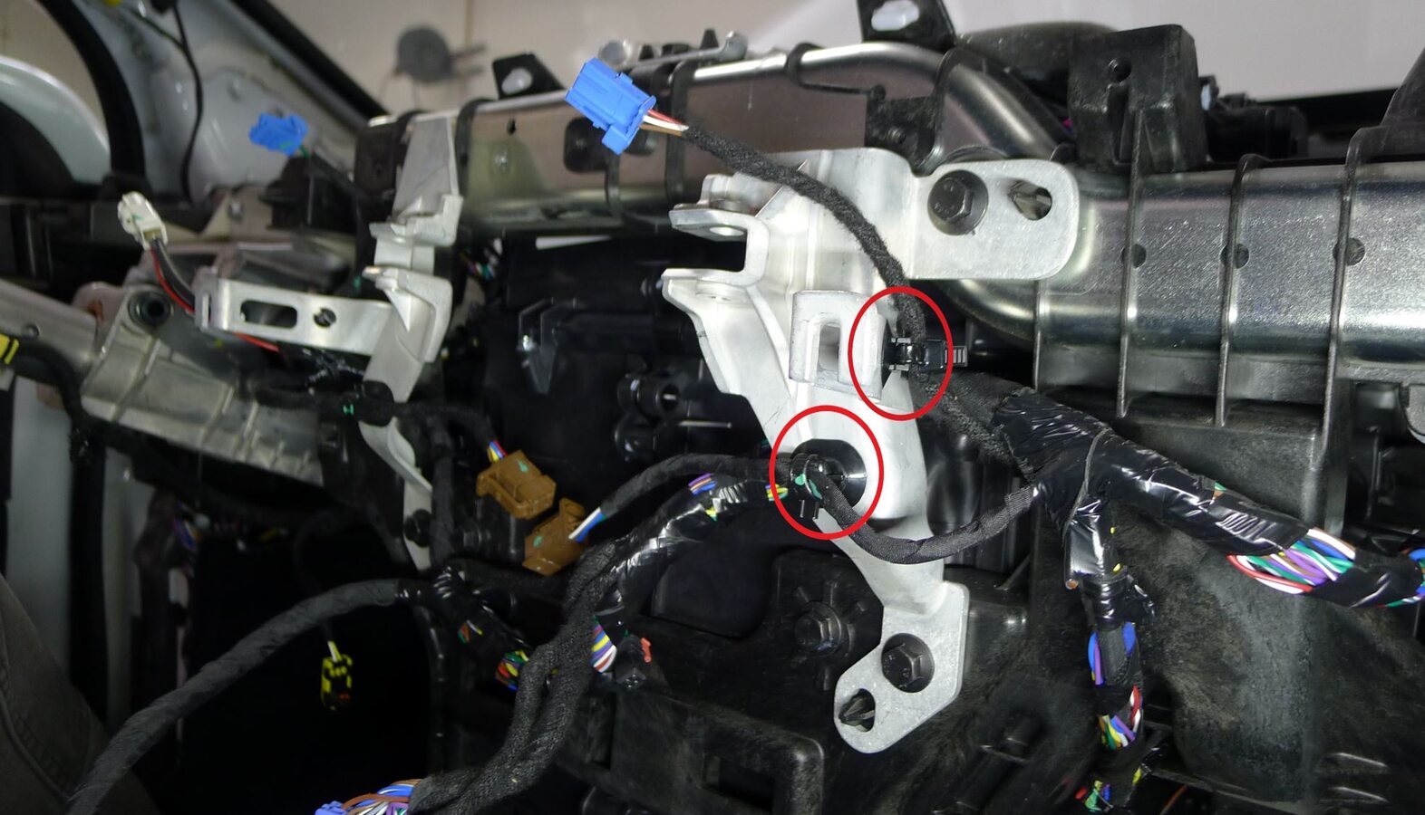
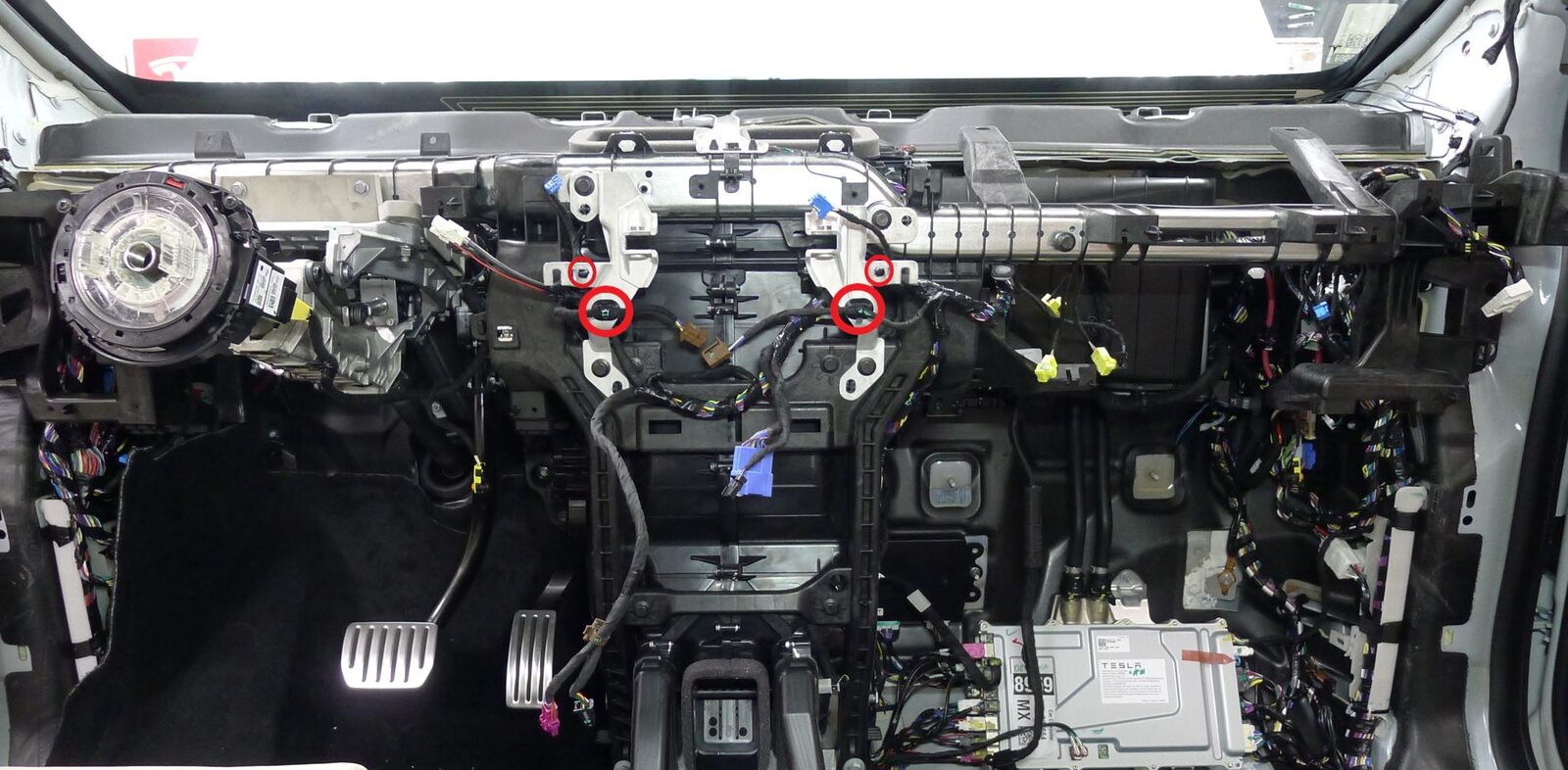
-
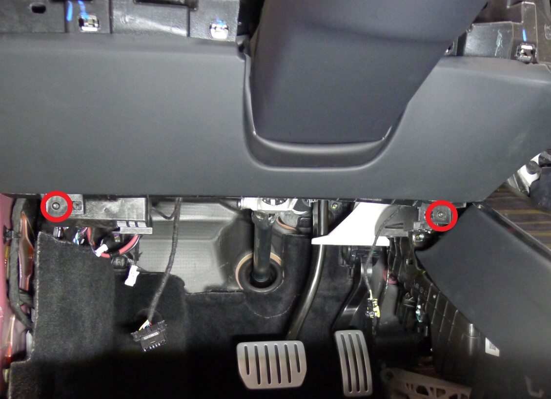
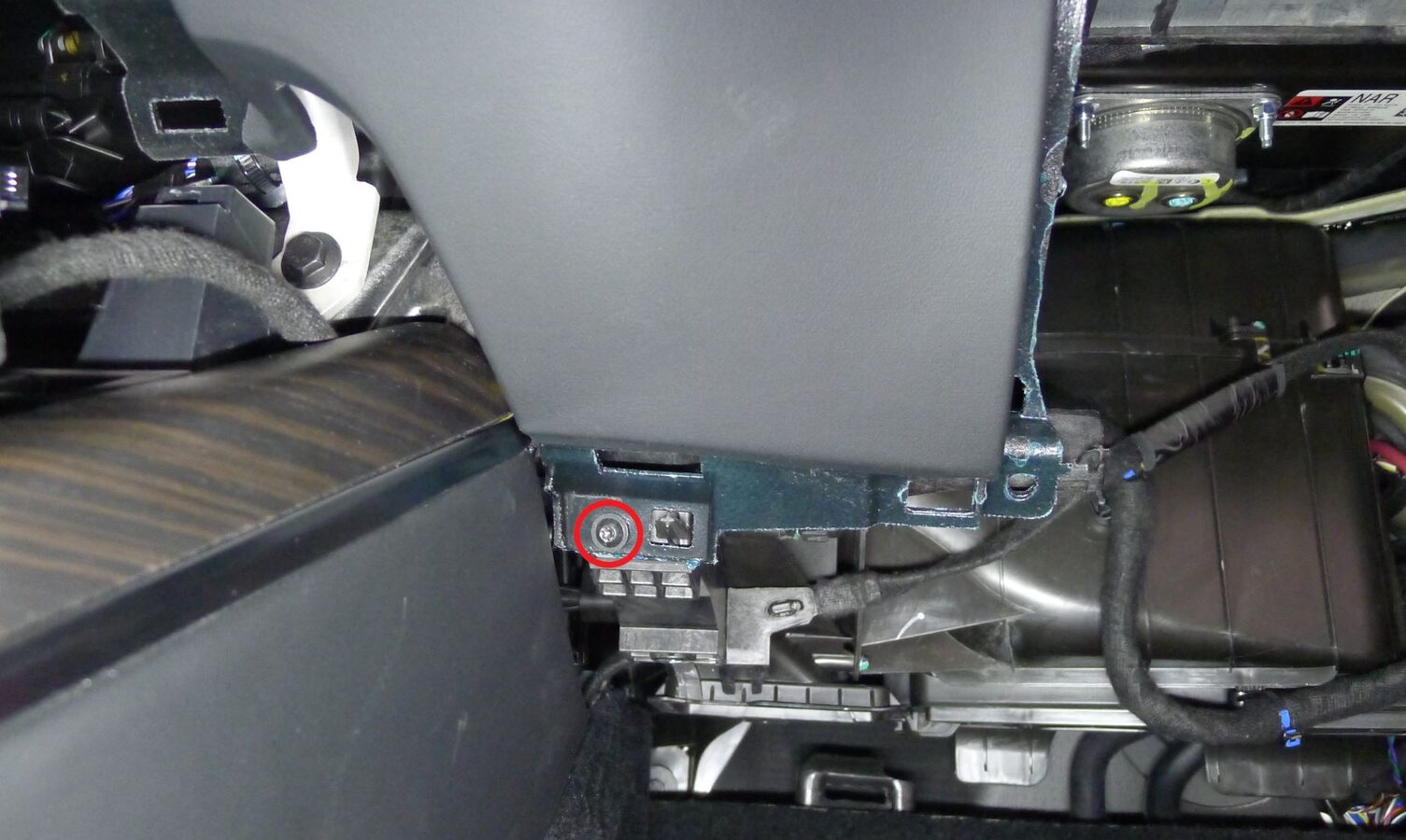
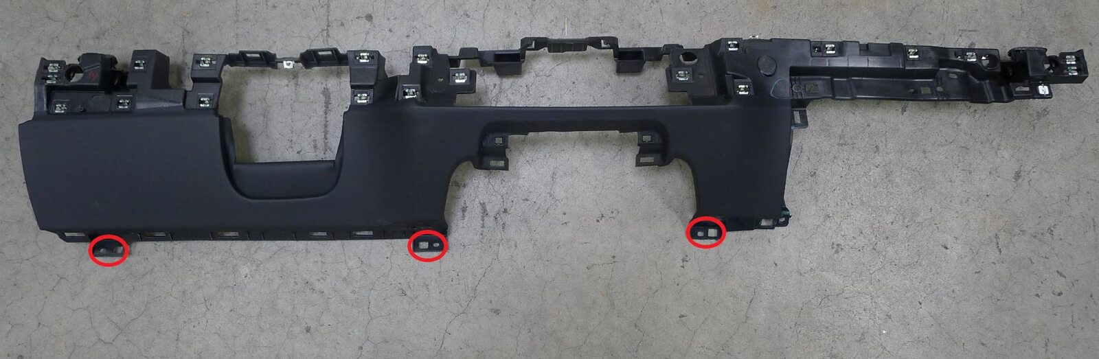
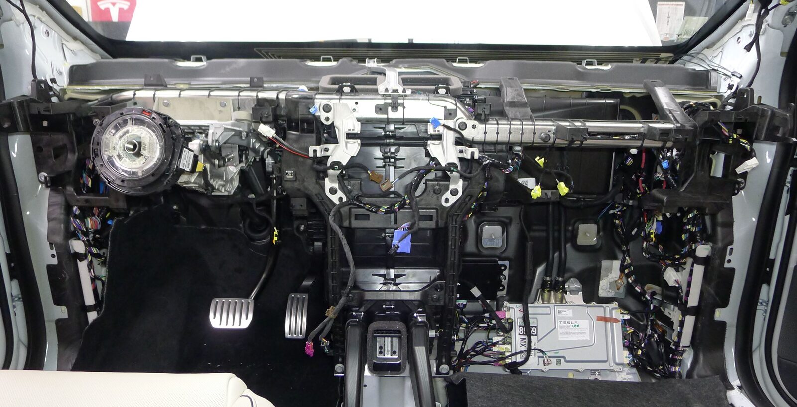
Secure lower instrument panel assembly
注3x screws, T20, 3 Nm, 8x tabs, Secure only the screws located at bottom of assembly, Remainder of screws are secured at a later step

-
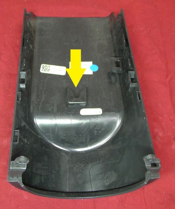
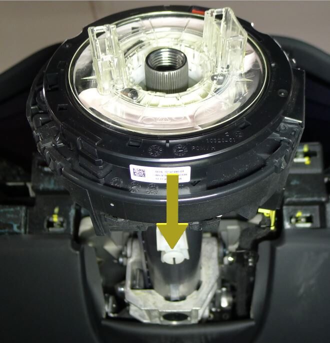
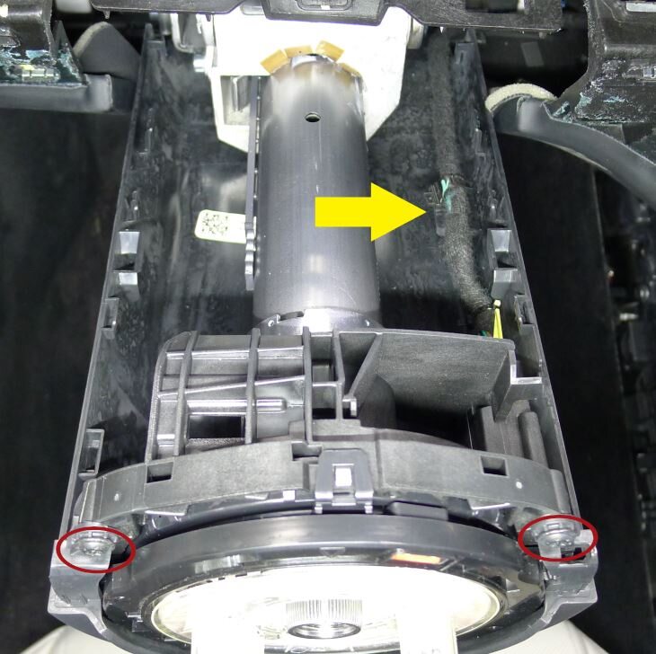
Install lower shroud to steering column
注2x screws, T20, 1.5 Nm, 1x clip, 1x datum, Slide lower shroud forward to engage datum
-
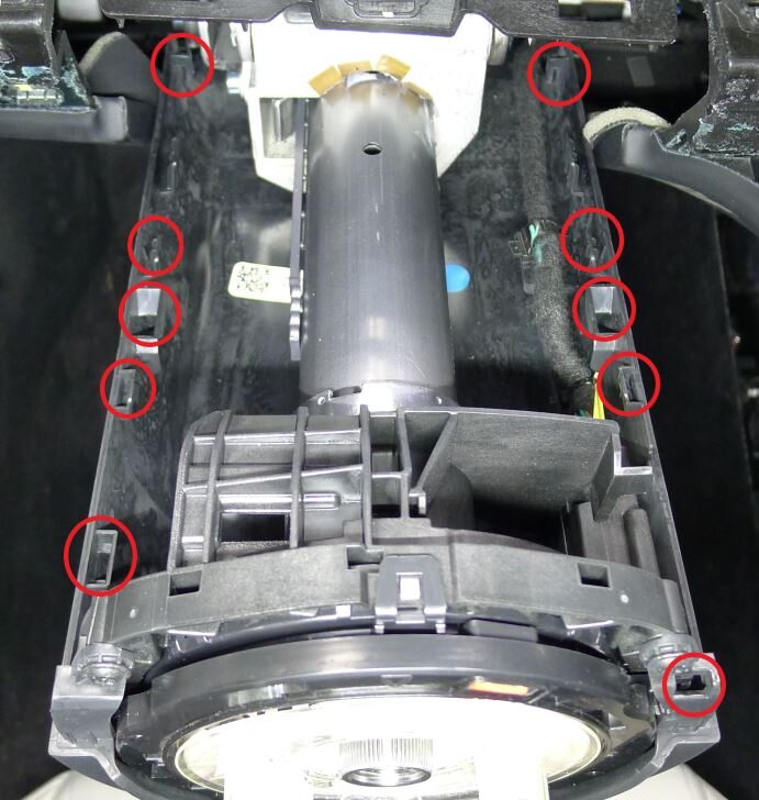
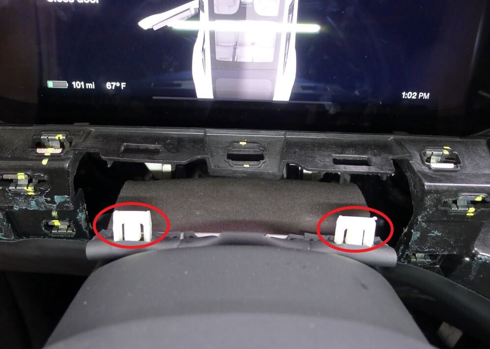
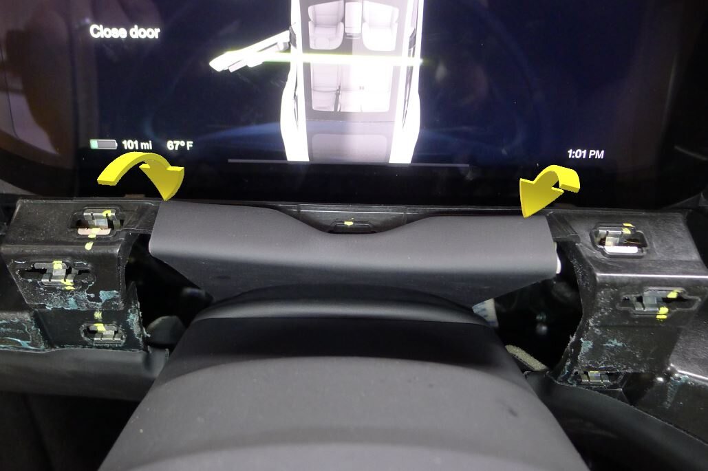
Align the clips and datums then press downward to install upper shroud onto lower shroud
注6x clips, 4x datums

-
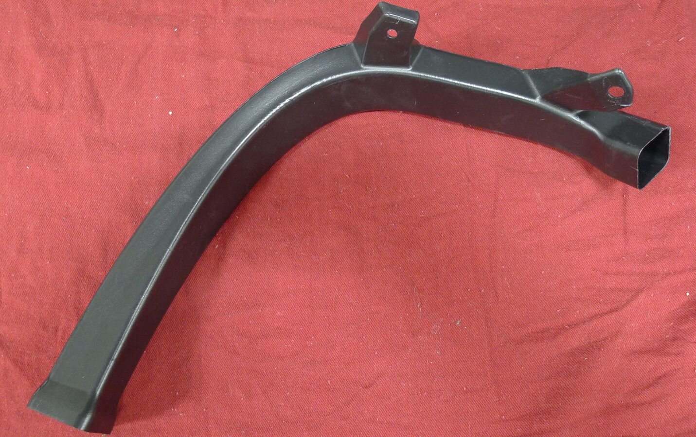
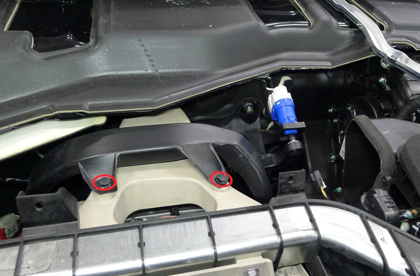
Install driver floor jumper left foot duct
注2x push clips
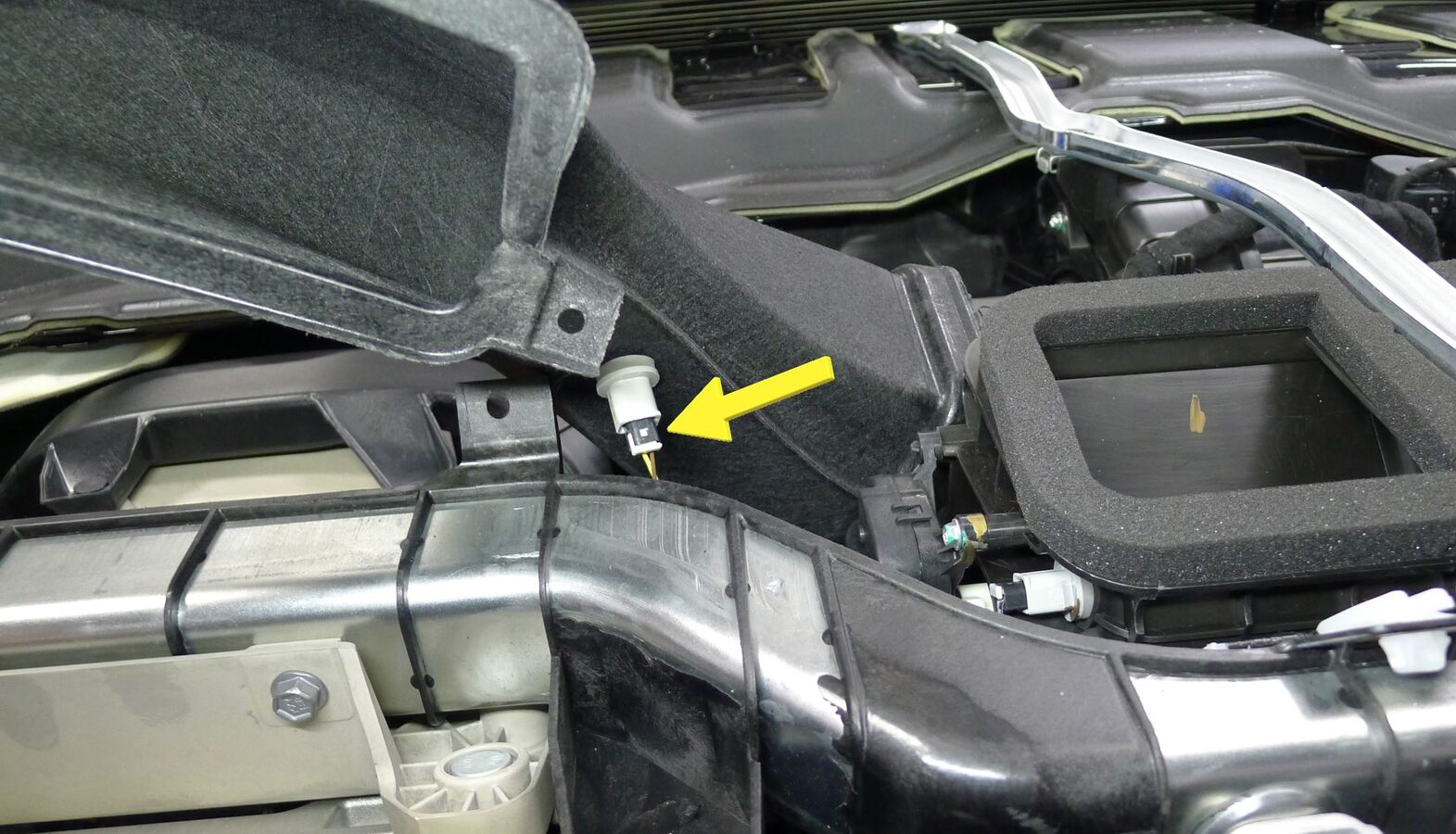
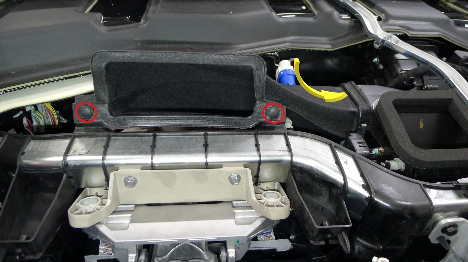
-
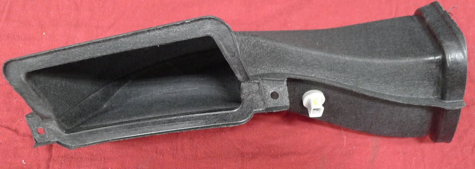
Install driver IP air vent duct
注2x rivets, 1x connector, Slide inboard and into HVAC unit assembly
-
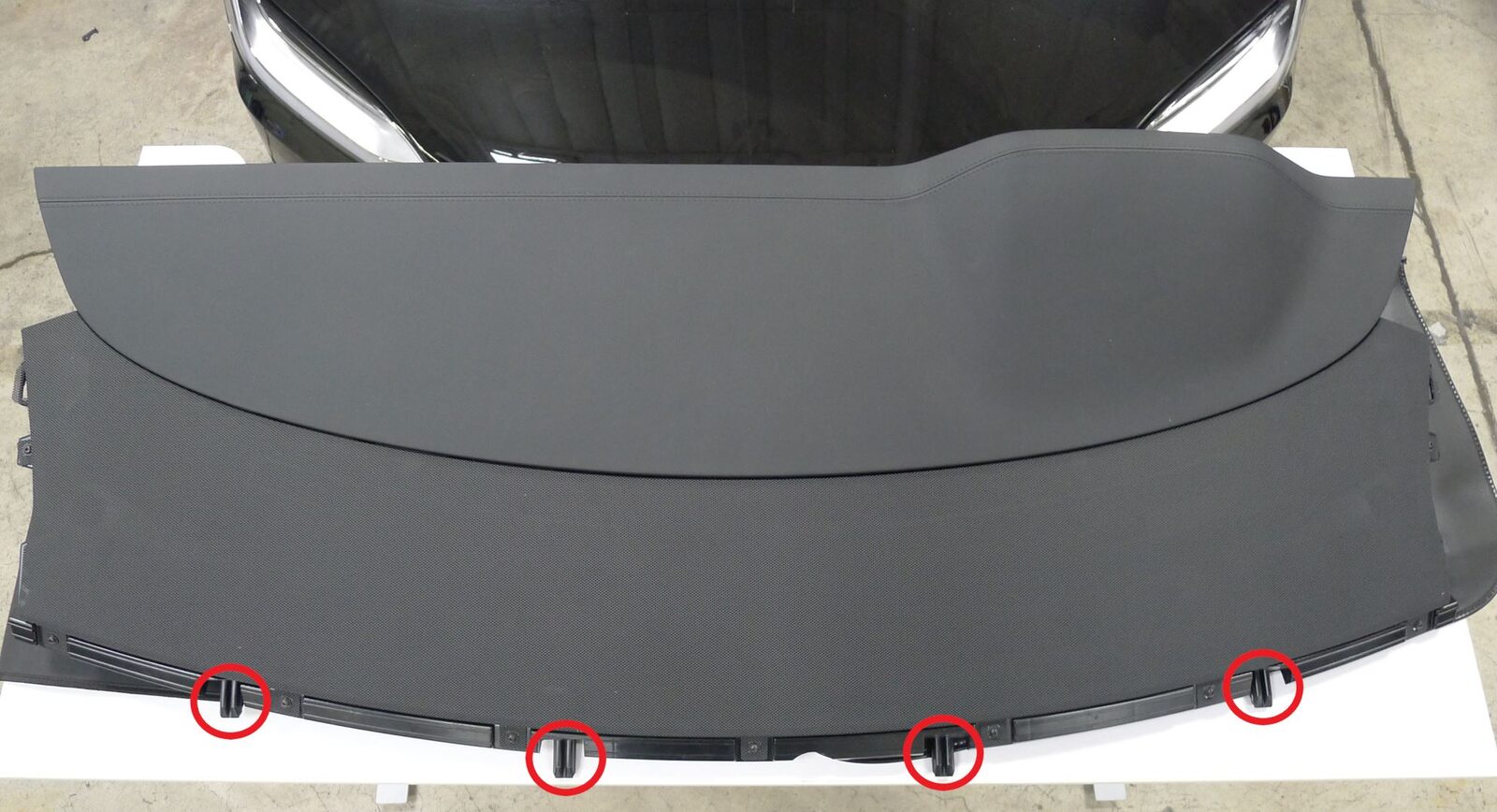
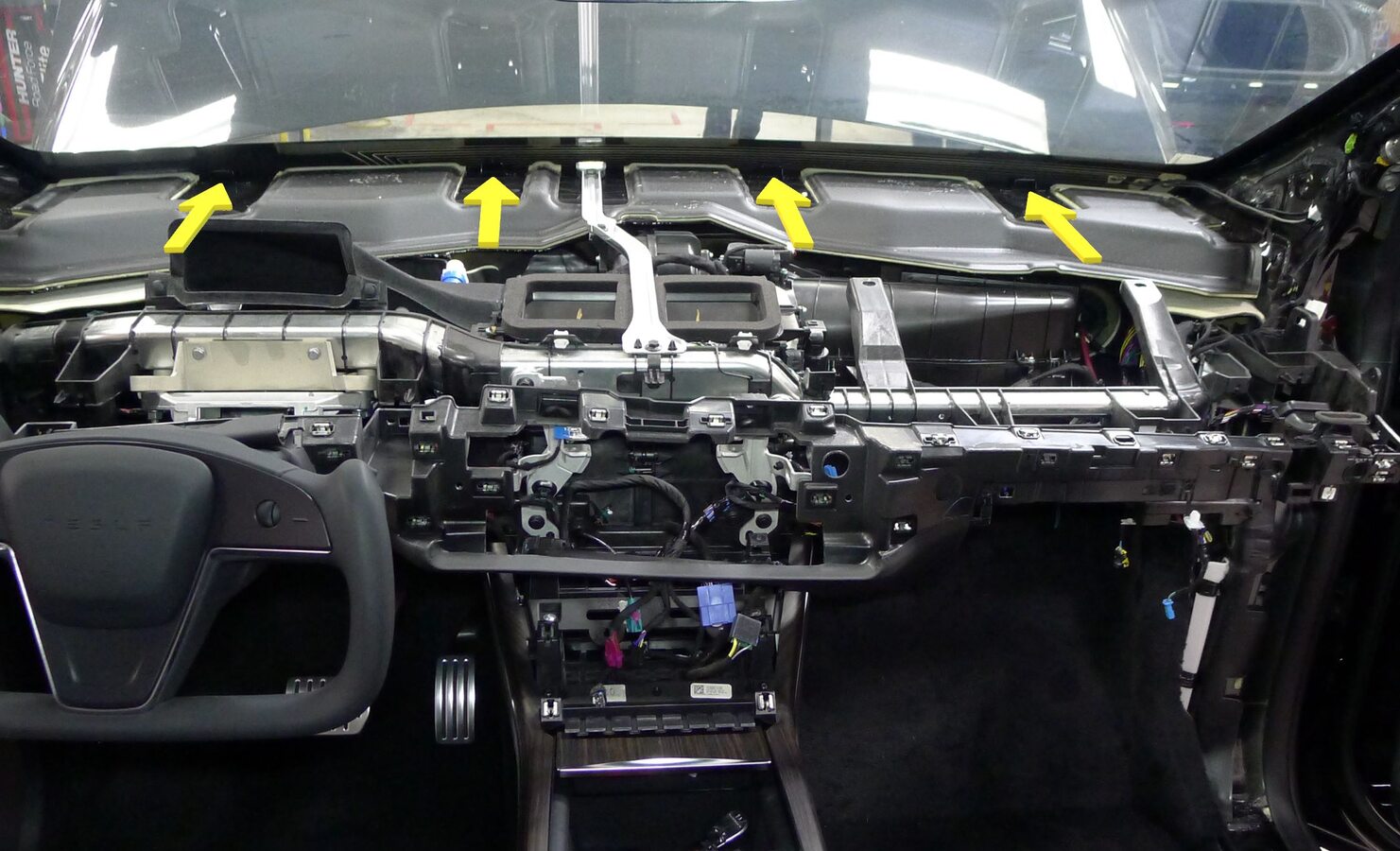
Install IP sub-assembly
注4x datums, Slide IP sub-assembly into vehicle, Ensure passenger air bag and driver vent assembly have clearance past lower IP assembly, Engage IP sub-assembly datums into dash slots, Recommend assistance

-
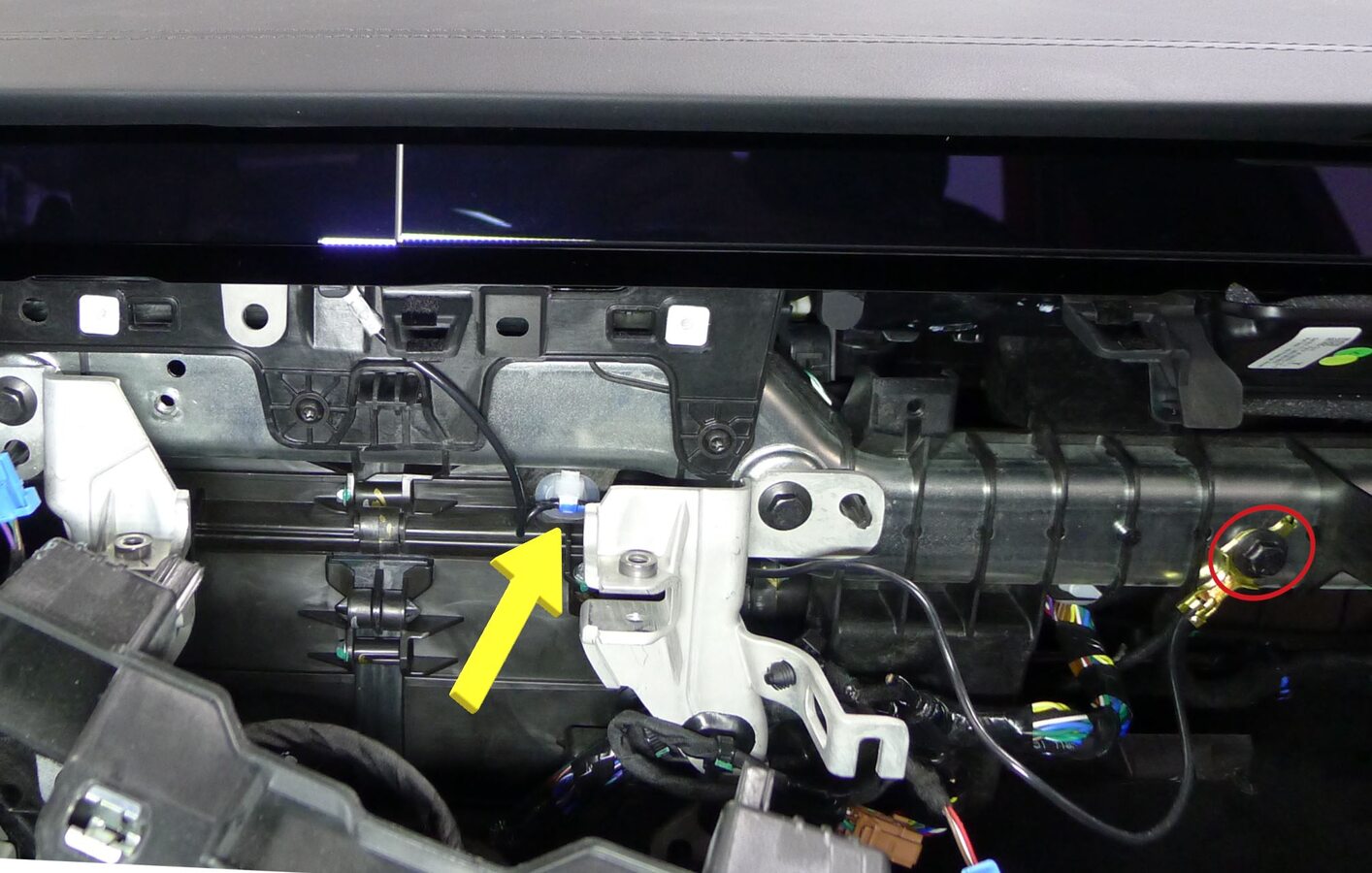
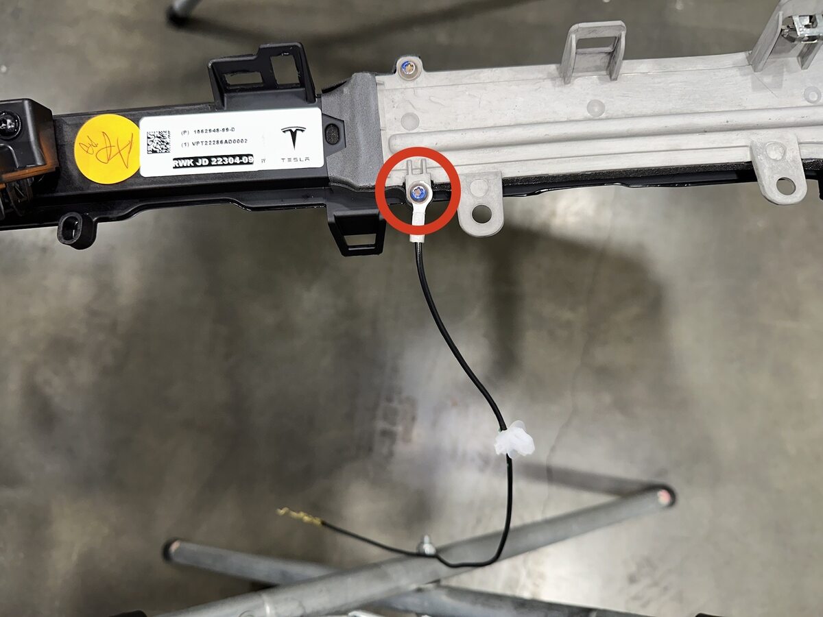
Secure IP ground harness
注1x clip, 1x bolt, 10mm, 3.5 Nm, Note routing behind center display RH bracket. If using part revision 1562948-70-D on a Non-AP4 vehicle, add ground strap 1679240-00-A to aero lens assembly
-
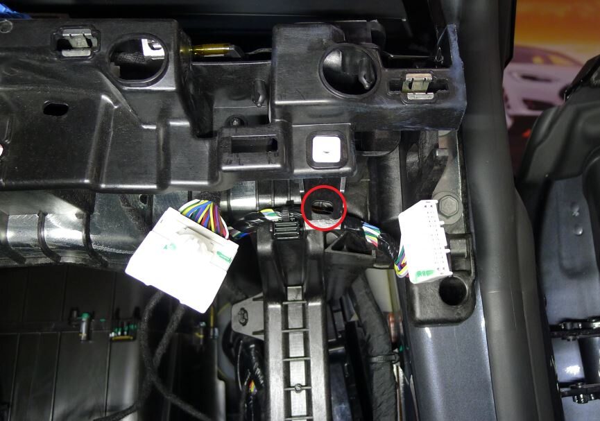
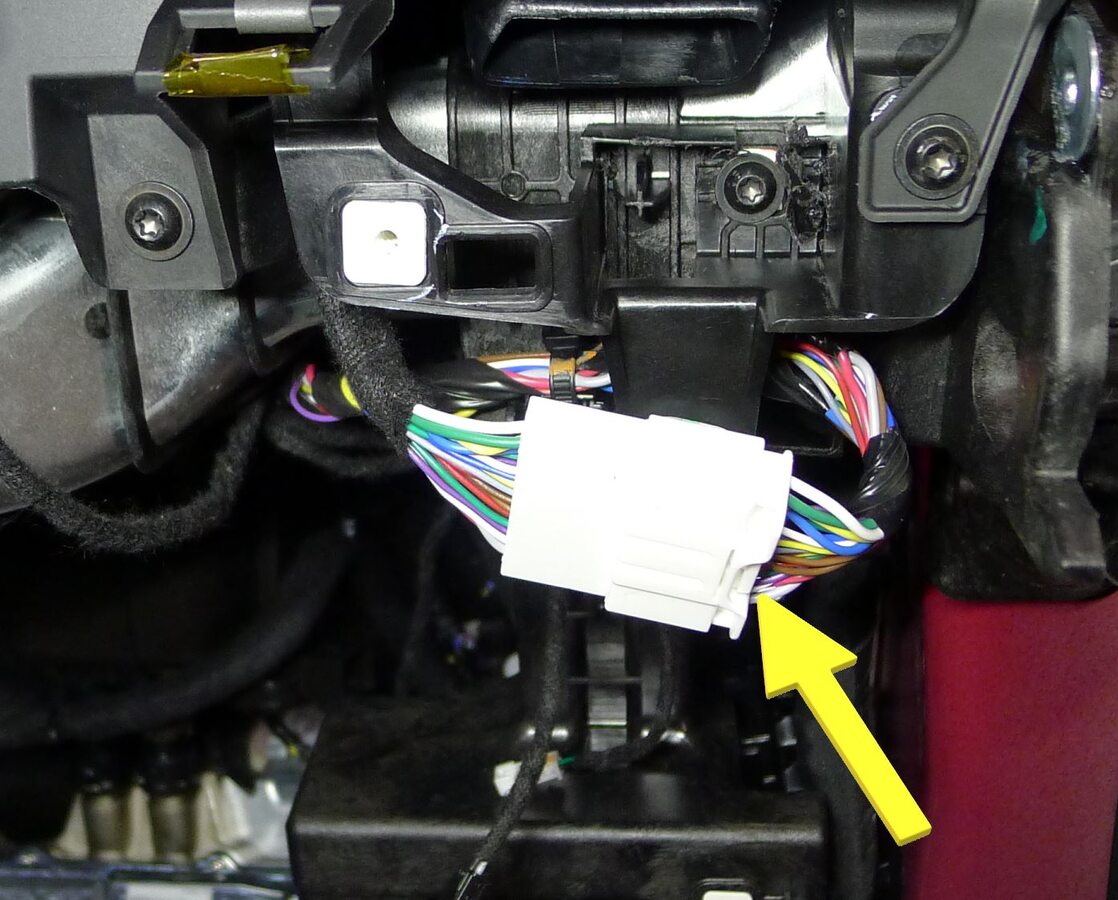
Secure IP trim harness
注1x connector, 1x clip
-
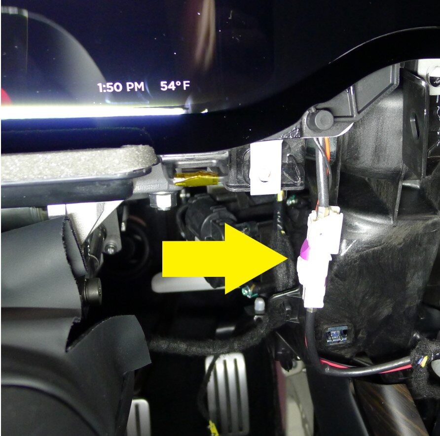
Secure instrument cluster harness
注1x connector
-
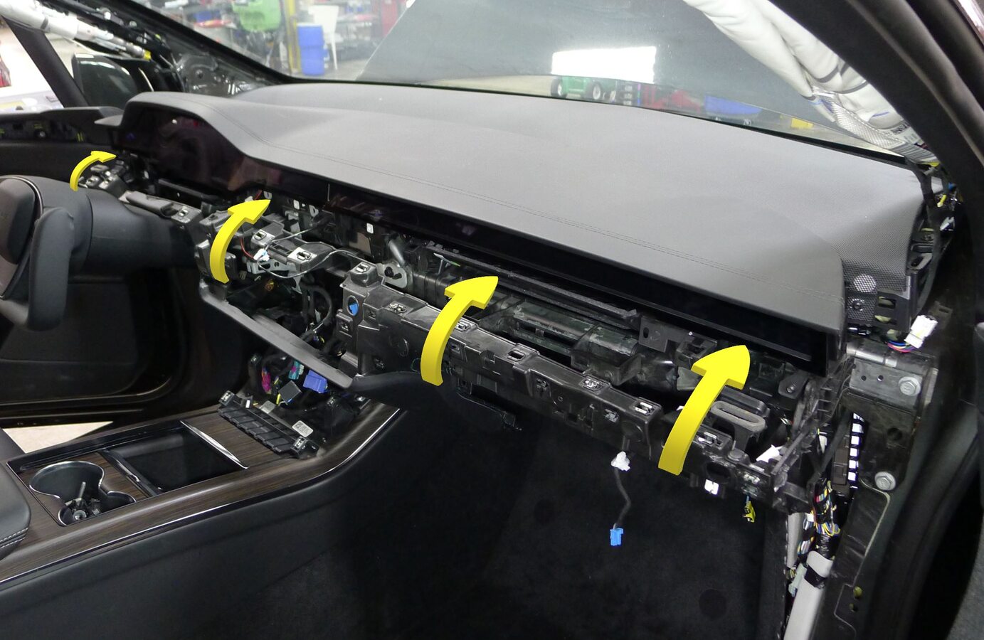
Position lower instrument panel assembly into IP sub-assembly
-
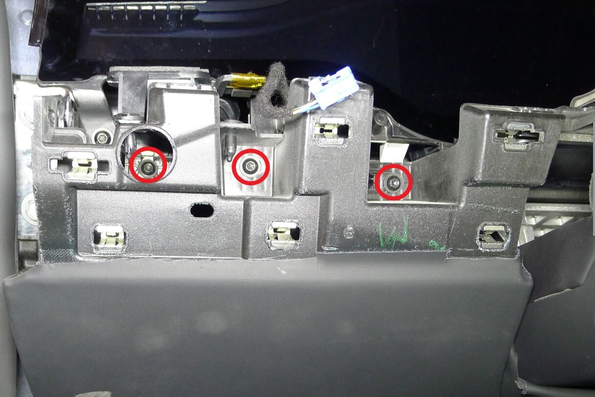
Secure LH lower instrument panel
注3x screws, T20, 3 Nm
-
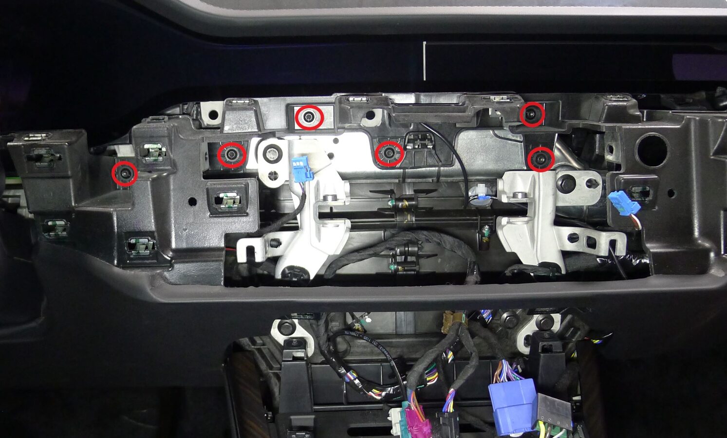
Secure center lower instrument panel
注6x screws, T20, 3 Nm
-
Secure RH lower instrument panel
注3x screws, T20, 3 Nm
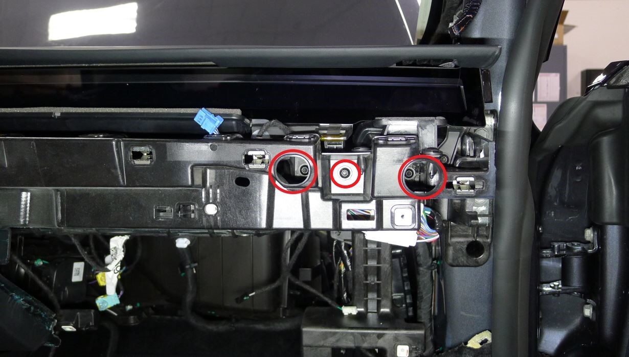
-
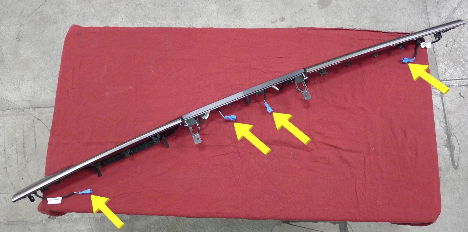
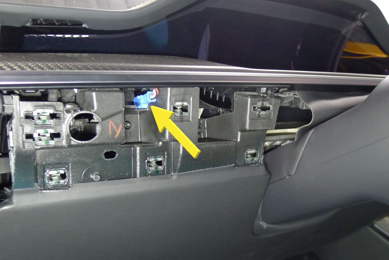
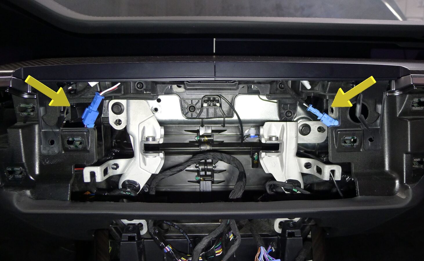
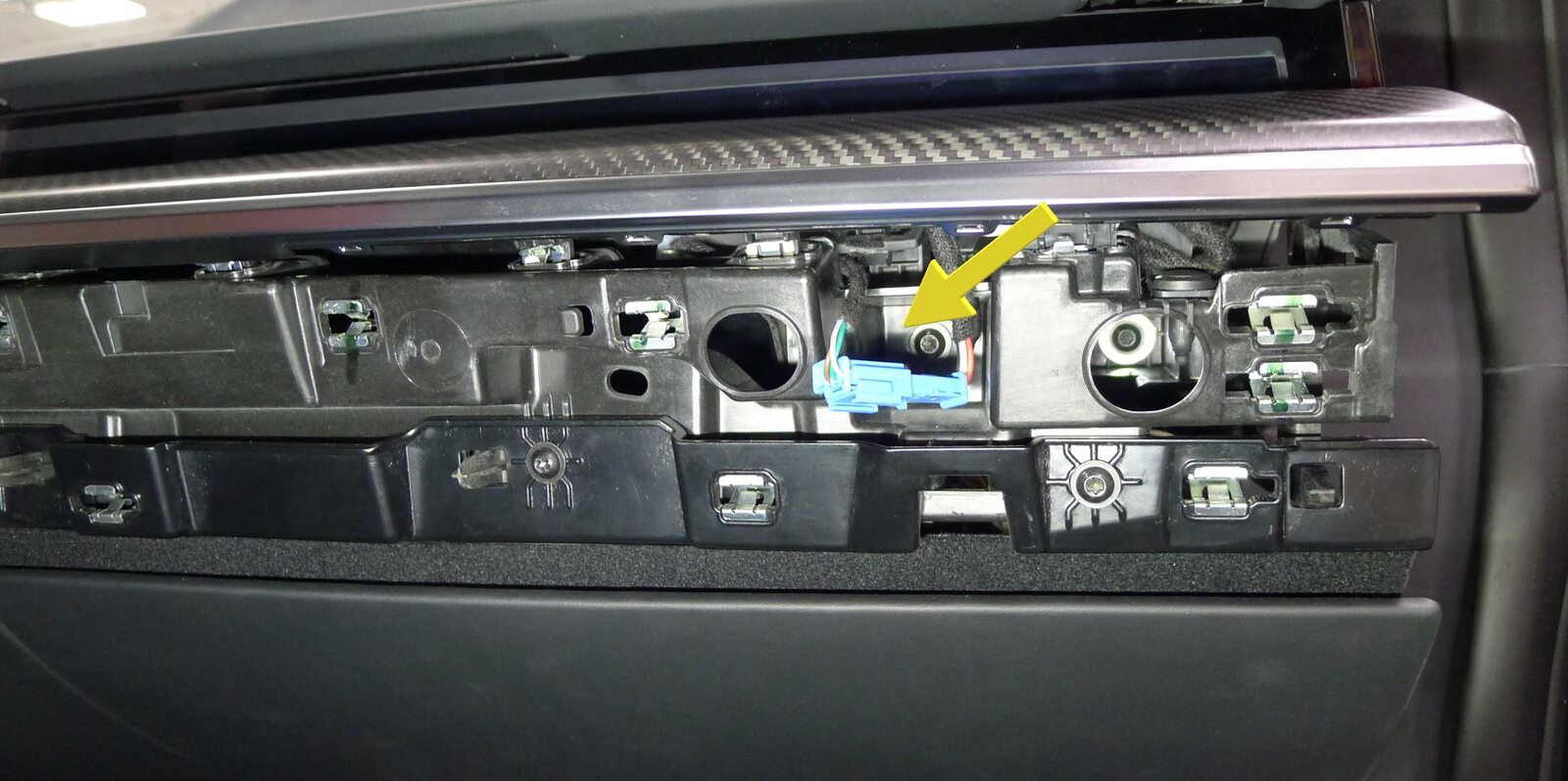
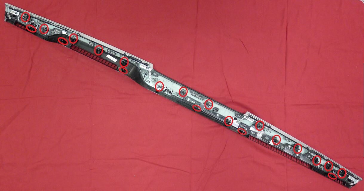
Install IP Decor
注21x clips, 6x datums, 4x connectors, Connect ambient bright harness, Secure each IP decor connector clip to IP carrier, Secure IP decor to lower instrument panel
-
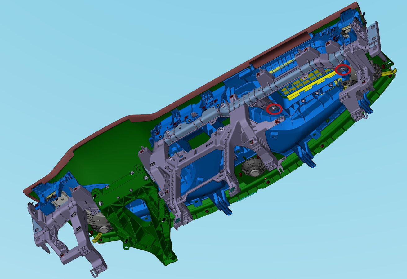
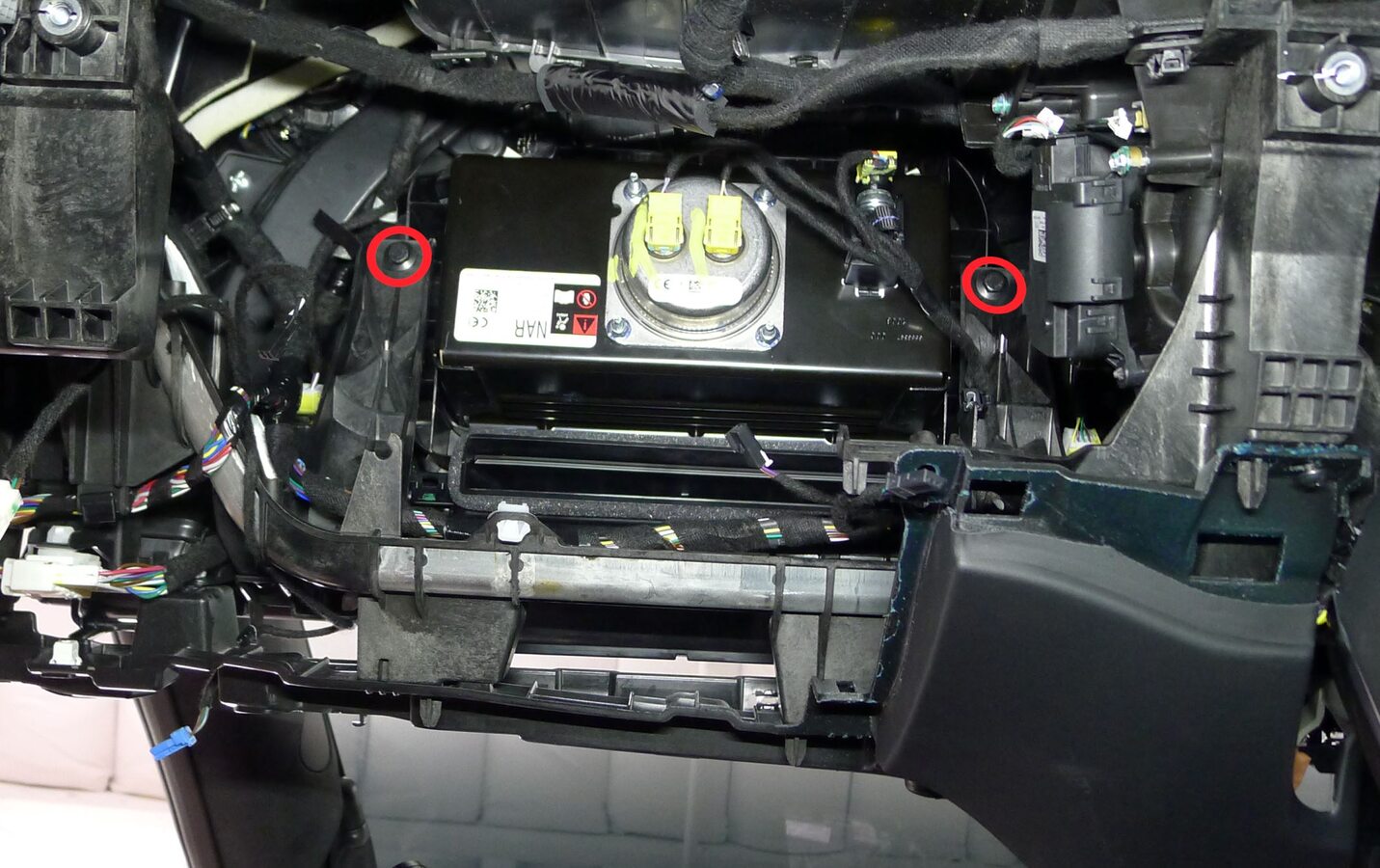
Install IP carrier cross beam bolts
注2x bolts, 10mm, 3 Nm
-
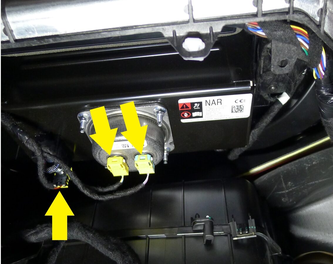
Secure passenger IP airbag connectors
注3x connectors
-
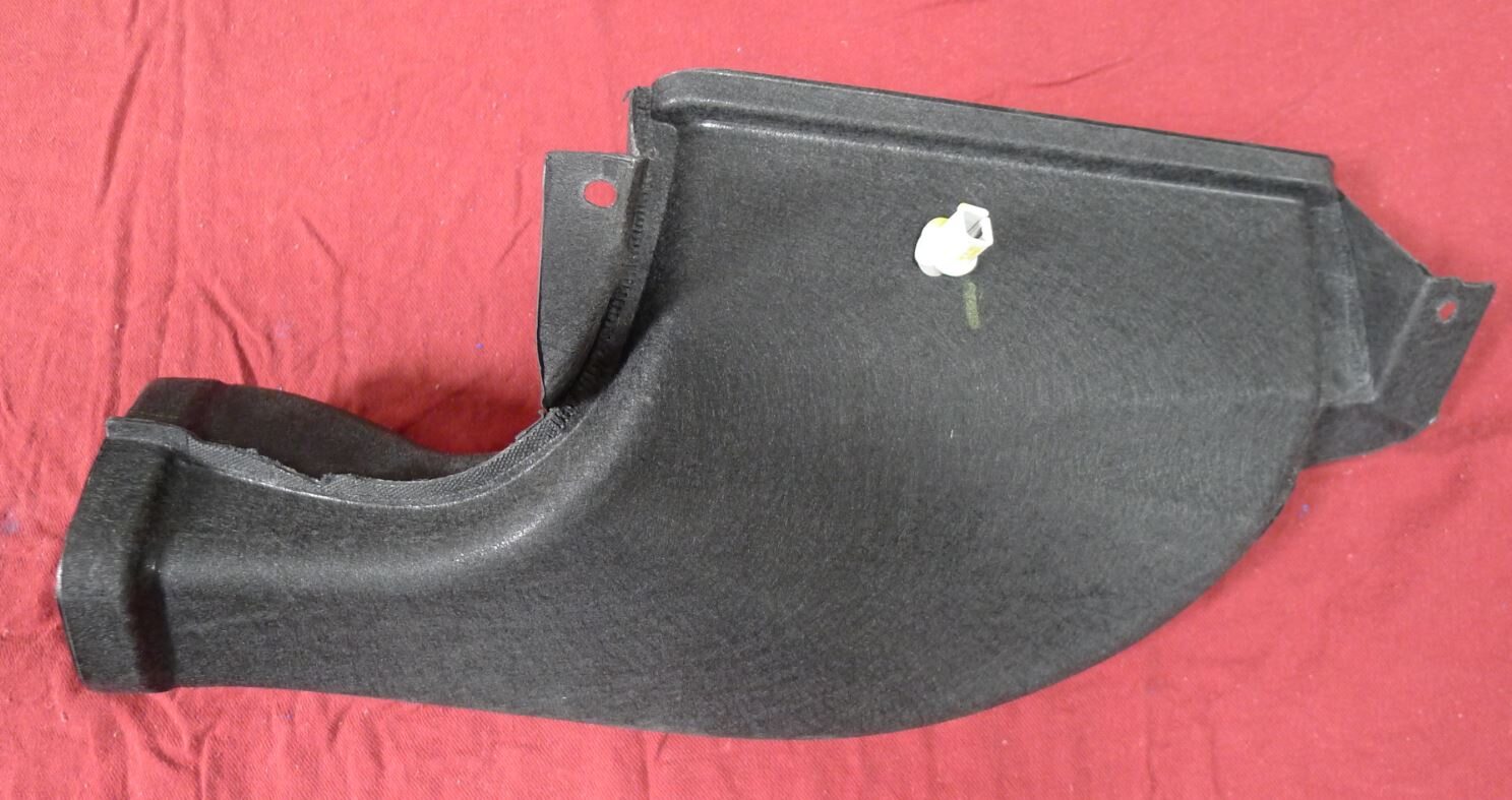
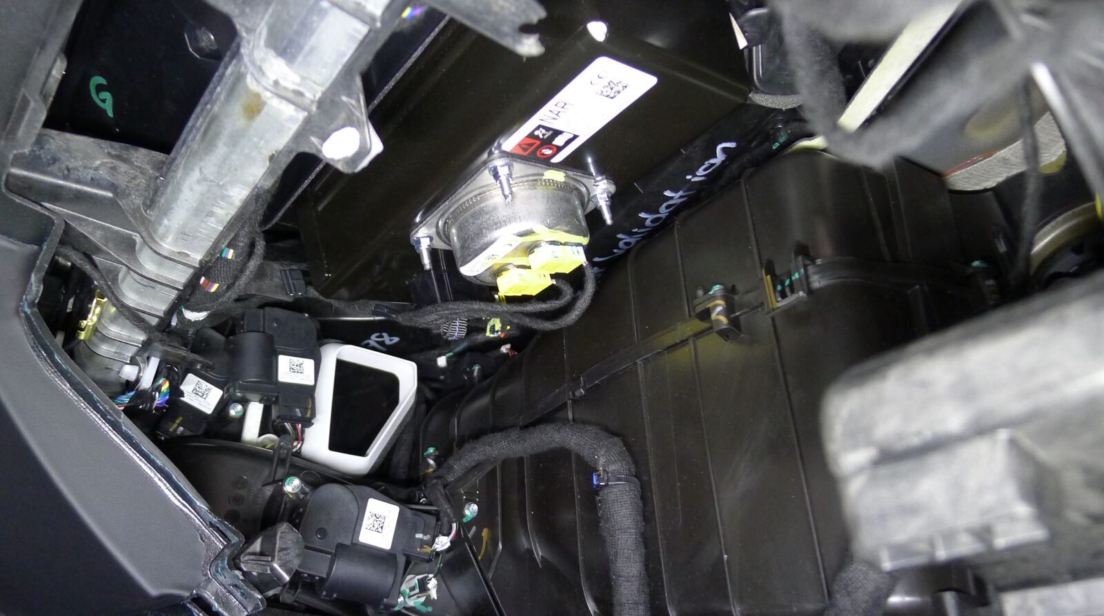
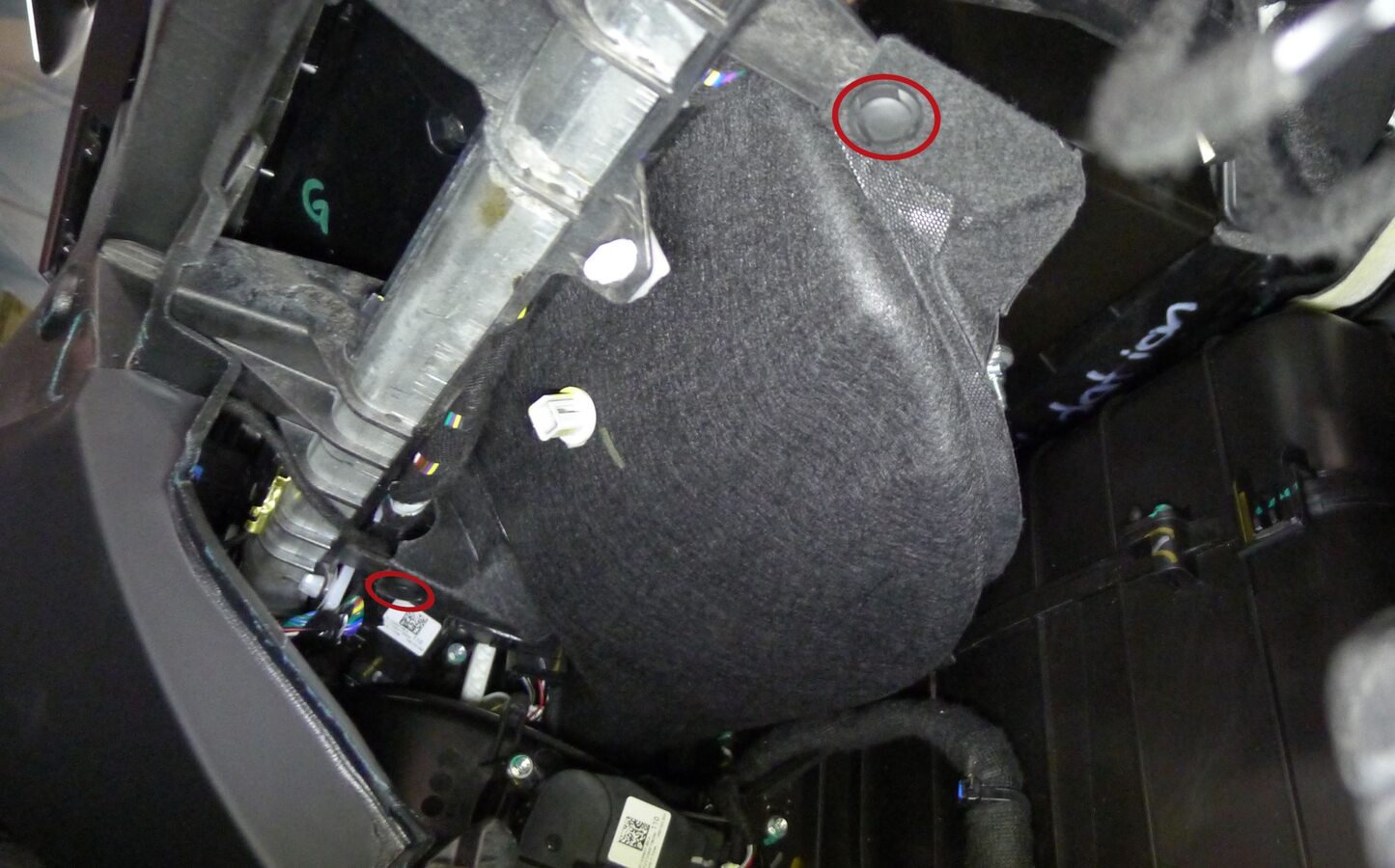
Install passenger IP air duct
注2x push-pull rivets
-
Secure passenger IP air duct temperature sensor connector
注1x connector
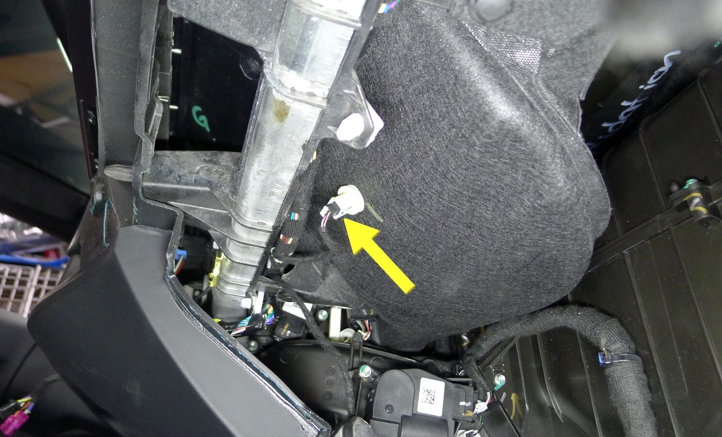
-
Install RH footrest panel
注Rotate RH footrest panel onto vehicle, Fold RH primary support carpet down
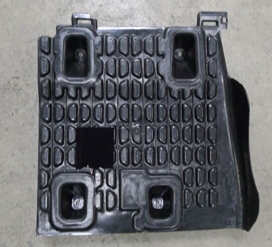
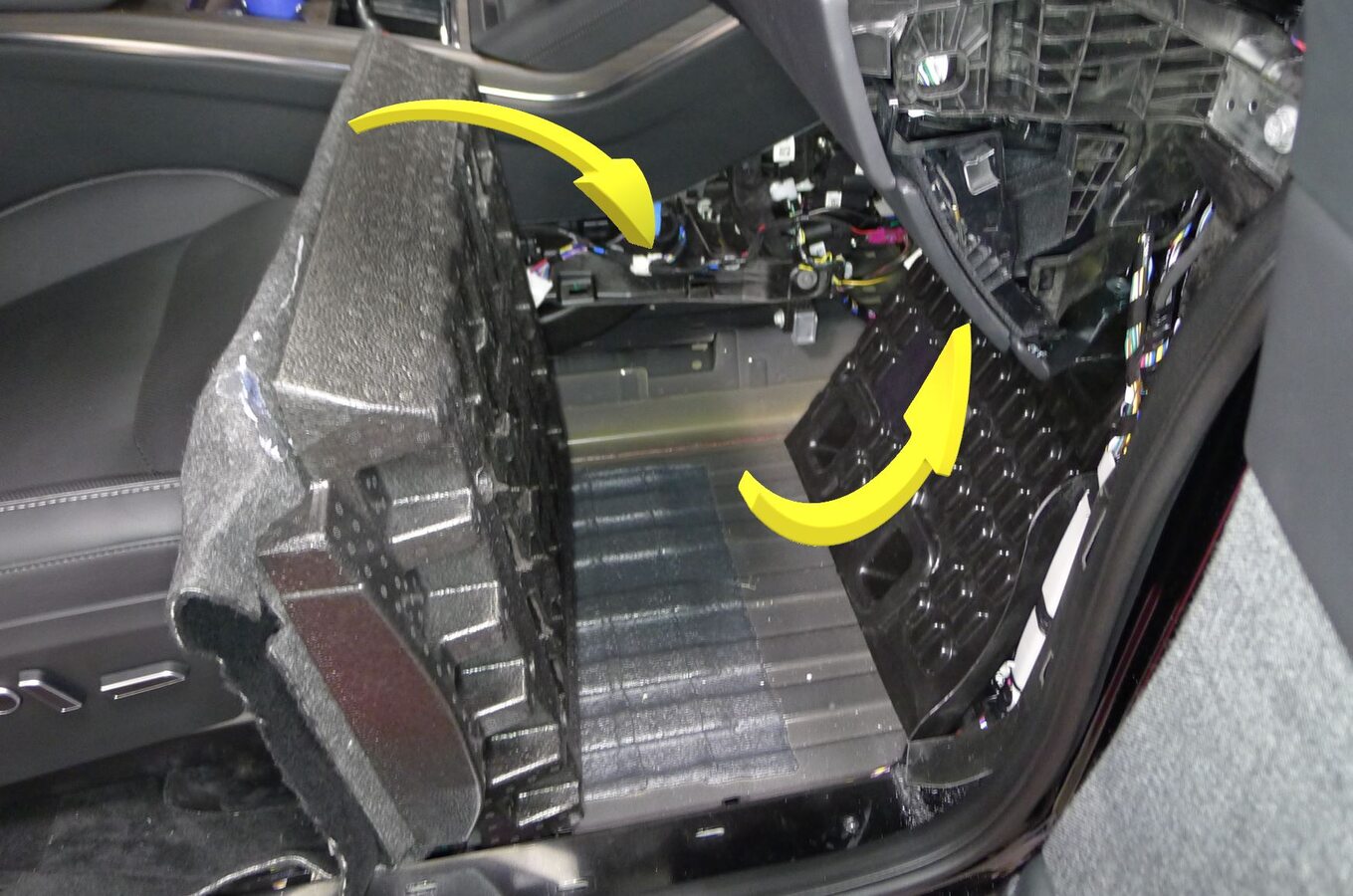
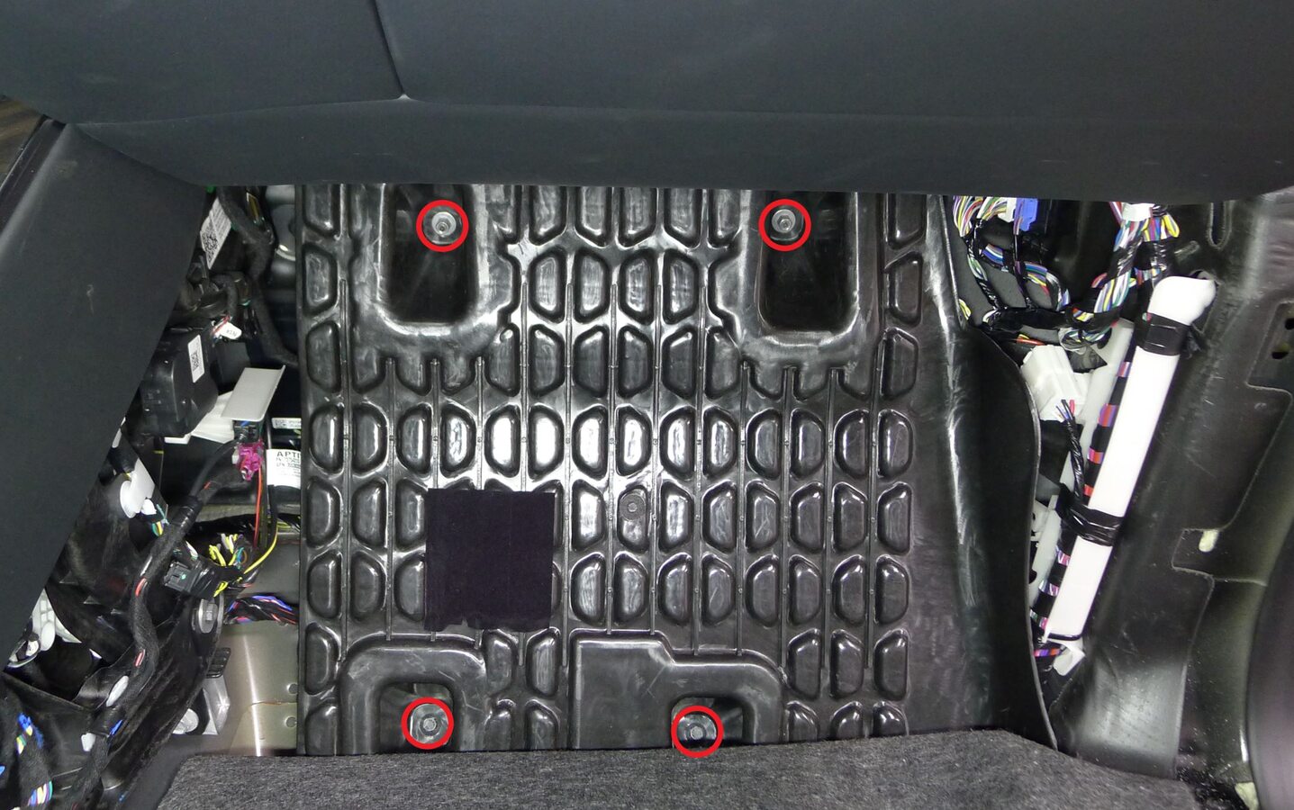
-
Secure RH footrest panel
注2x bolts, 10mm, 5 Nm, 2x nut, 10mm, 5 Nm
-
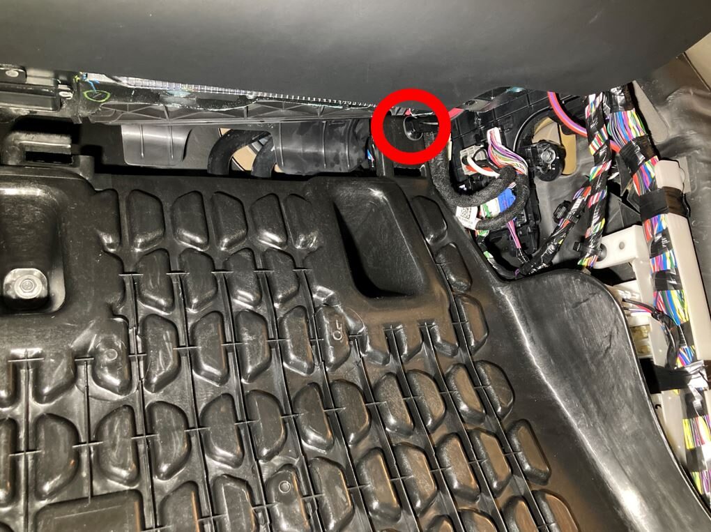
Secure harness to RH footrest panel
注1x clip
-
Fold RH main carpet back into place

-
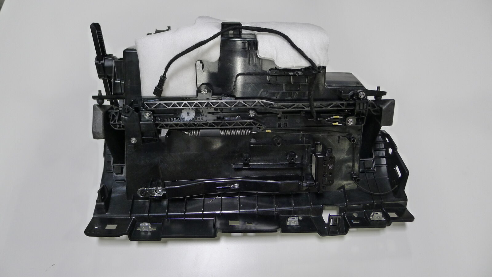
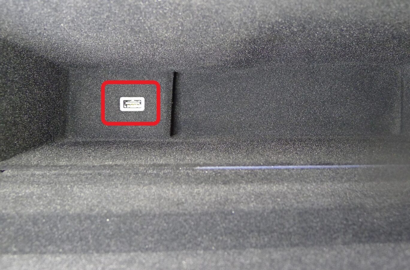
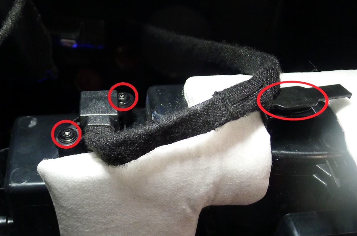
Secure USB outlet
注2x screws, T20, 2 Nm, 1x clip, Ensure USB socket flush in glove box
-
Secure glove box connectors
注3x connectors, Route harness through glove box datums

-
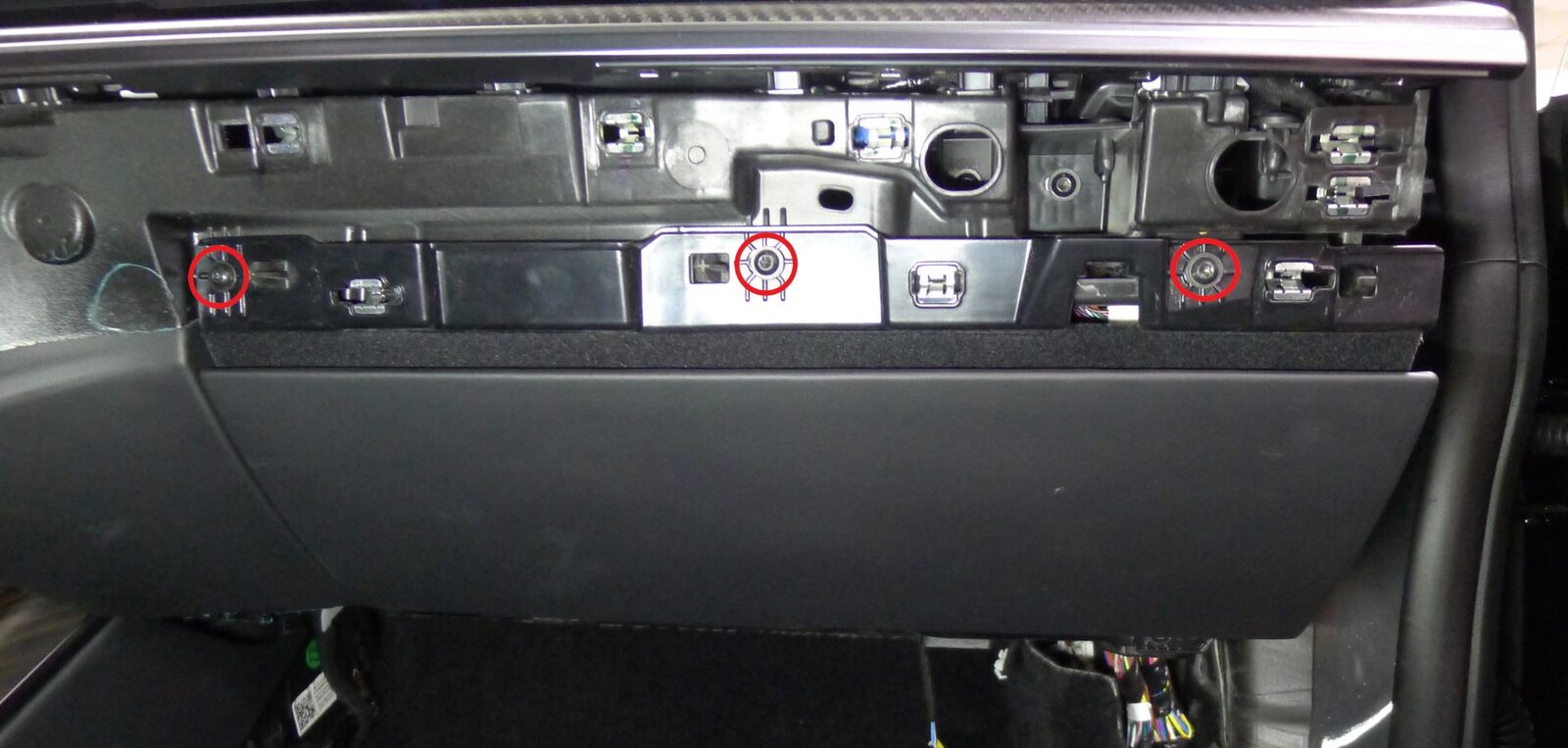
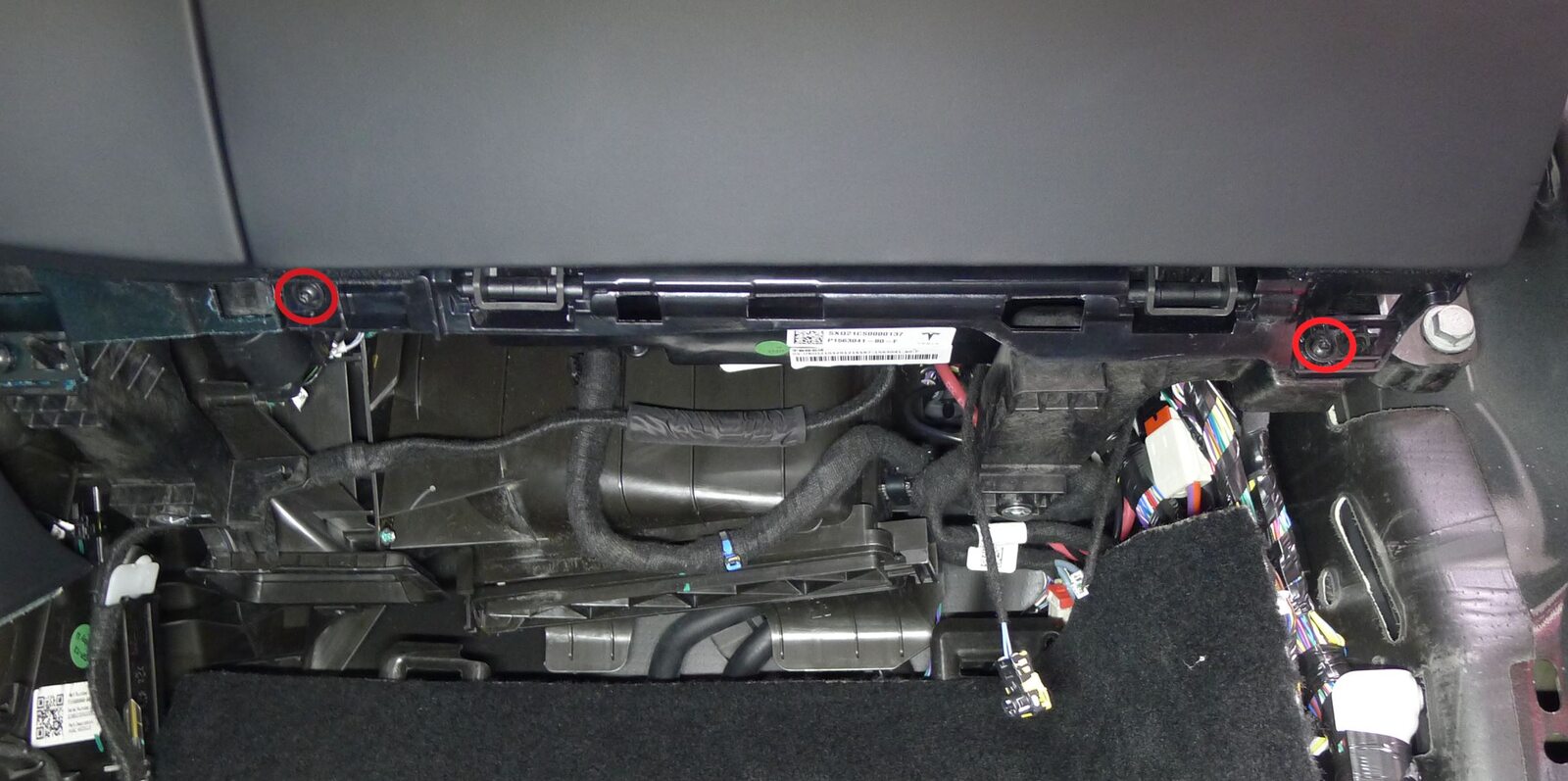
Install glove box
注5x screws, T20, 3 Nm
-
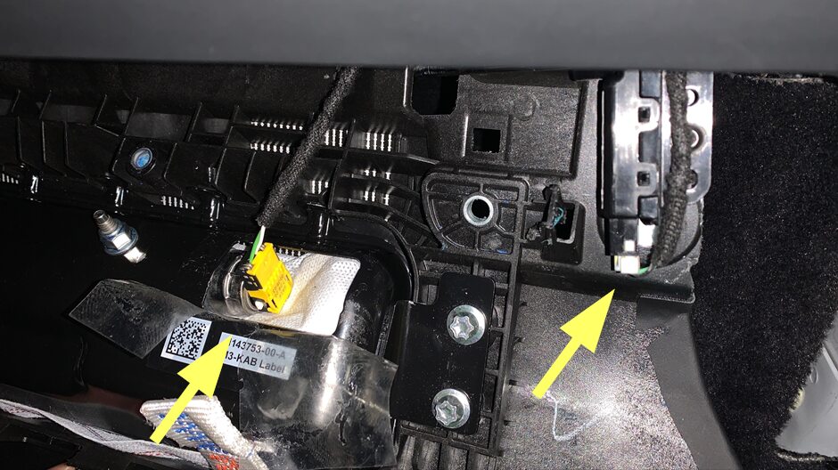
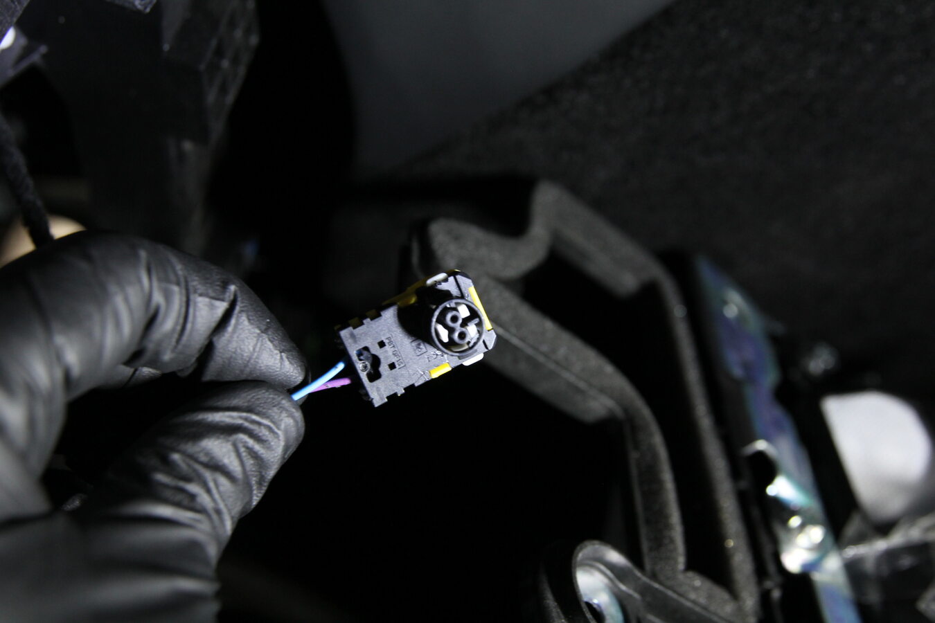
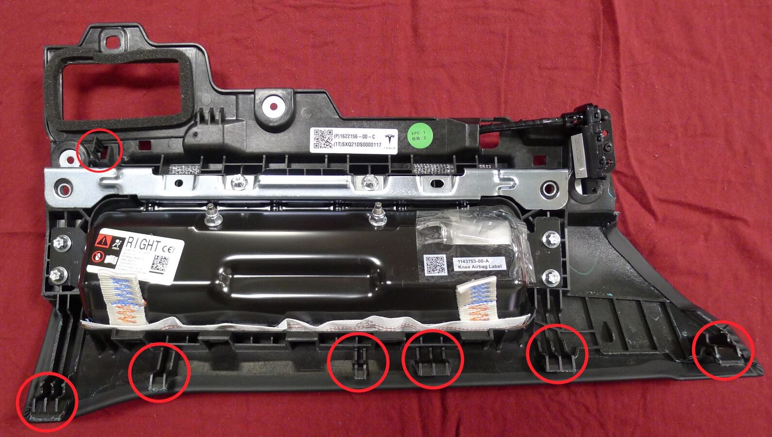
Install RH knee air bag assembly onto vehicle
注2x connectors, 6x tabs, 1x clip, Hook tabs before fully seating, Use caution not to damage the connector/harness, Support the knee air bag while connecting the connector
-
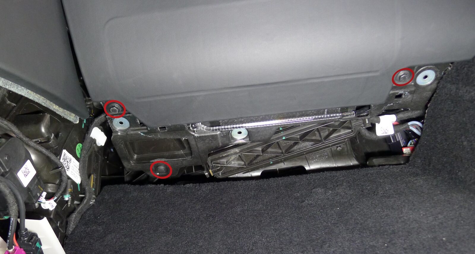
Install fasteners securing RH knee air bag assembly to vehicle
注2x bolts, 10mm, 8 Nm, 1x clip
-
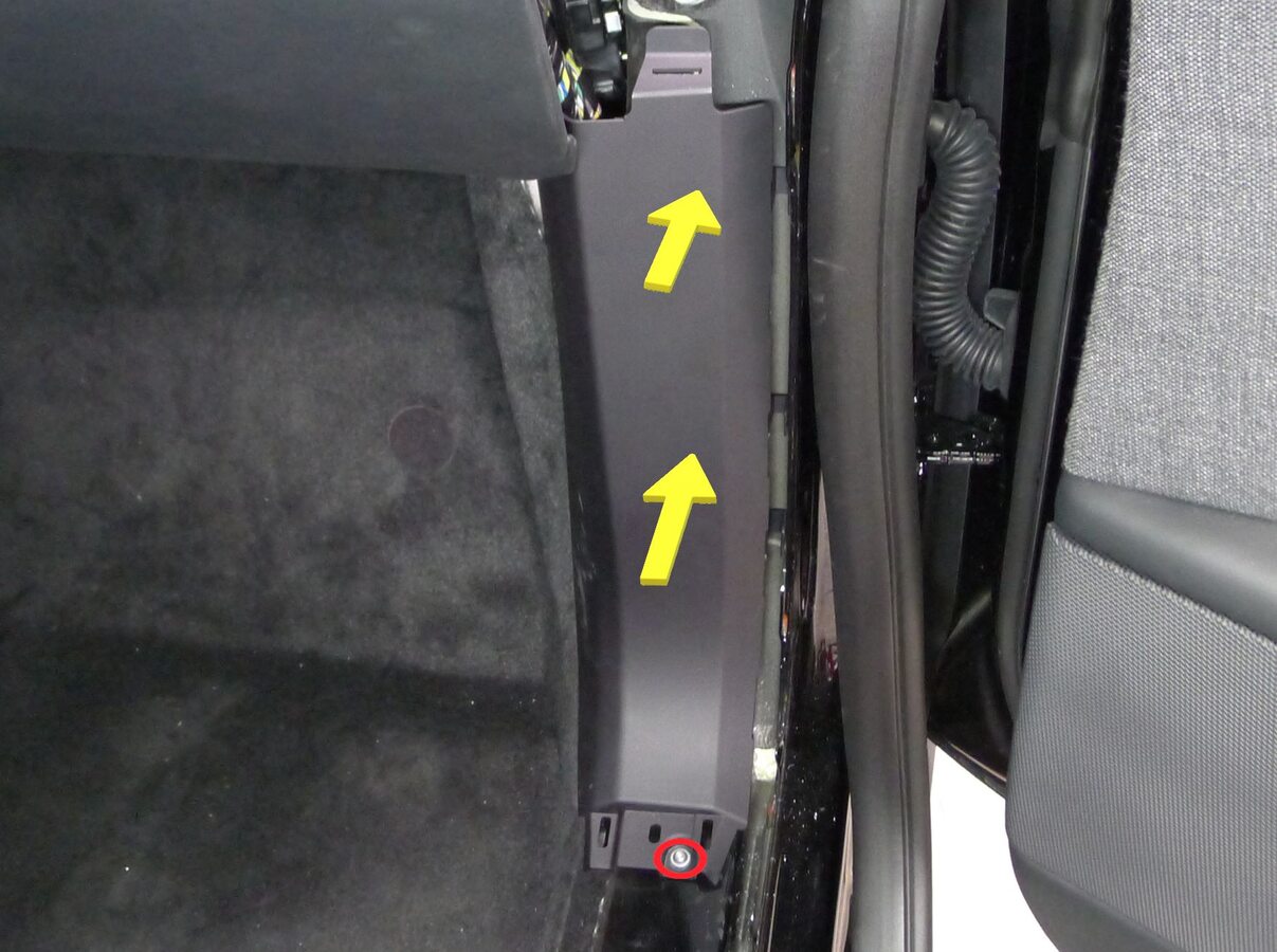
Install RH lower A-pillar trim
注1x bolt, T25, 5 Nm, 2x clips, 1x datum

-
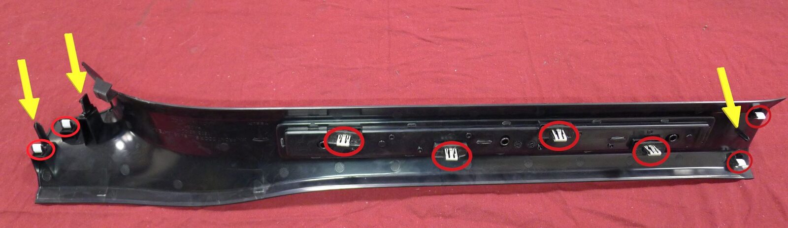
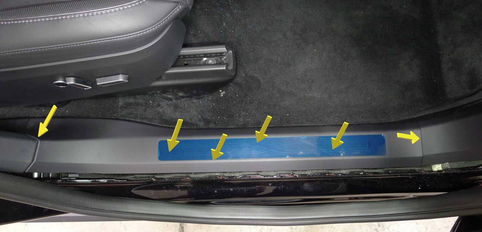
Install RH front door sill trim panel
注8x clips, 3x datums
-
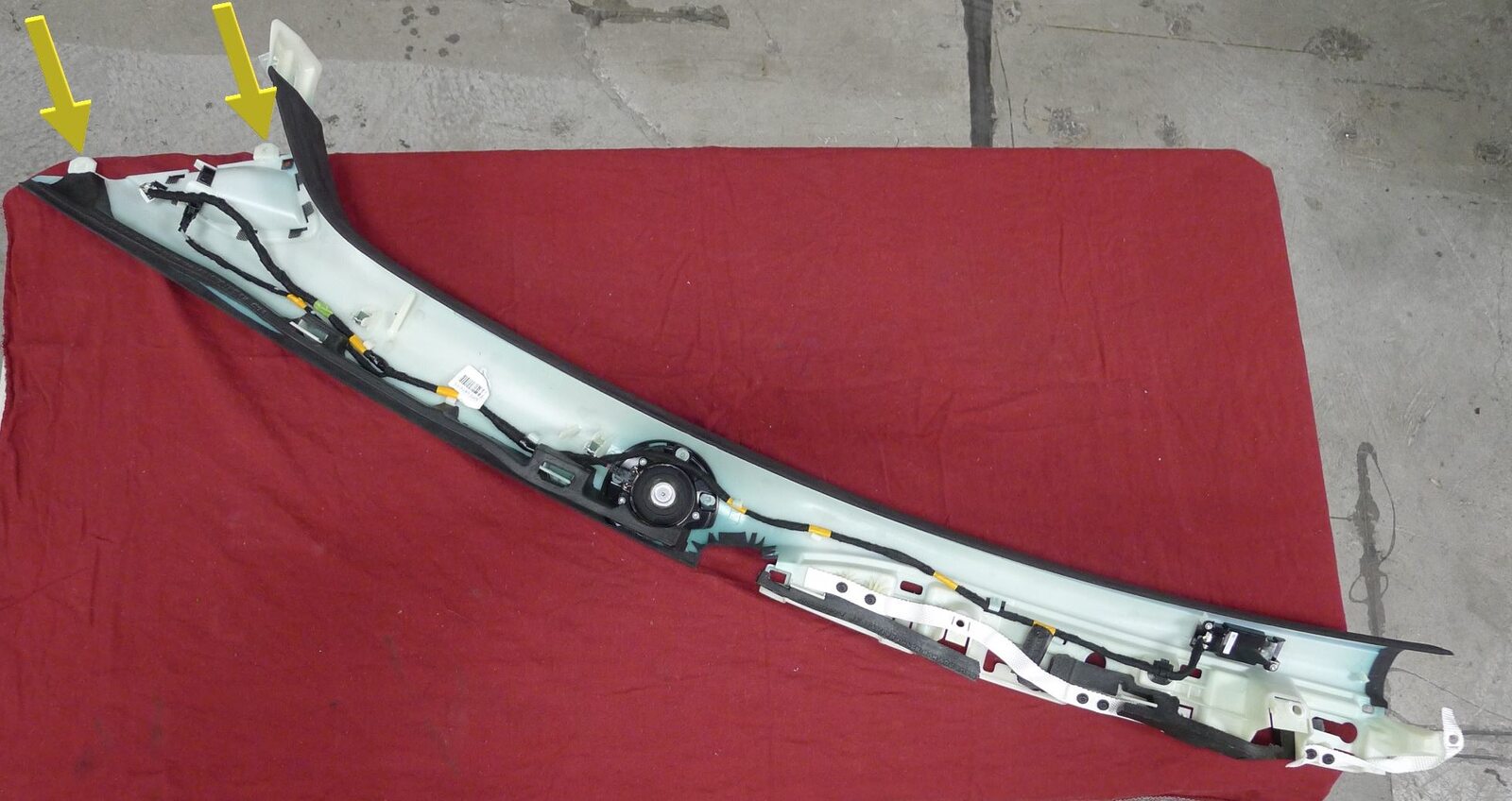
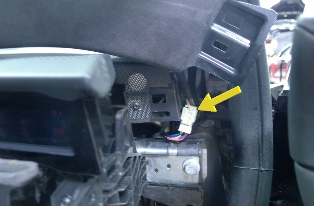
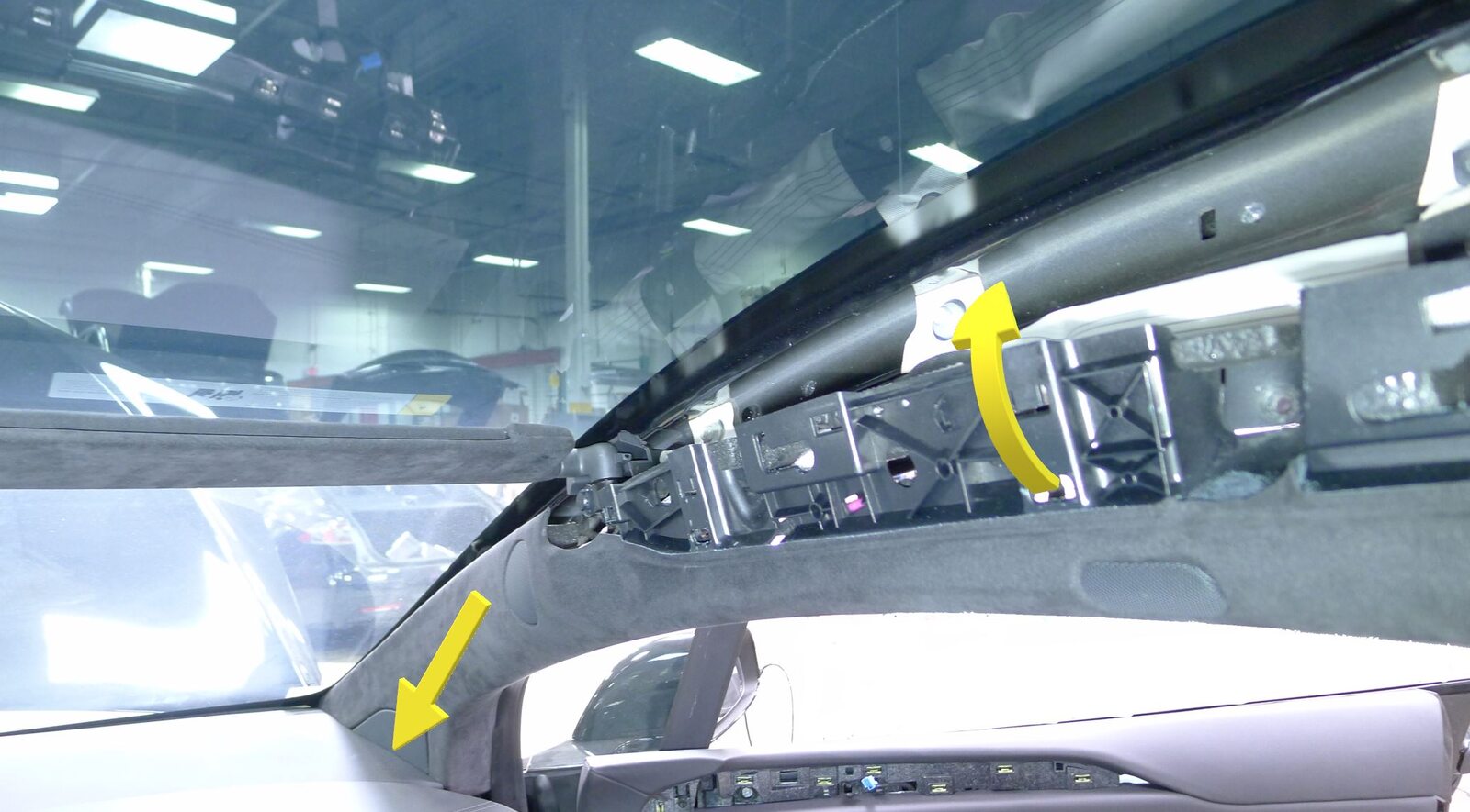
Position RH upper A-pillar to vehicle
注1x connector, 2x datums, Secure RH upper A-pillar harness, Align datums into IP sub assembly, Rotate upper A-pillar panel into position
-
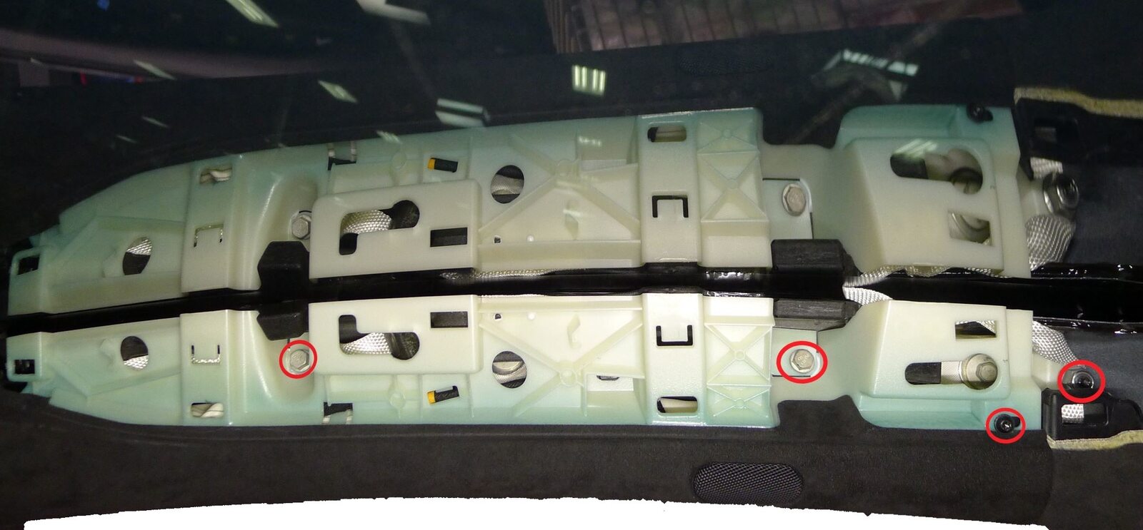
Secure RH upper A-pillar to body
注2x bolts, 10mm, 5 Nm, 1x screw, T20, 2.5 Nm, 1x nyloc nut, 13mm, 5 Nm, Install new nut
-
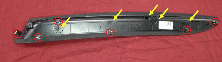
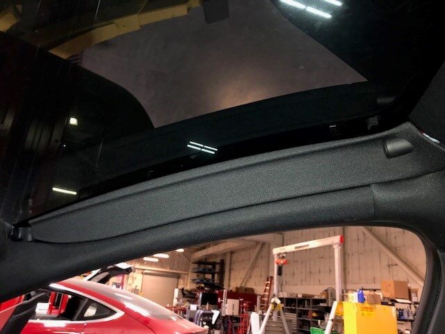
Install RH sun visor bezel
注6x clips, 1x tab, Insert tab and slide bezel towards rear of vehicle, then secure clips
-
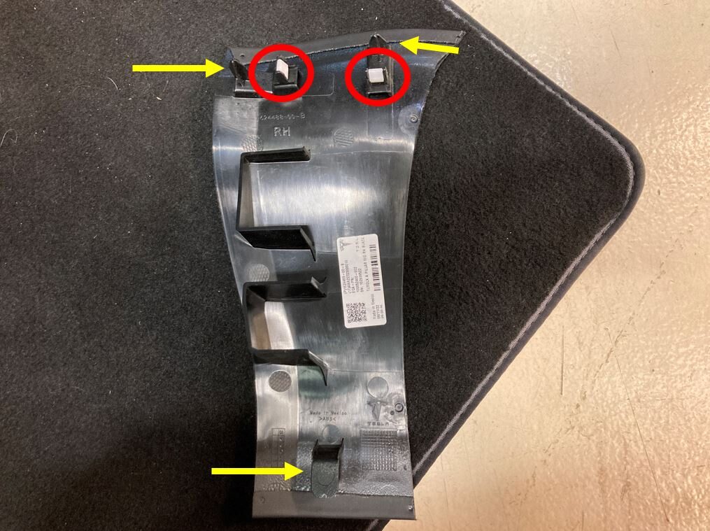
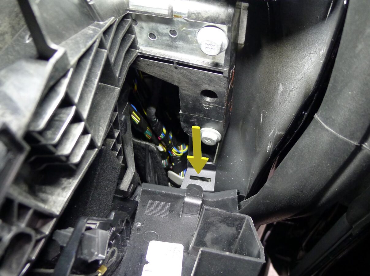
Install RH mid A-pillar trim
注2x clips, 3x datums, Verify weather seal is seated properly
-
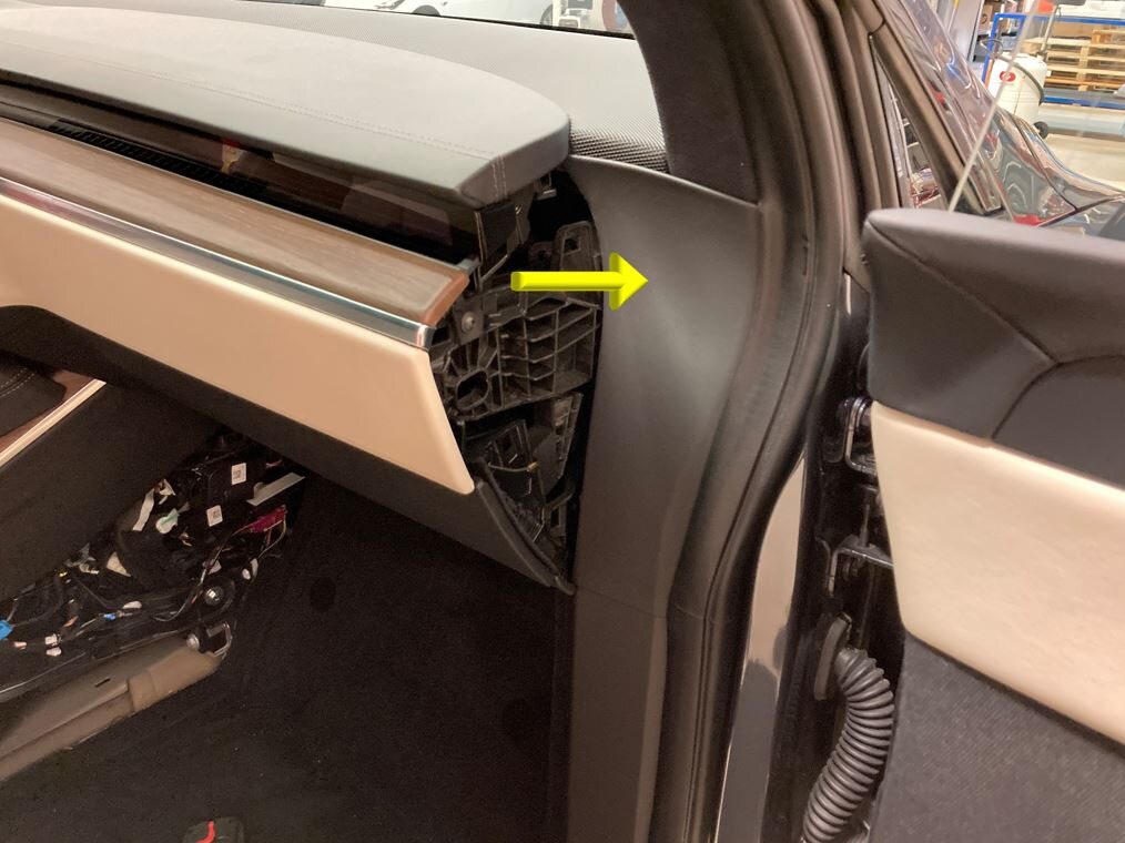
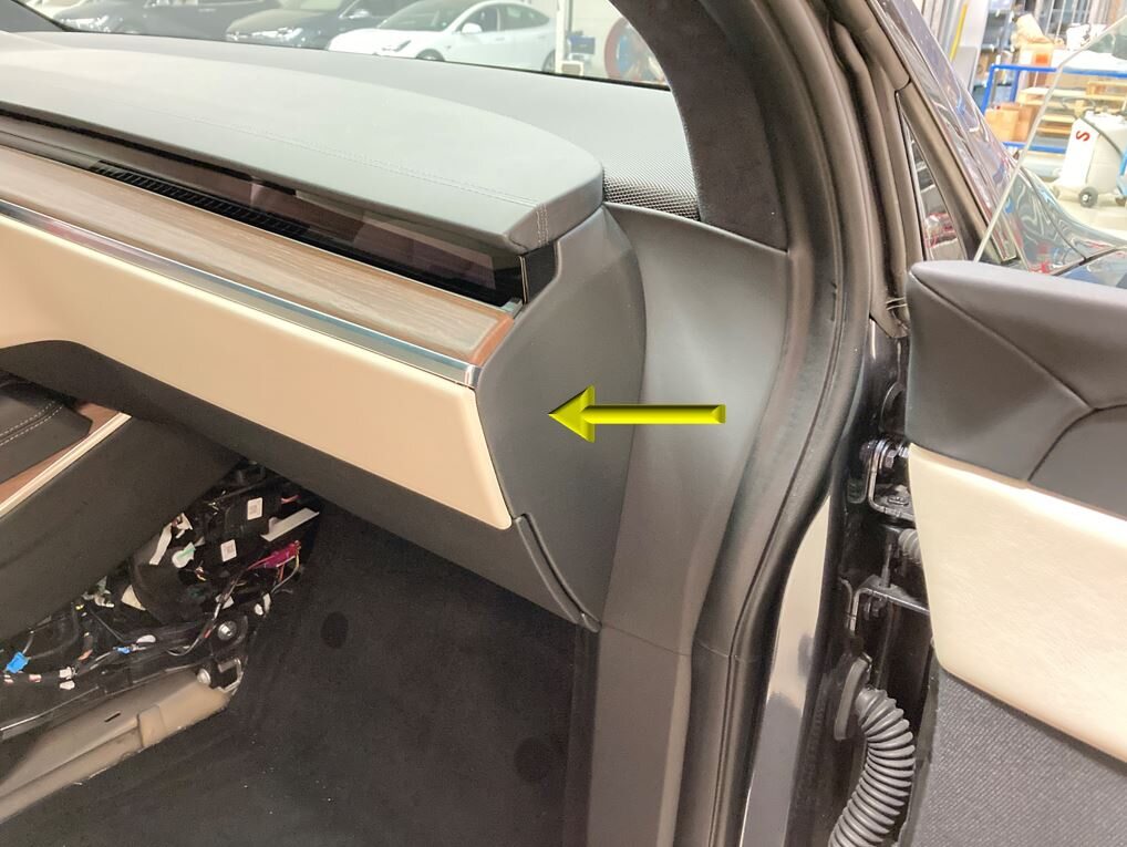
Install RH IP end cap
注3x clips
-
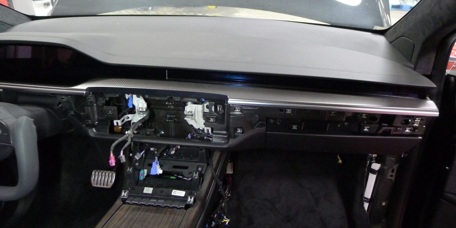
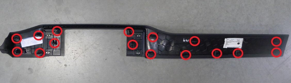
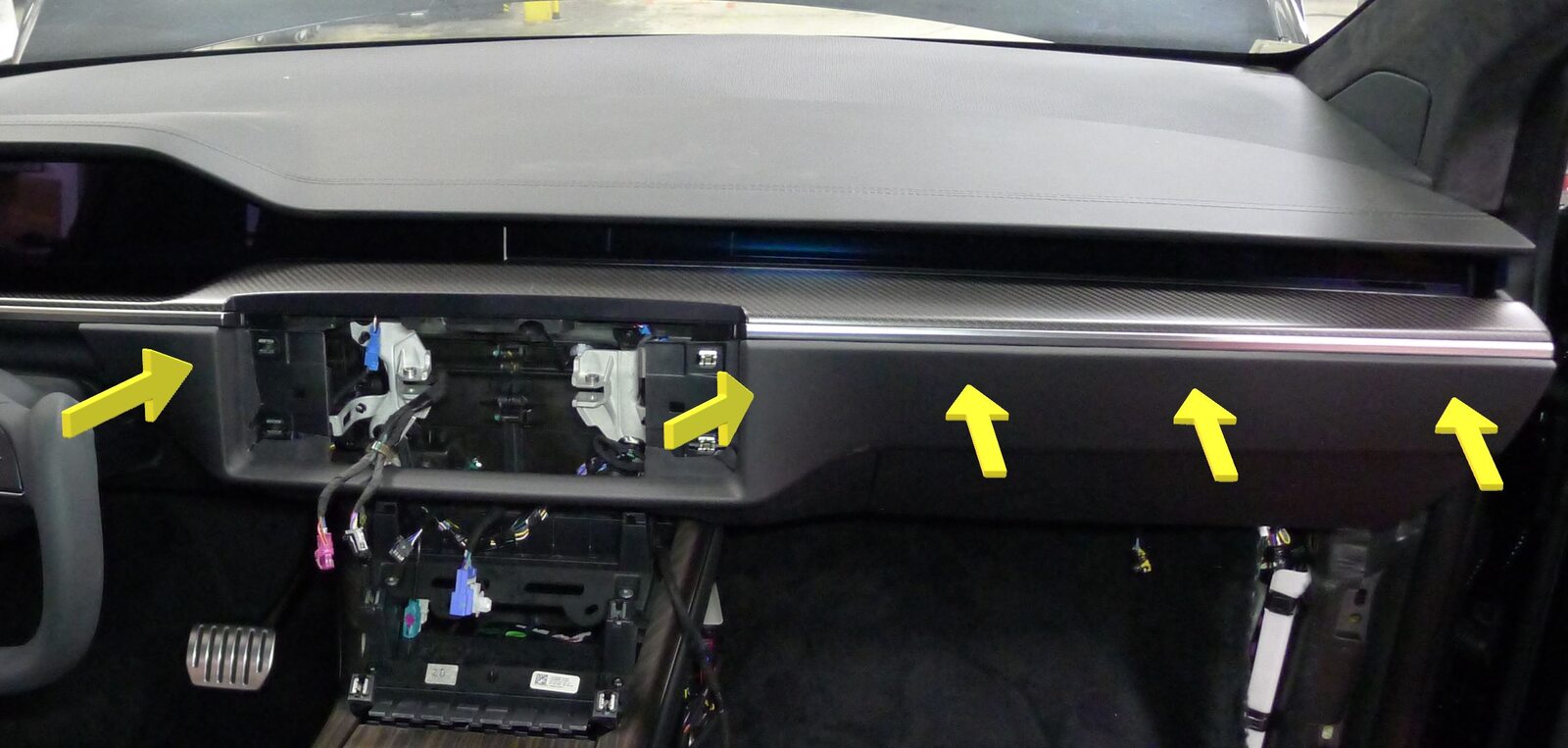
Install IP RH mid Panel
注14x tabs, 2 datums
-
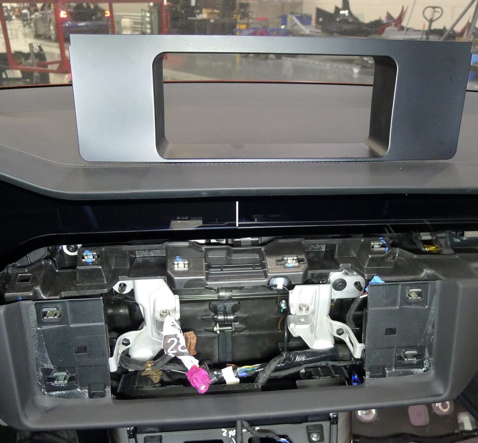
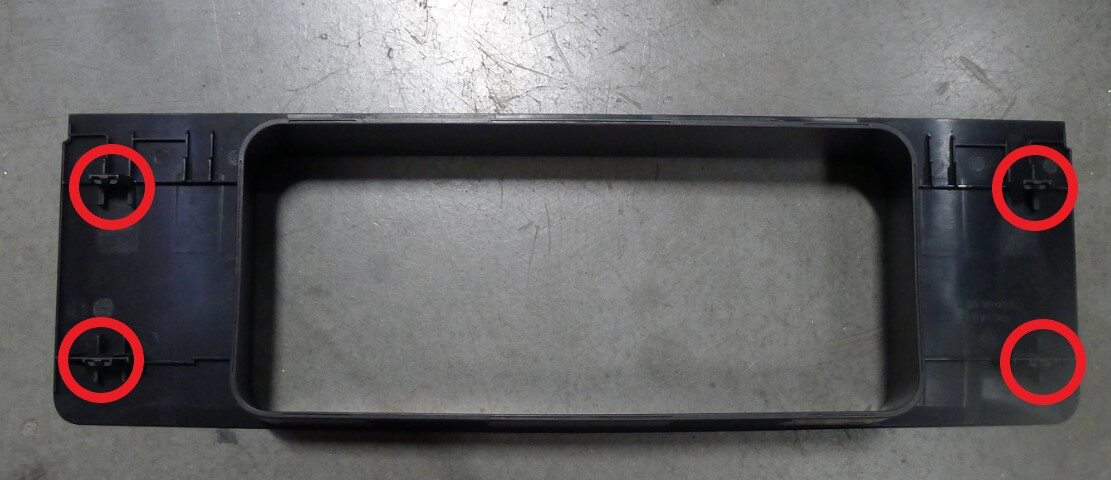
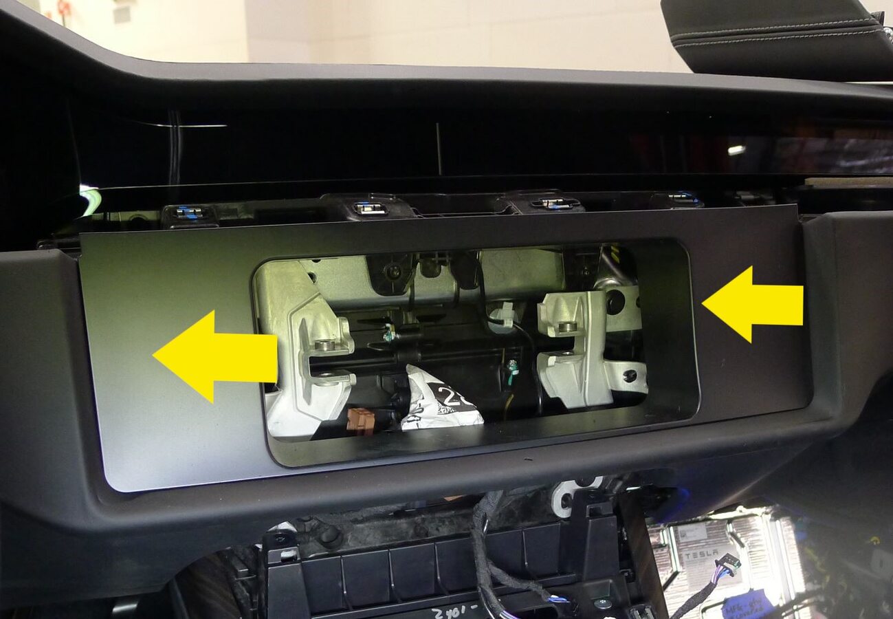
Install IP closeout panel
注4x tabs
-
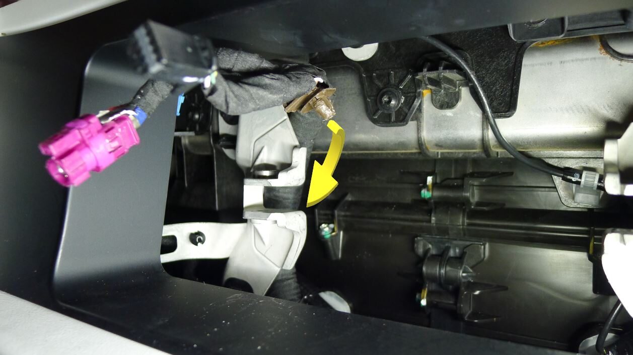
Route display harness behind LH display bracket
-
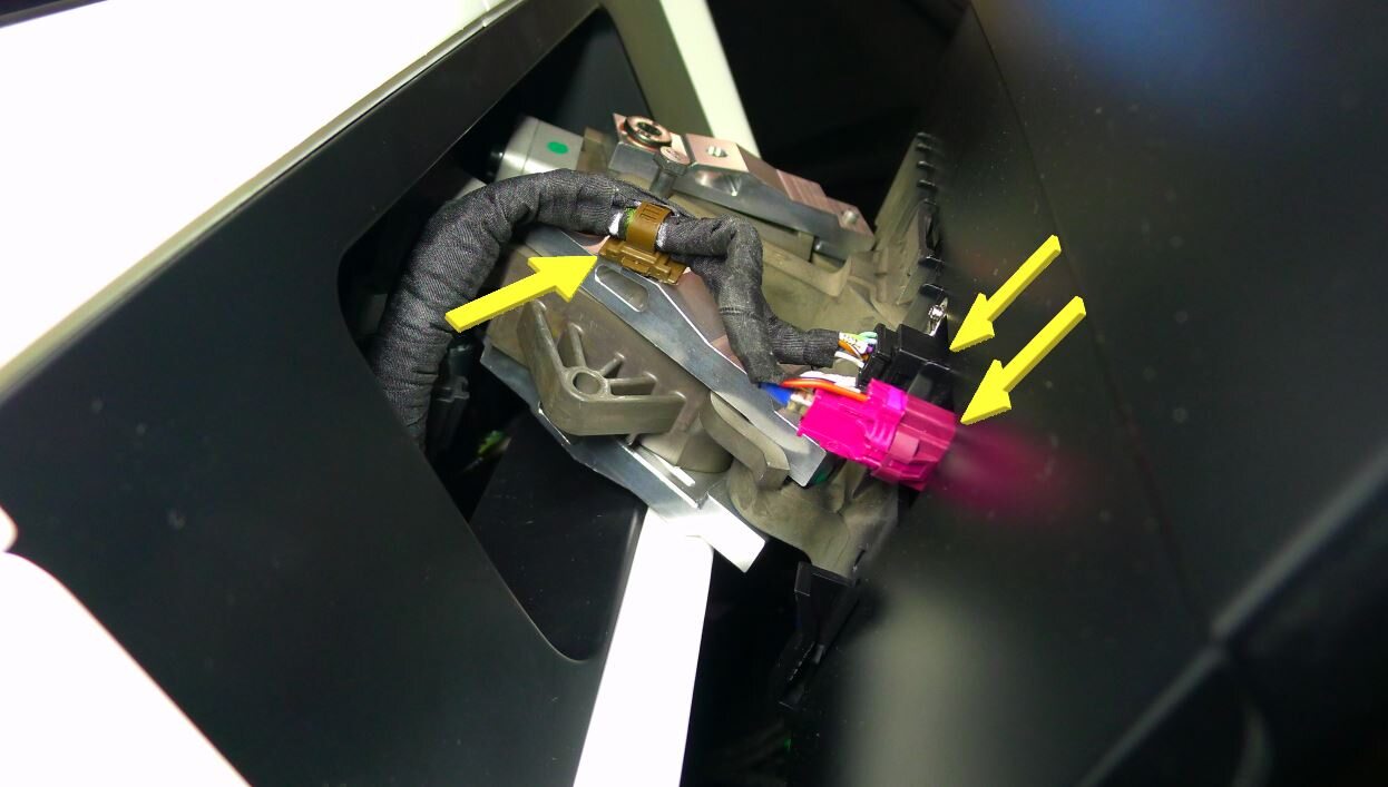
Secure center display coax and power connectors
注2x connectors, 1x clip, Ensure strain relief clip is secure to linkage arm, Replace clip if damaged
-
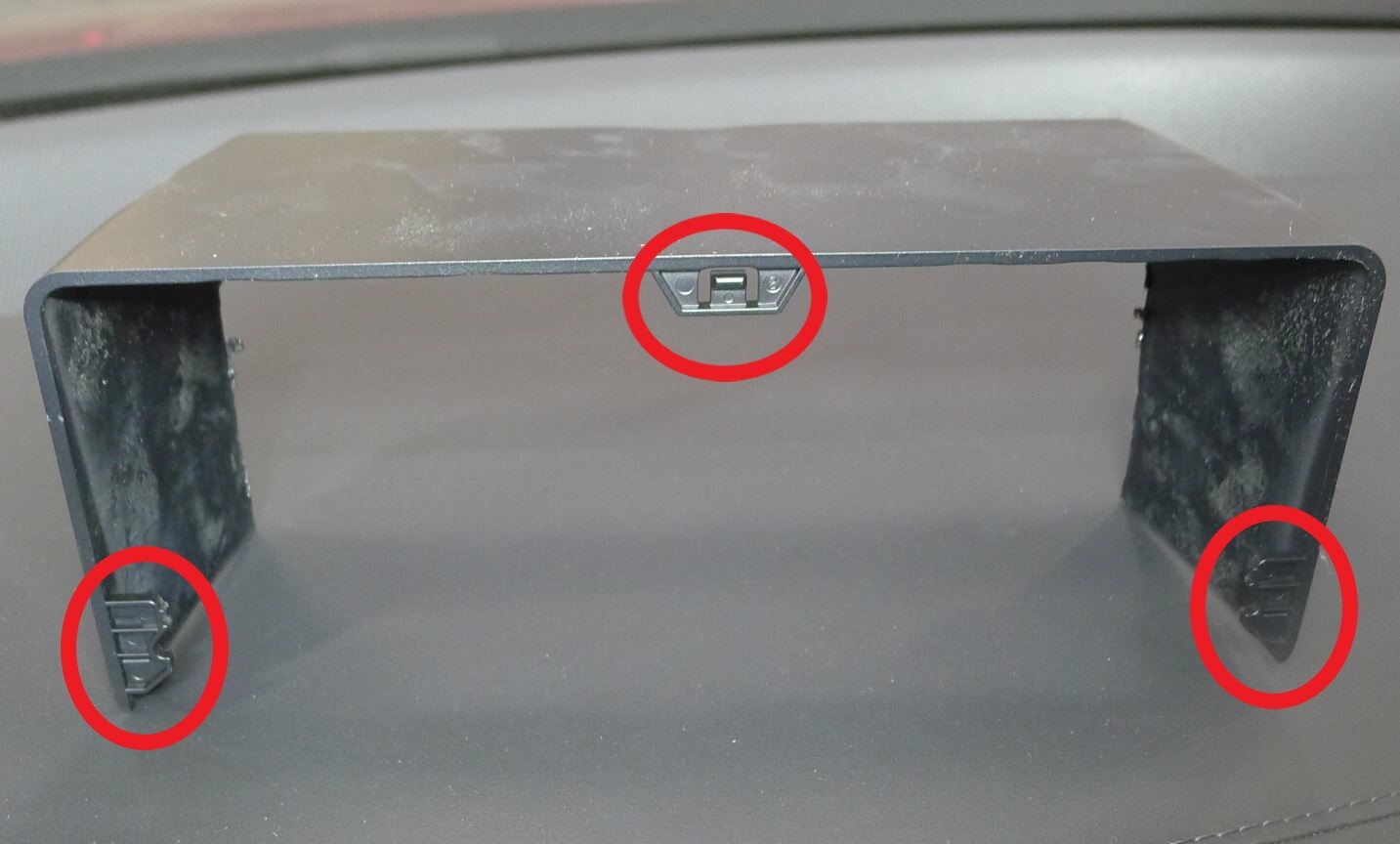
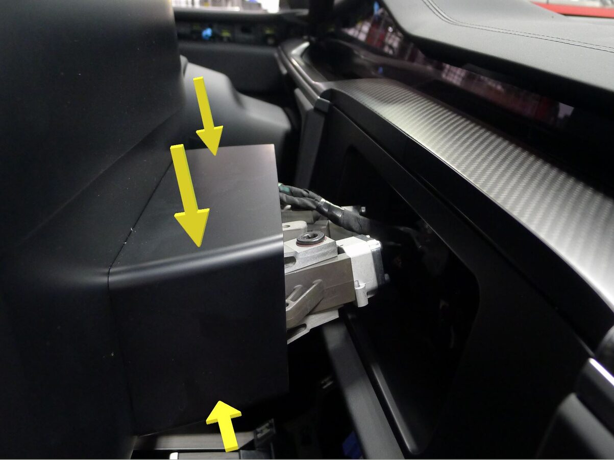
Install center display shroud
注3x tabs, Slide display downward until shroud tabs fully engages
-
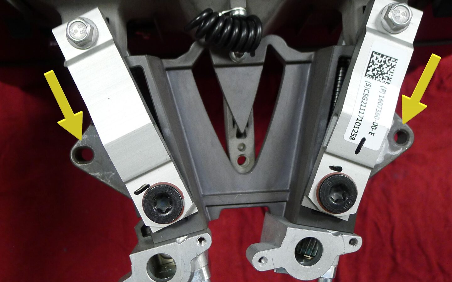
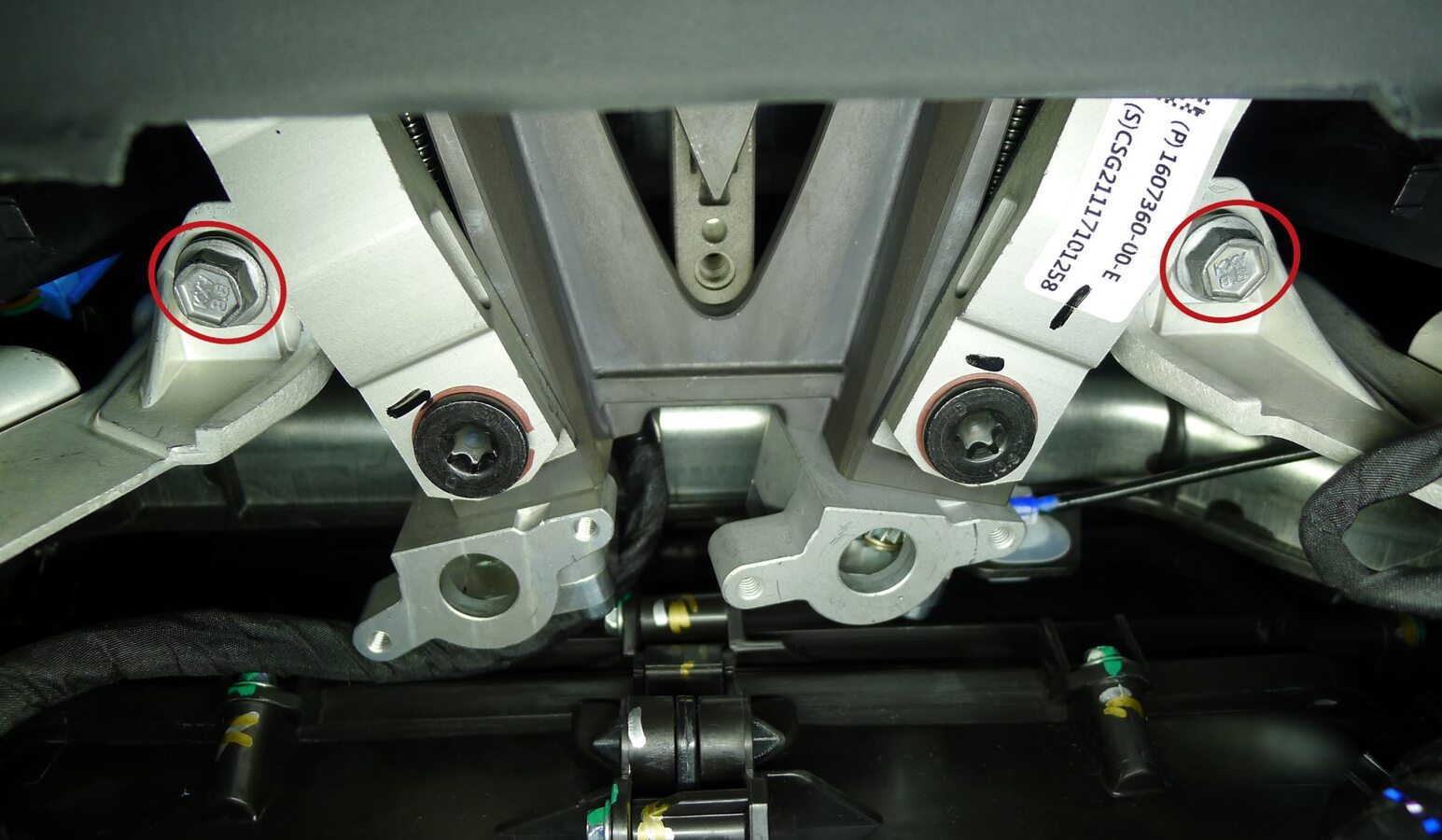
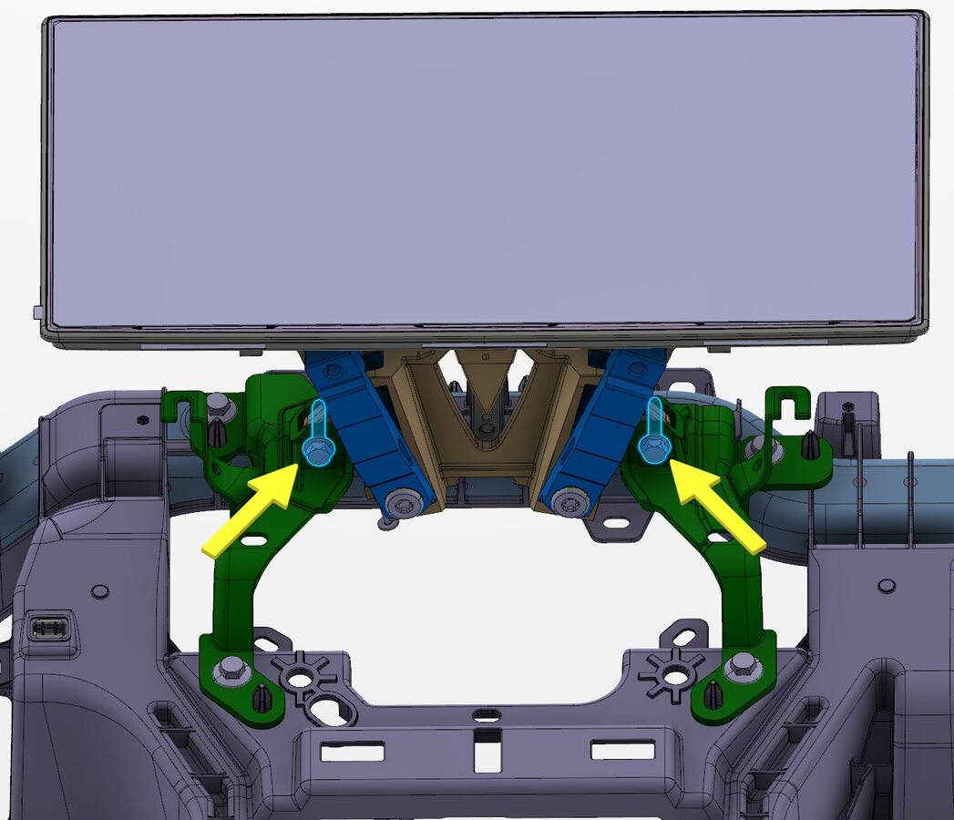
Secure center display to IP carrier
注2x bolts, 10mm, 11.5 Nm, Slide center display into IP carrier, Start RH bolt first
-
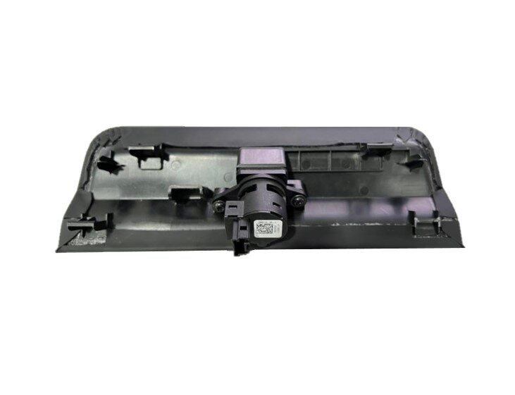
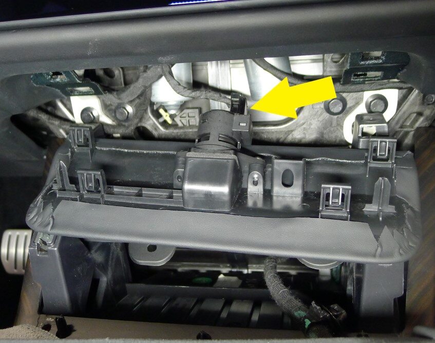
Secure IP service panel connector
注1x connector
-
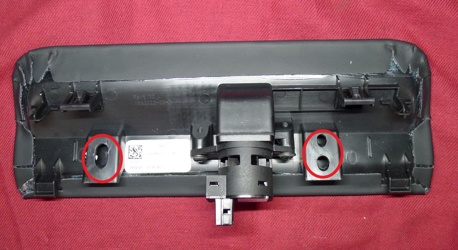
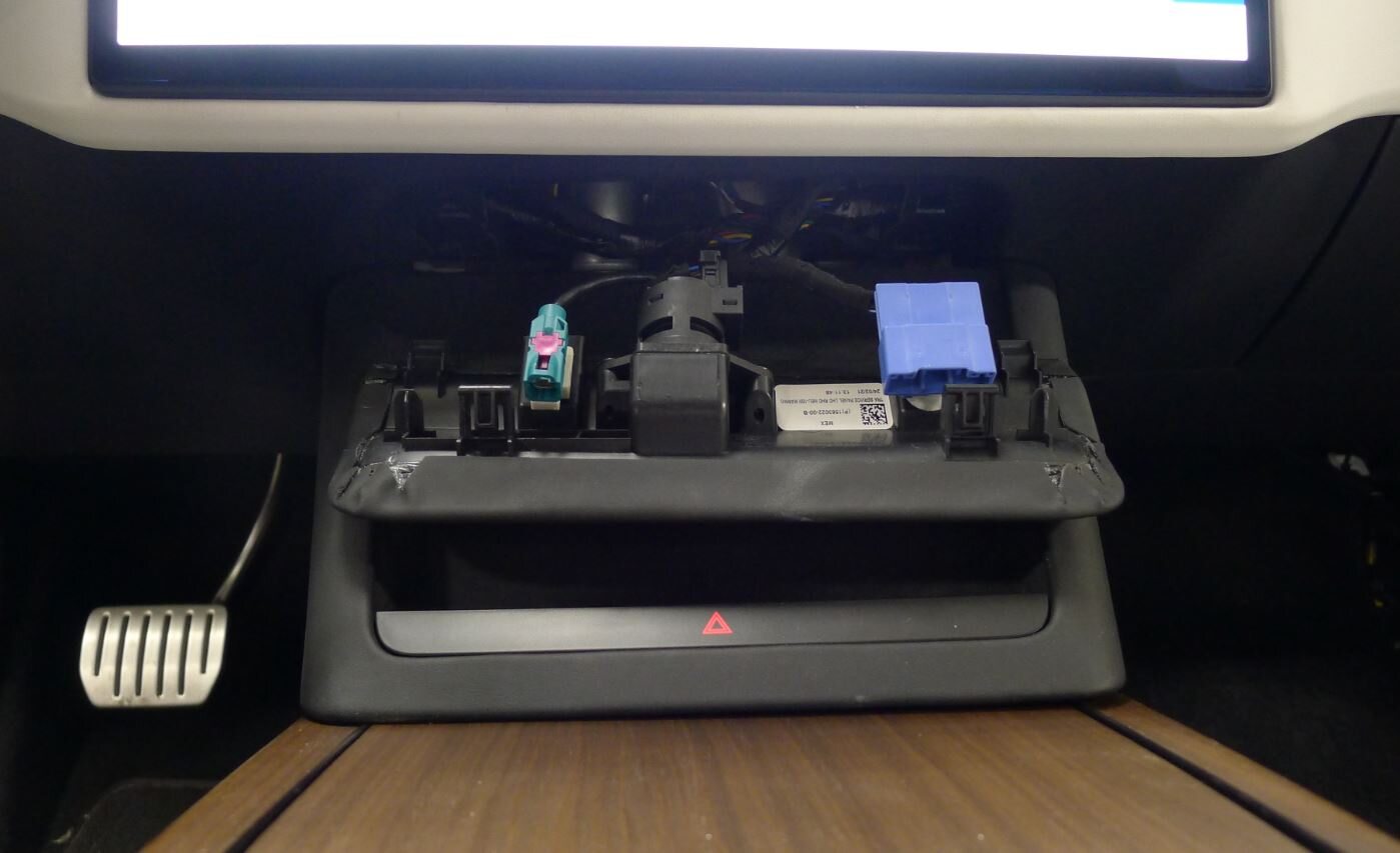
Secure diagnostic and CAN harnesses to IP service panel
注2x clips

-
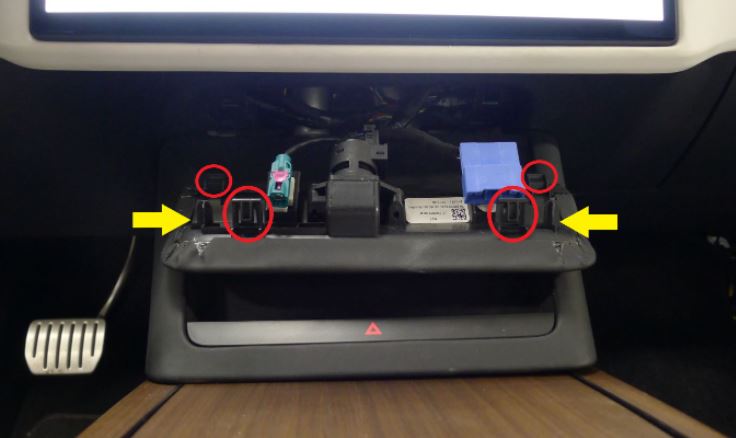
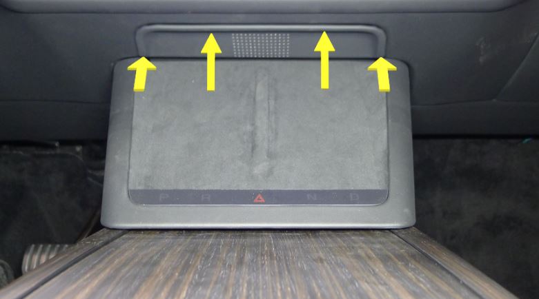
Install the IP service panel.
-
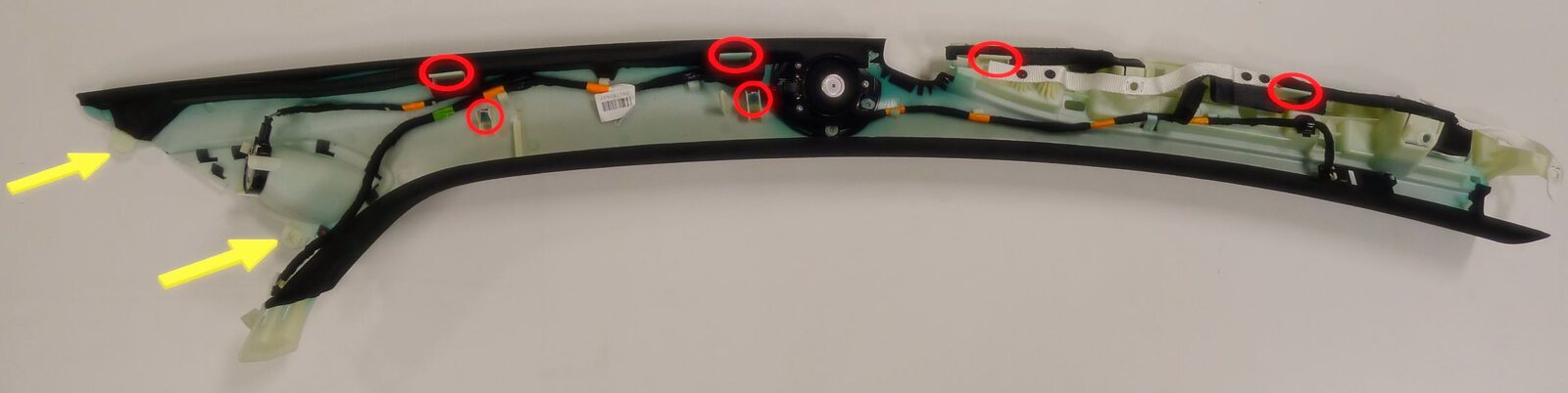
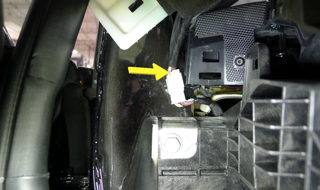
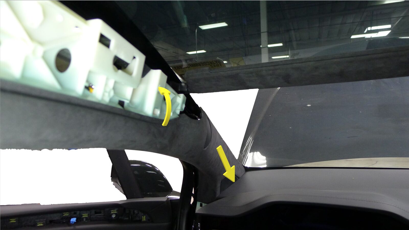
Position LH upper A-pillar to vehicle
注1x connector, 2x datums, 6x clips, Secure LH upper A-pillar harness, Align datums into IP sub assembly, Rotate upper A-pillar panel into position engaging clips fully
-
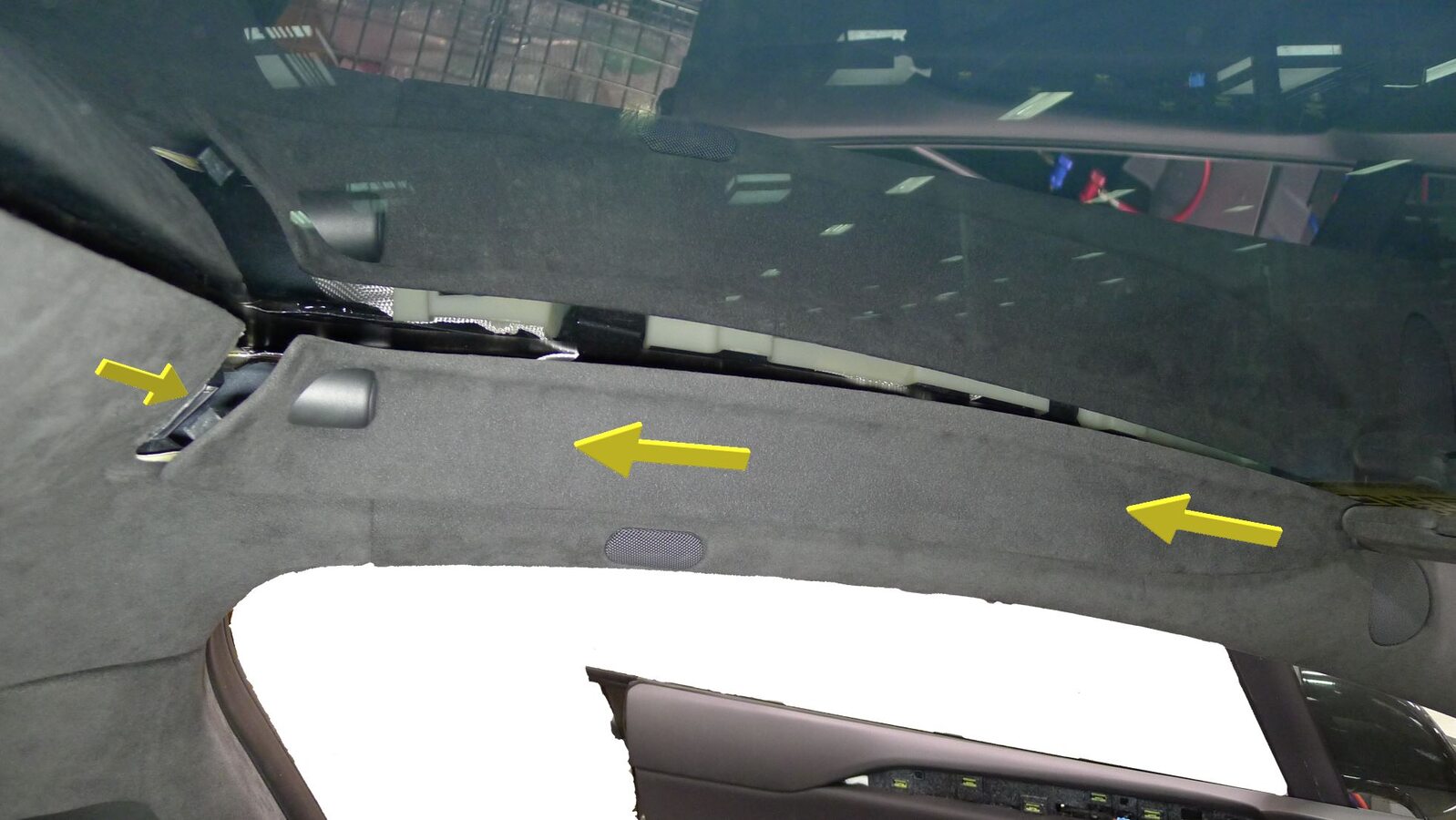
Install LH sun visor bezel
注6x clips, 5x tabs, Insert tabs and slide bezel towards rear of vehicle, then secure clips

-
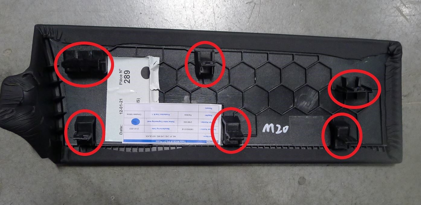
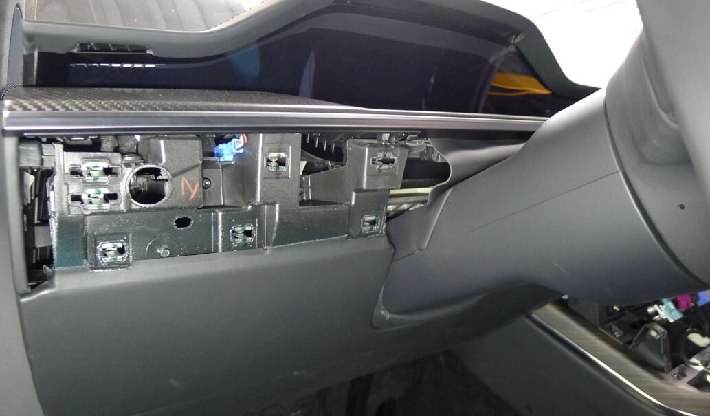
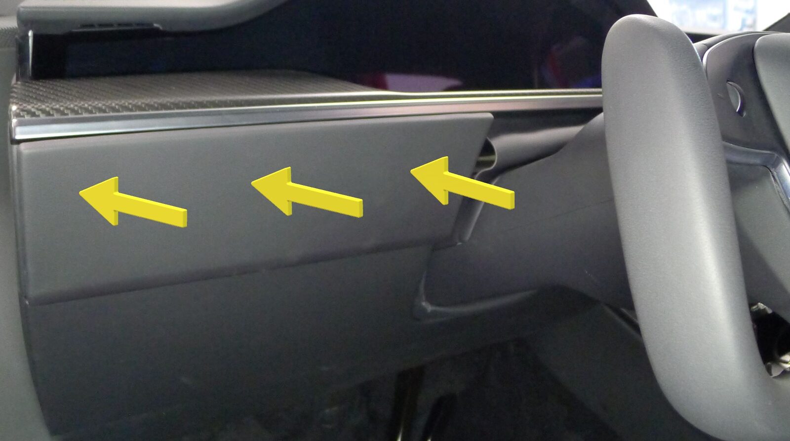
Install IP LH mid panel
注6x tabs
-
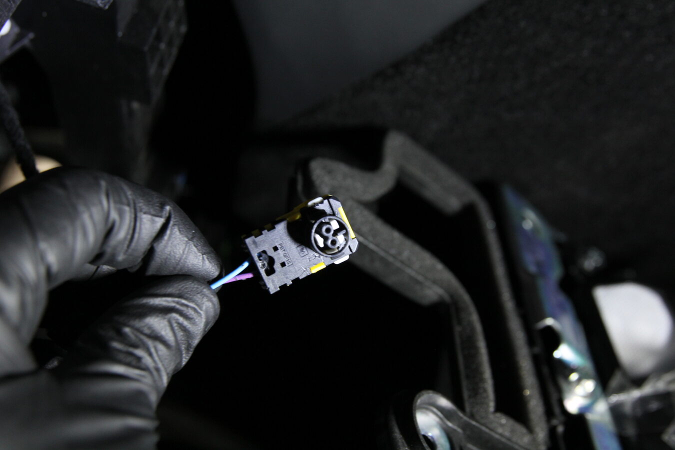
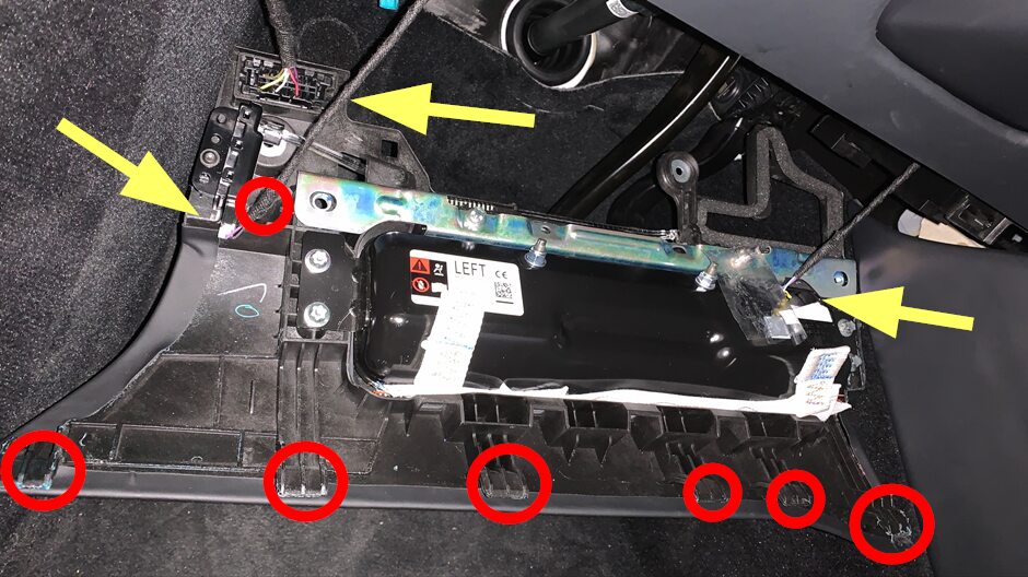
Install the LH knee air bag assembly into vehicle
注1x clip, 3x connectors, 6x tabs, Hook tabs before fully seating, Use caution not to damage the connector/harness, Support the knee air bag while connecting the connectors
-
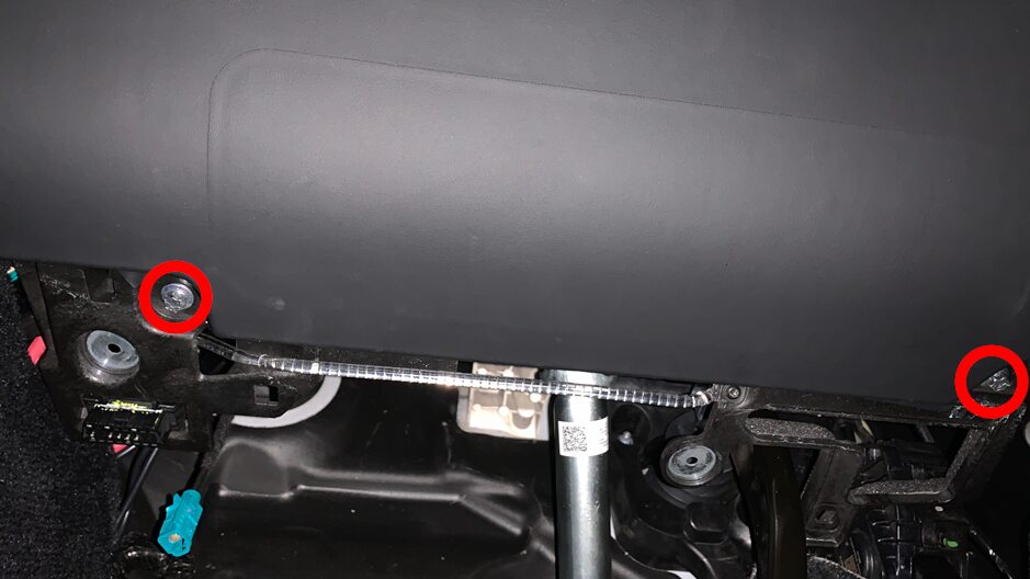
Install fasteners securing LH knee air bag assembly to vehicle
注2x patch bolts, E10, 8 Nm, Install new fasteners
-
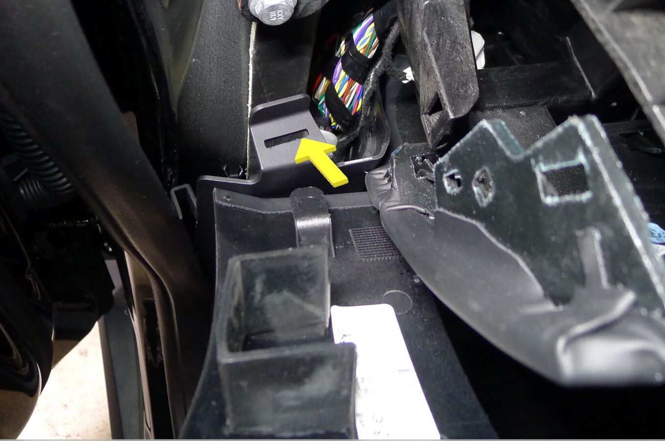
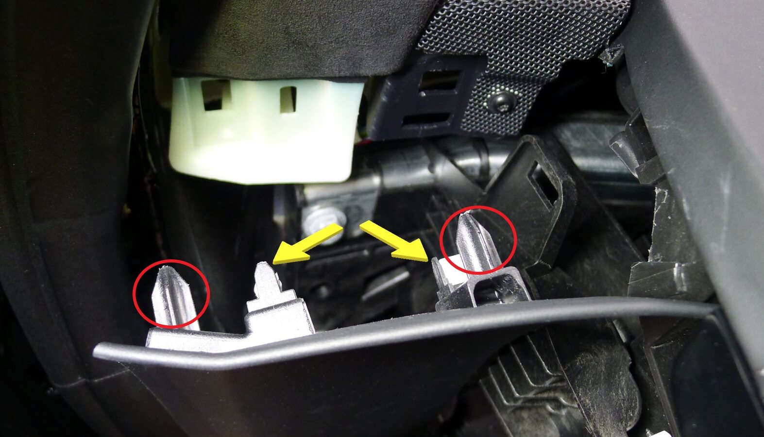
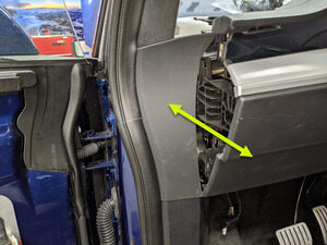
Install LH mid A-pillar trim
注2x clips, 3x datums, Insert mid A-pillar trim into lower A-pillar trim, Secure clips into upper A-pillar and IP sub assembly, Verify weather seal is seated properly
-
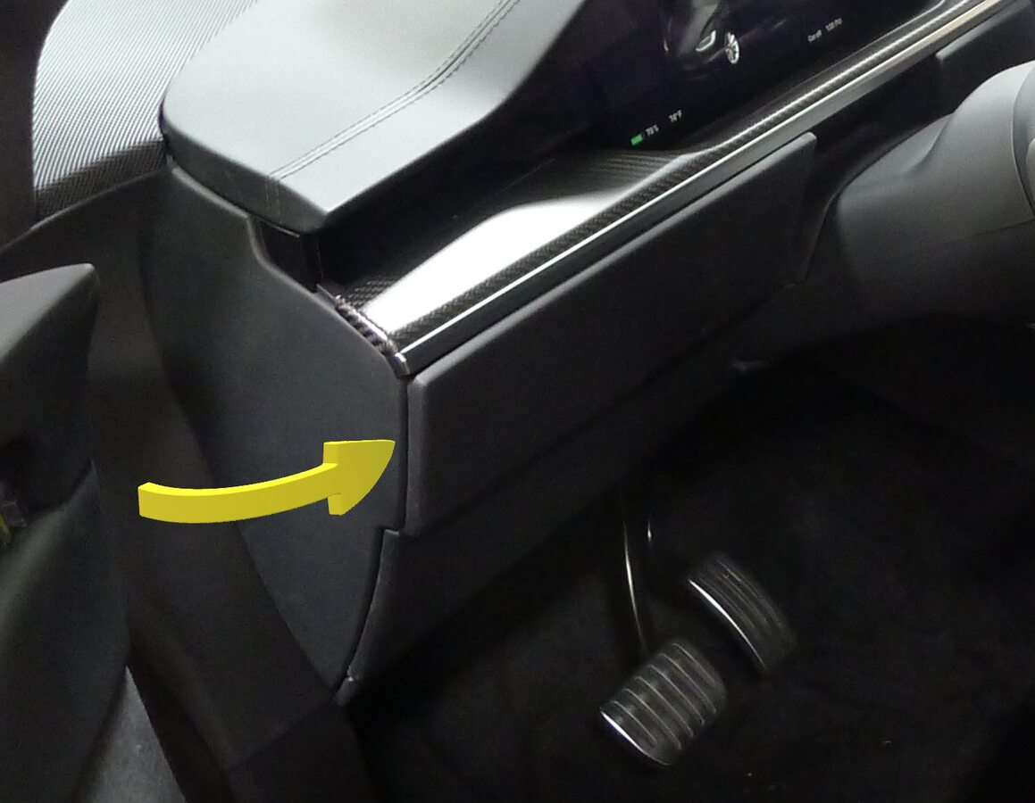
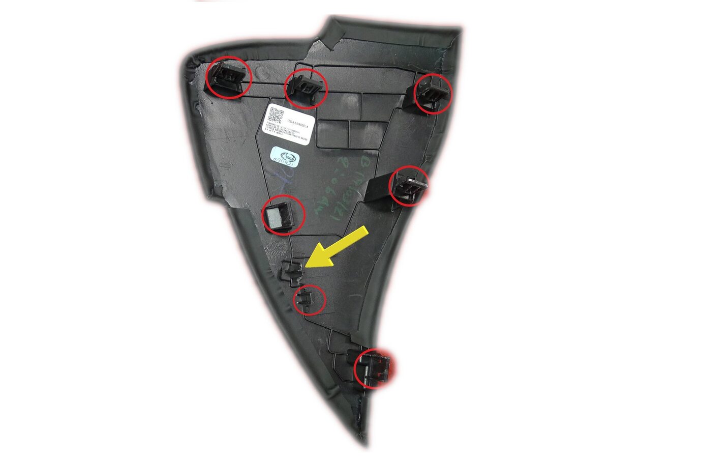
Install LH IP end cap
注7x clips, 1x datum
-
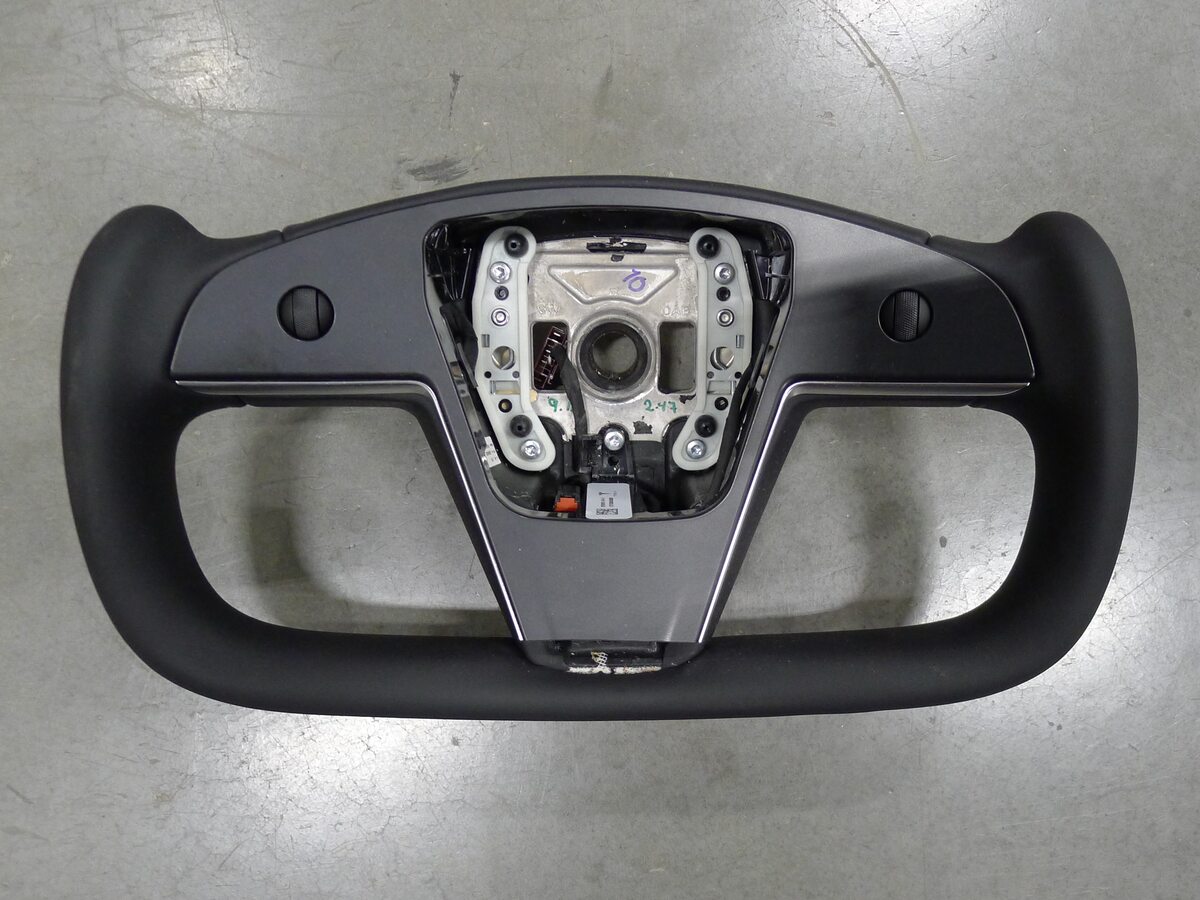
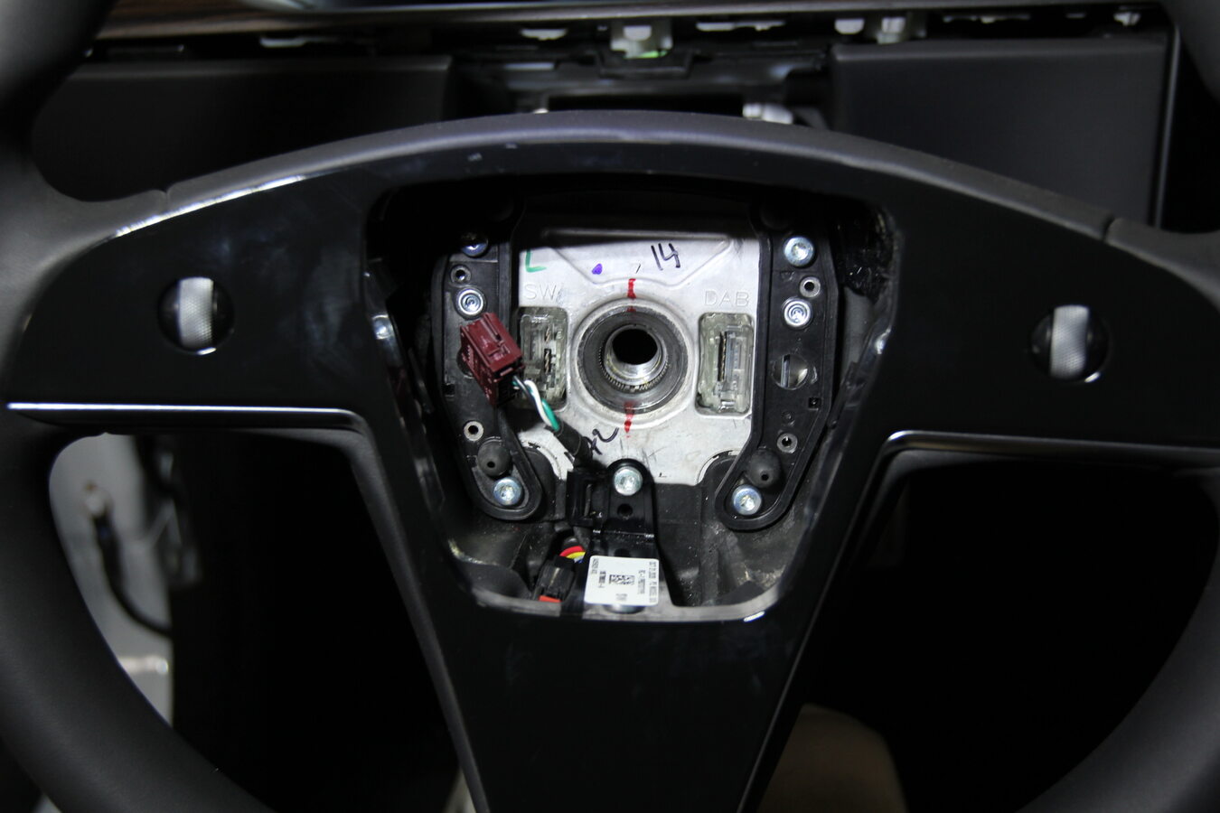
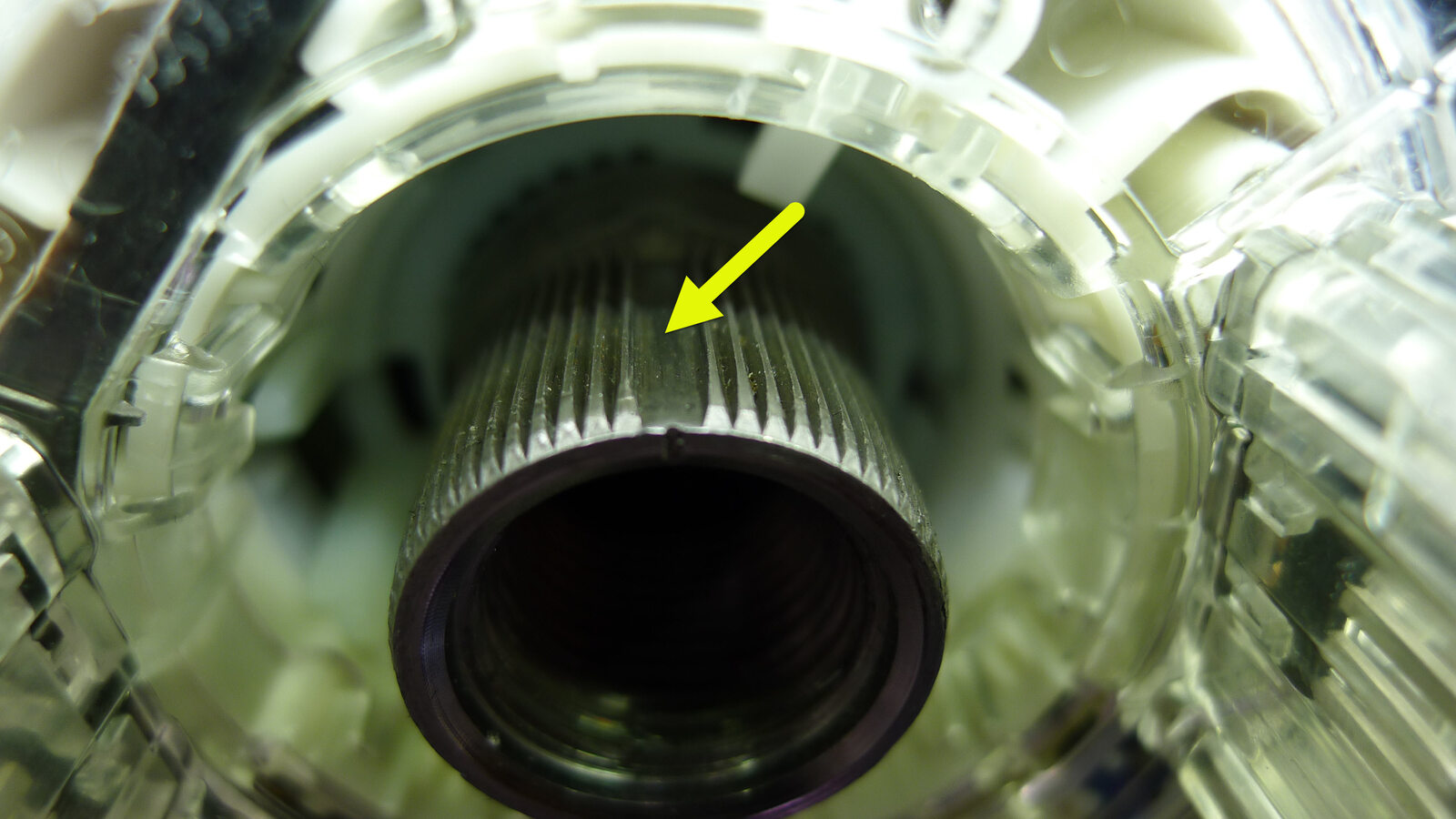
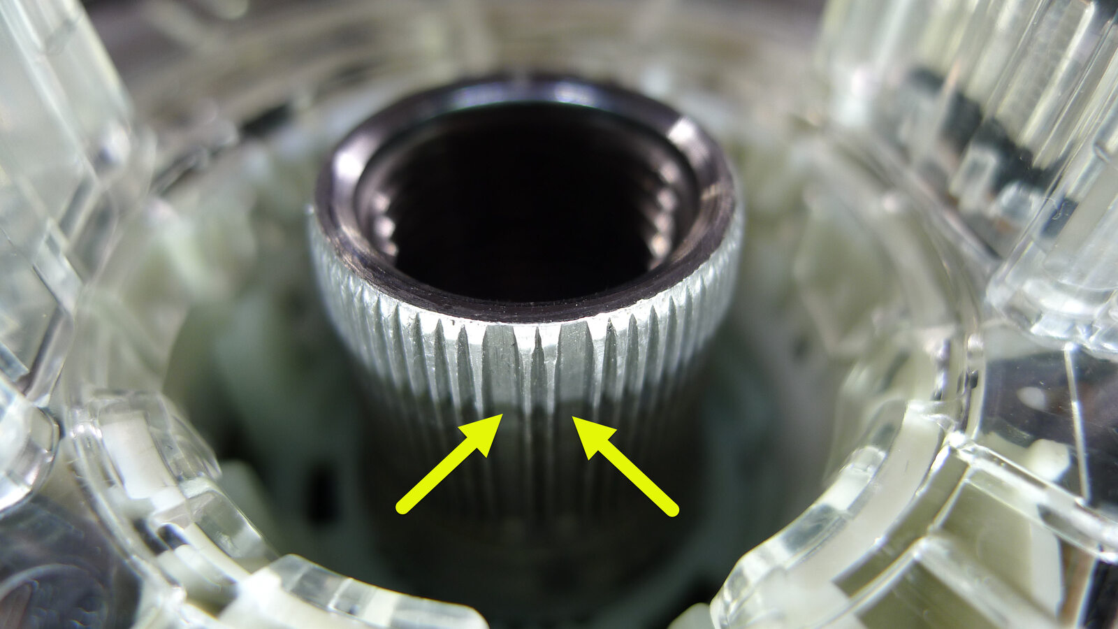
Install steering wheel
注Note that the steering wheel is splined to the column and can only be installed in the correct position
-
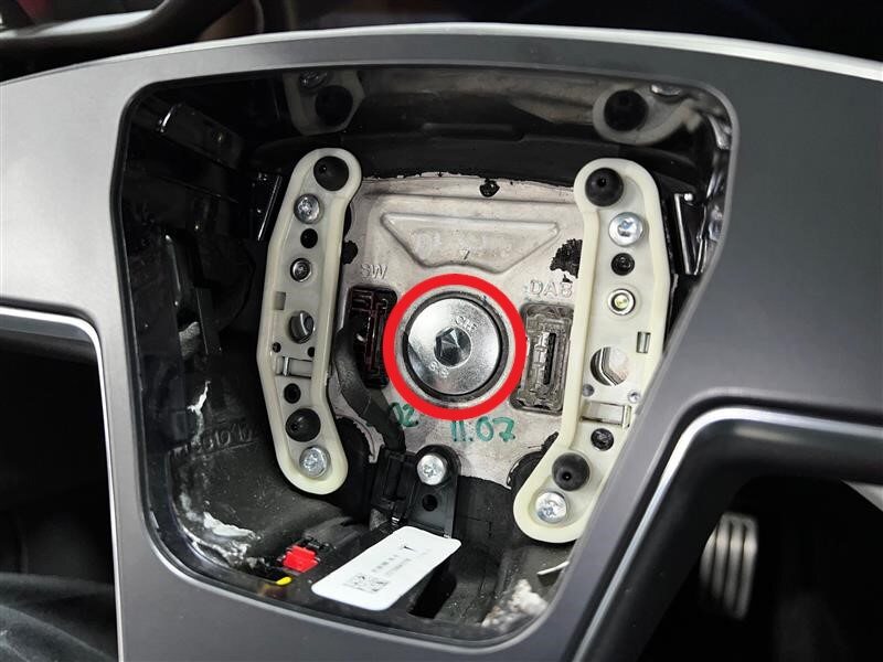
Install bolt securing steering wheel to steering column
注1x patch bolt, 10mm allen, 80 Nm, Install new patch bolt
-
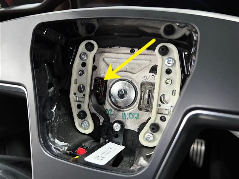
Secure steering wheel connector
注1x connector
-
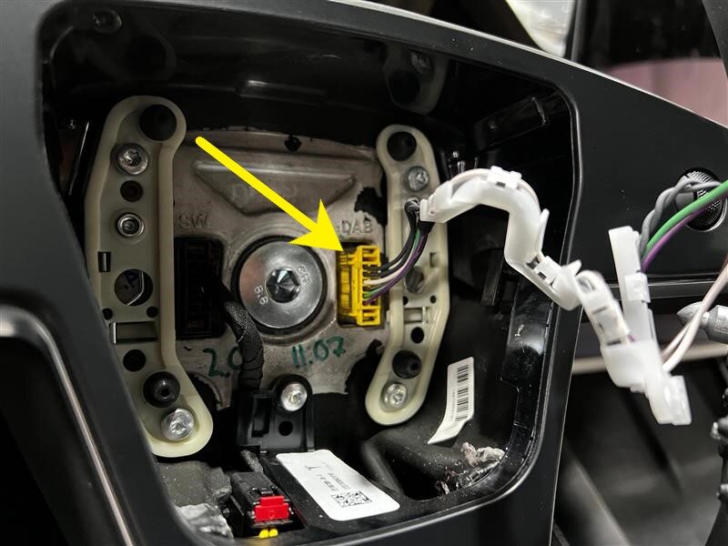
Secure driver air bag connector
注1x connector
-
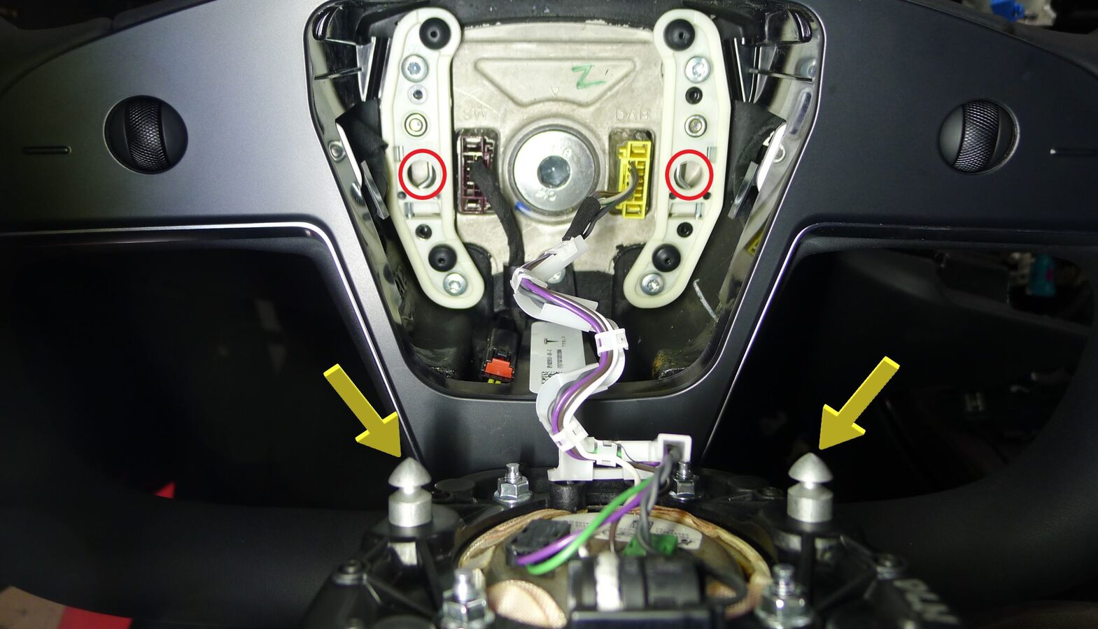
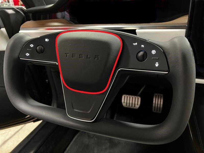
Install driver air bag assembly to yoke steering wheel
注2x datums, 2x spring clip, Position driver air bag onto yoke steering wheel, Align datums onto the clips, Press down on one side of the air bag until clip is fully seated, then repeat on other side, You should hear an audible click, Perform pull test on each side of driver air bag assembly, Confirm the gap and space between driver air bag assembly to yoke steering wheel is symmetrical

-
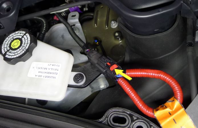
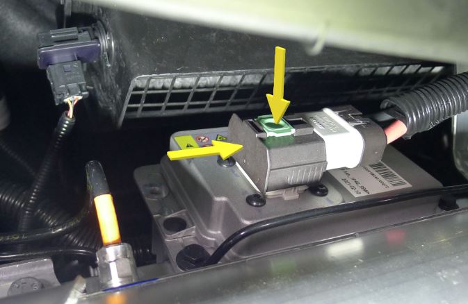
Connect the First Responder Loop and LV battery connector.
-
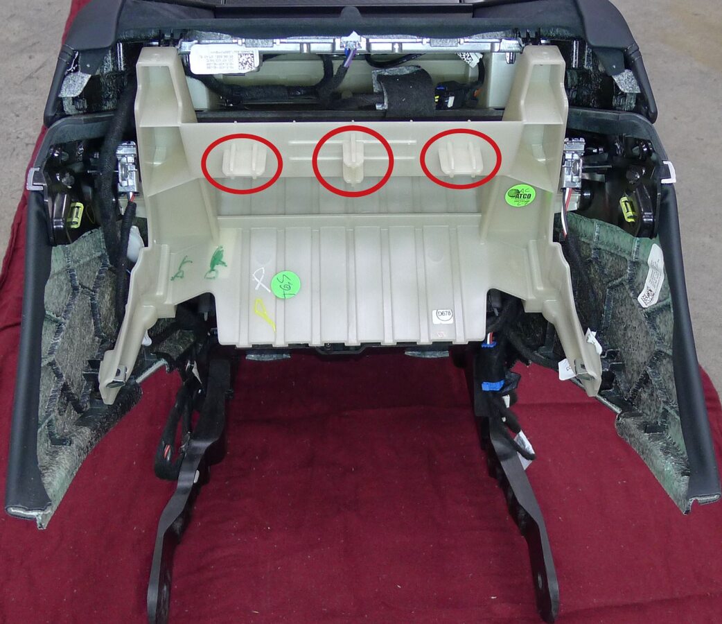
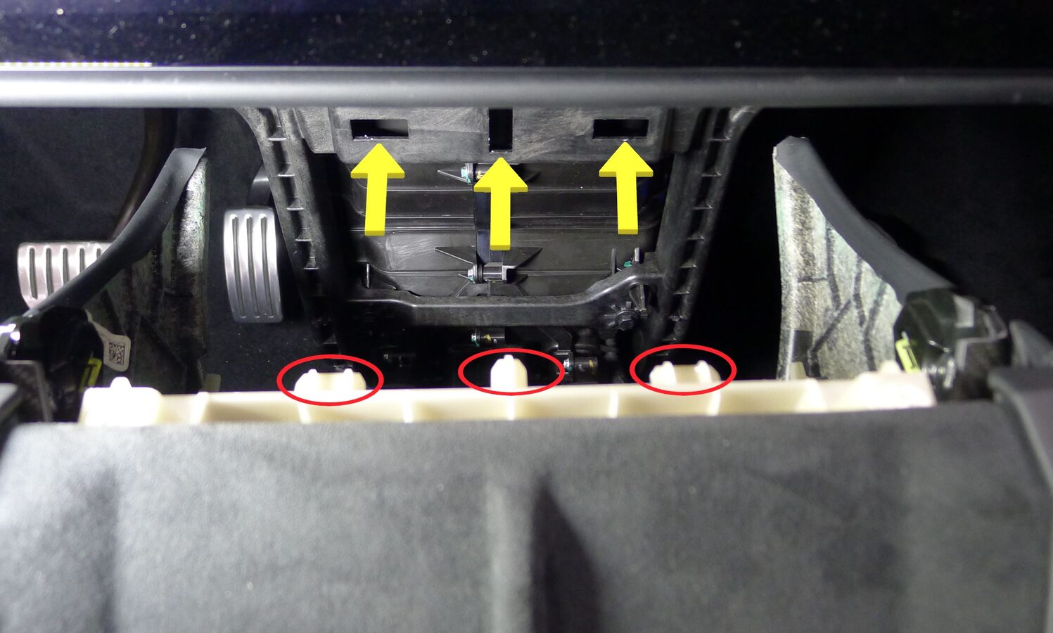
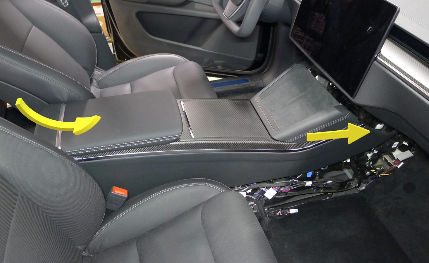
Install console assembly
注3x datums, Carefully maneuver front of assembly under and into IP carrier and lower rear into place, Align datums into IP carrier and engage forward, Recommend assistance if needed
-
Secure LH center console lower bracket to IP carrier
注1x bolt, 10mm, 10 Nm

-
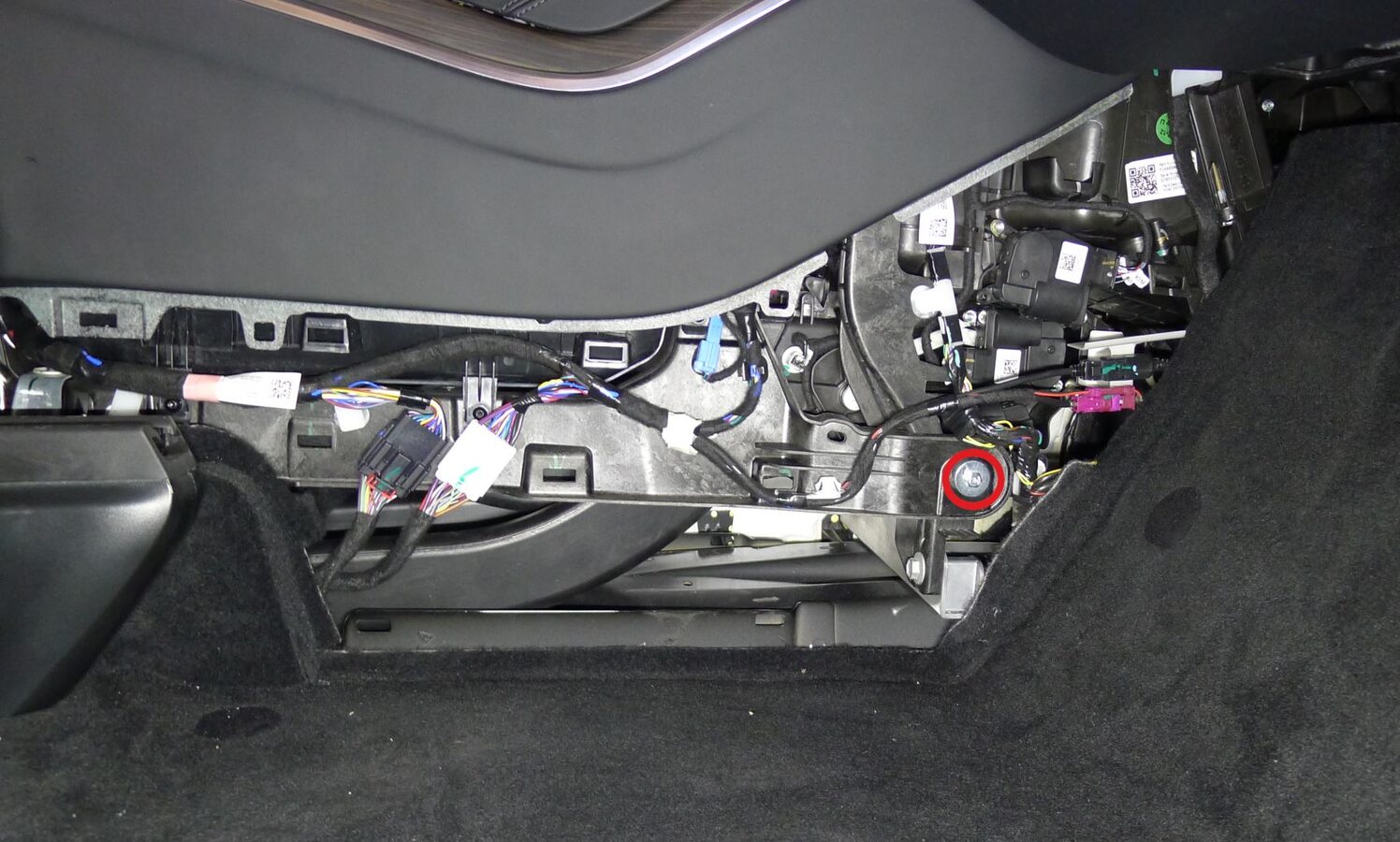
Secure RH center console lower bracket to IP carrier
注1x bolt, 10mm, 10 Nm
-
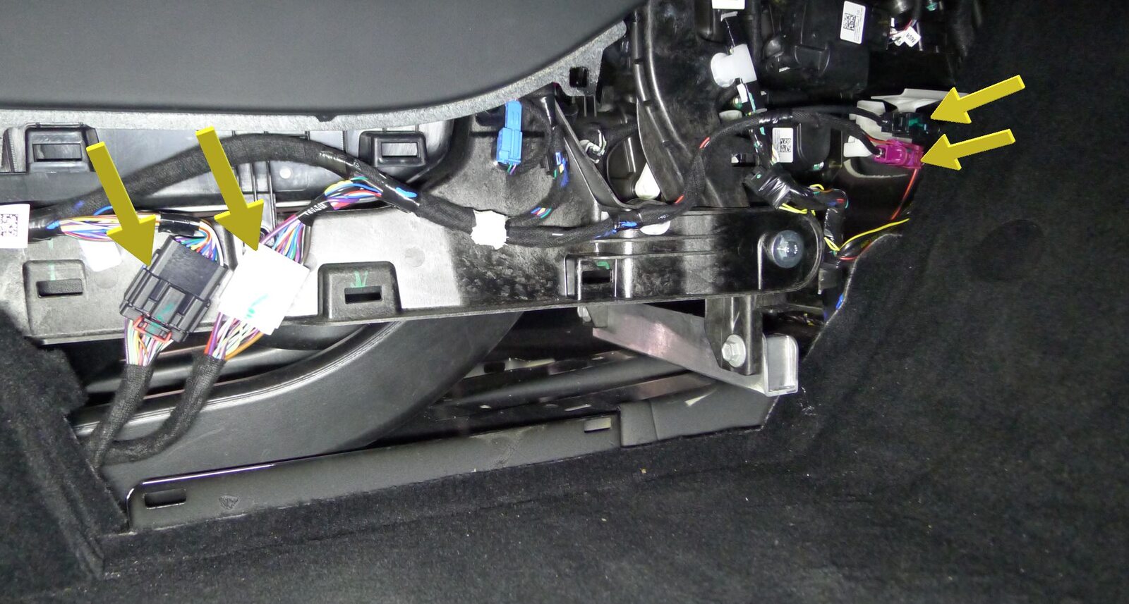
Secure center console connectors to body harness
注4x connectors, Ensure all connector locks engage
-
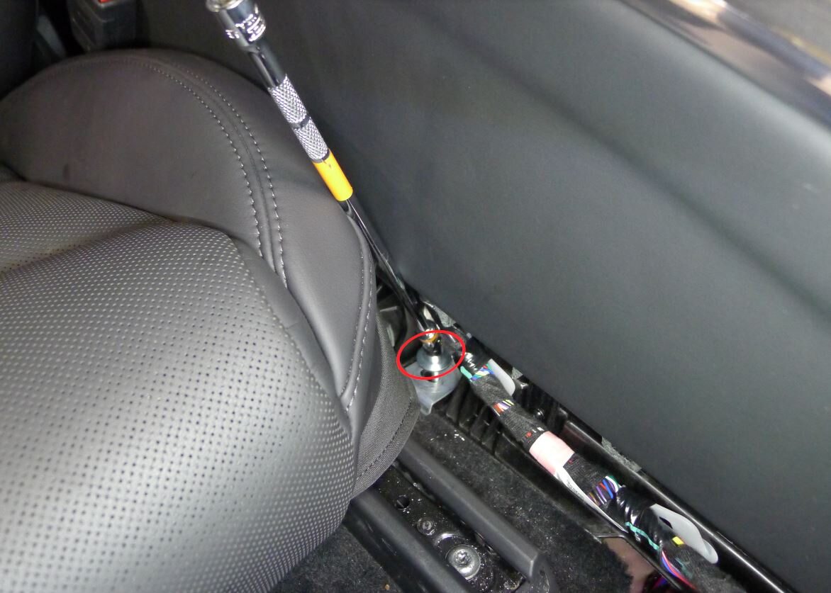
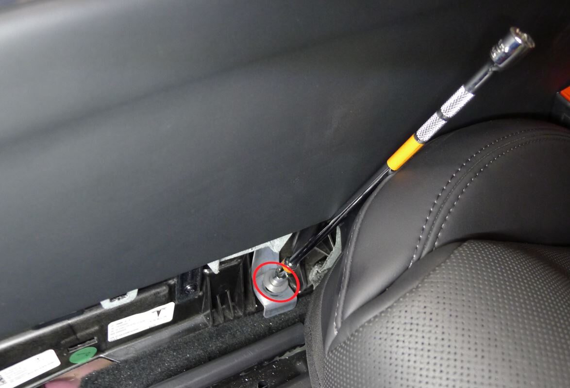
Secure LH and RH console carrier center bracket
注2x bolts, 10mm, 12 Nm
-
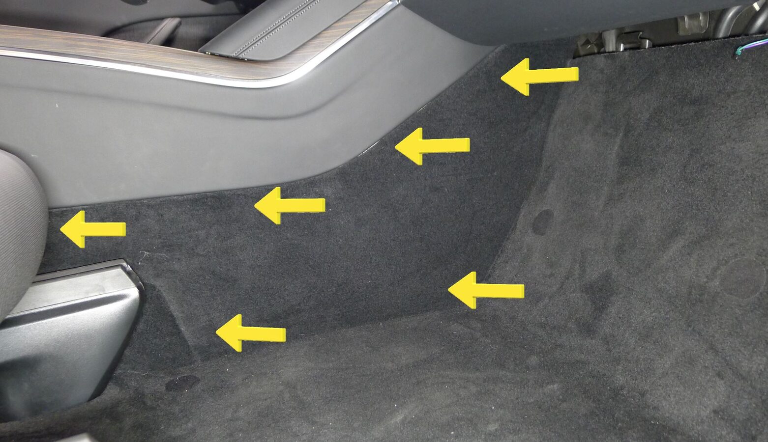
Install RH console side carpet
注11x clips, 2x datums

-
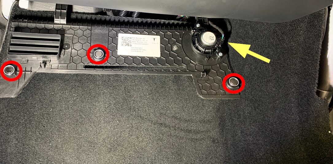
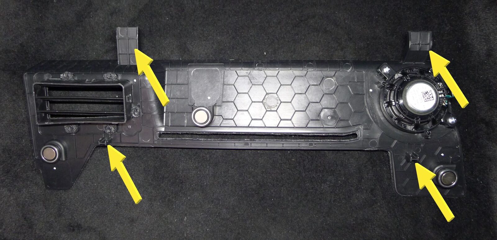
Install RH footwell cover
注3x magnets, 4x datums, 1x connector
-
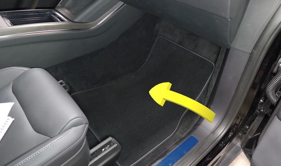
Install RH front floor mat
-
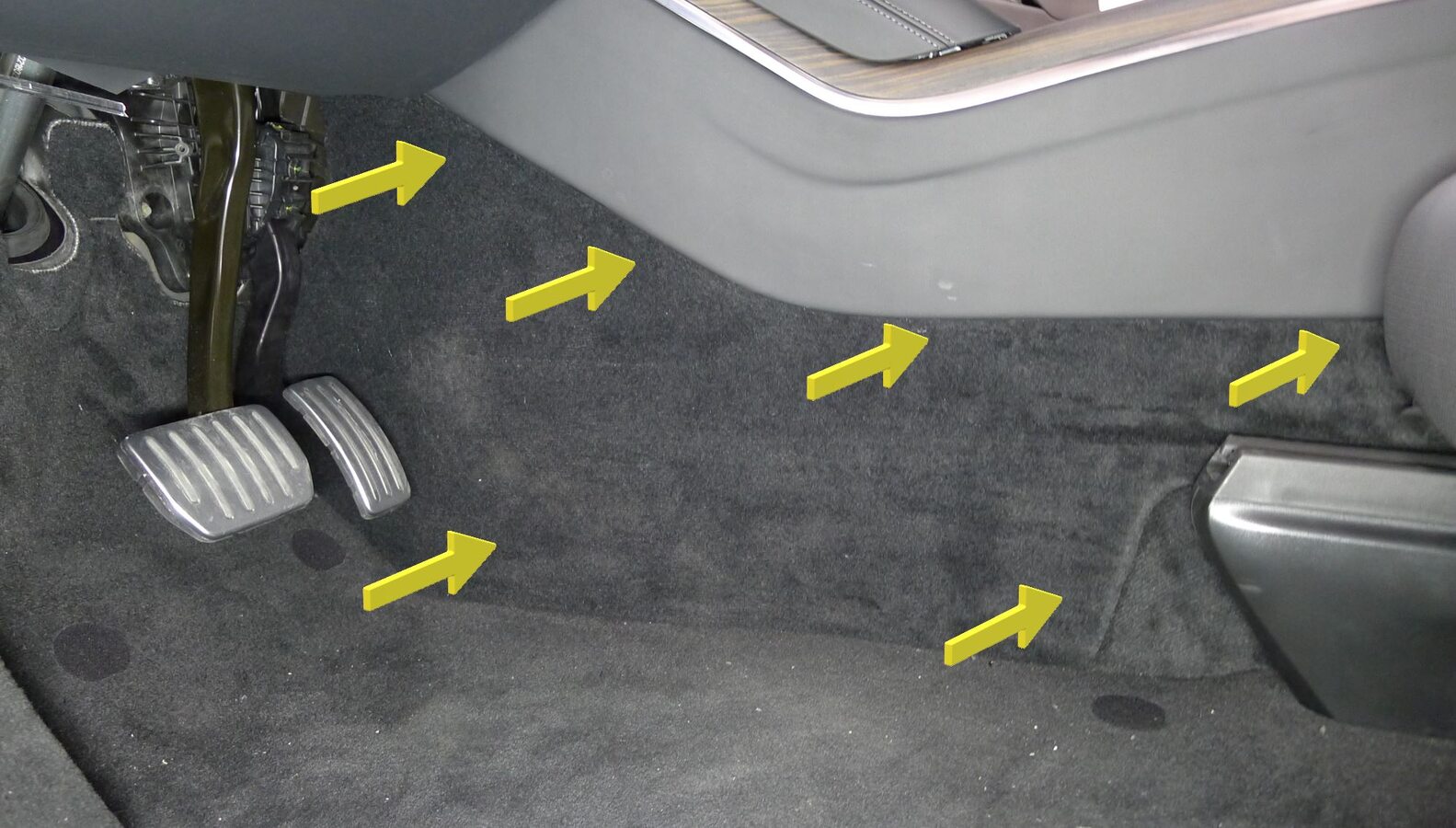
Install LH console side carpet
注11x clips, 2x datums
-
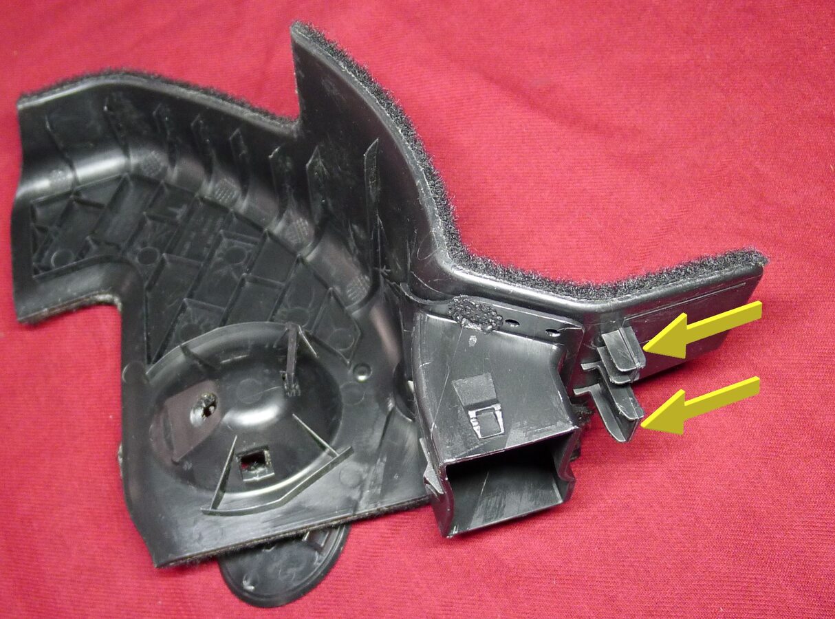
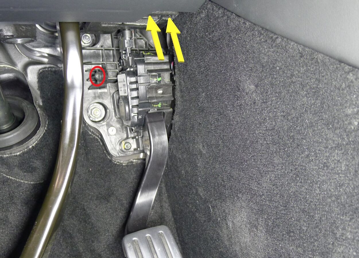
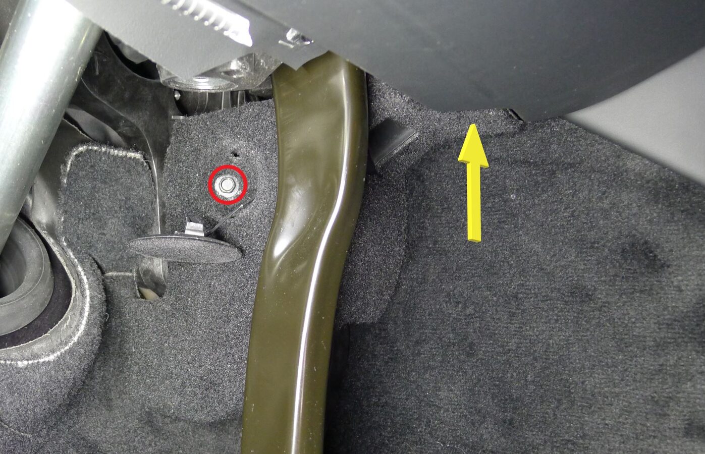
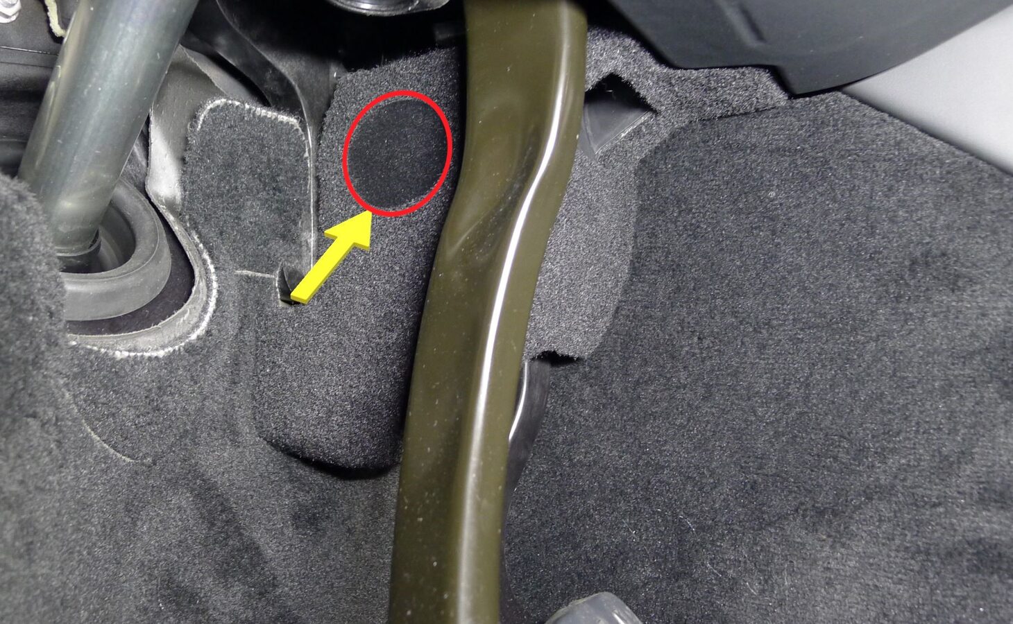
Install LH inboard footwell cover
注1x cover, 1x clip, 1x datum, 1x screw, 8 mm, 1 Nm, Align datums and footwell vent before installing screw
-
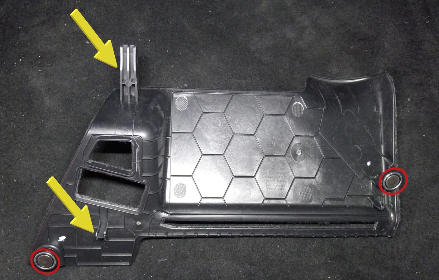
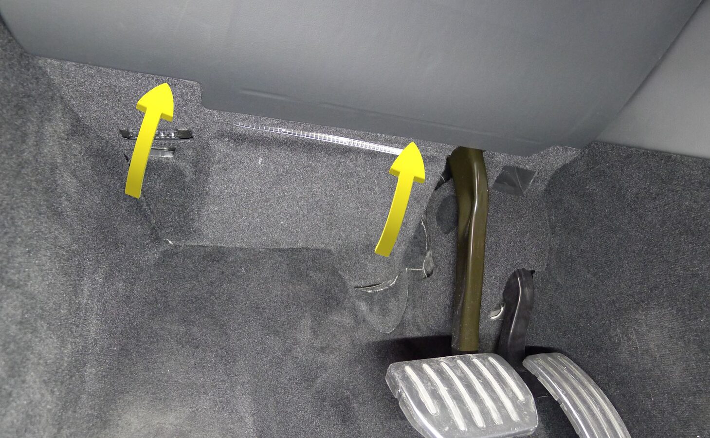
Install LH outboard footwell cover
注2x magnets, 2x datums
-
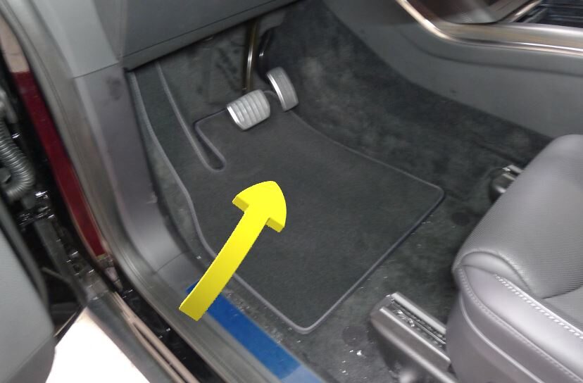
Install LH front floor mat
-
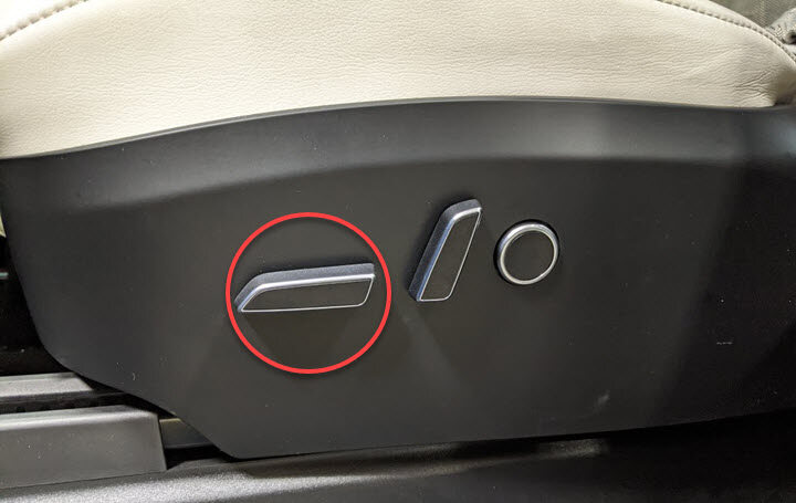
Move LH front seat forward
-
Raise LH front seat backrest

-
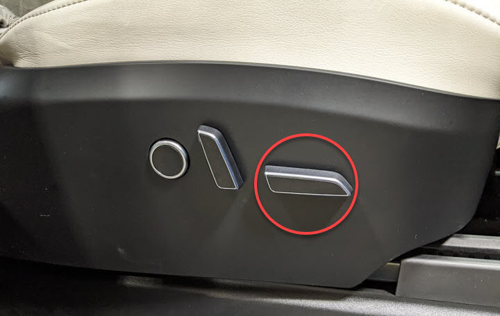
Move RH front seat forward
-
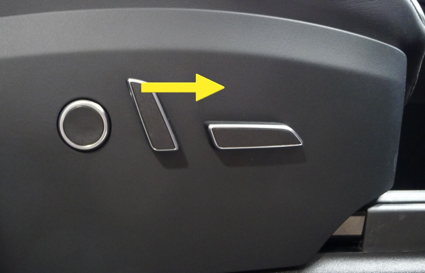
Raise RH front seat backrest
-
Secure LH and RH rear console carrier
注2x bolts, 10mm, 12 Nm
-
Install console back panel assembly
注1x connector
-
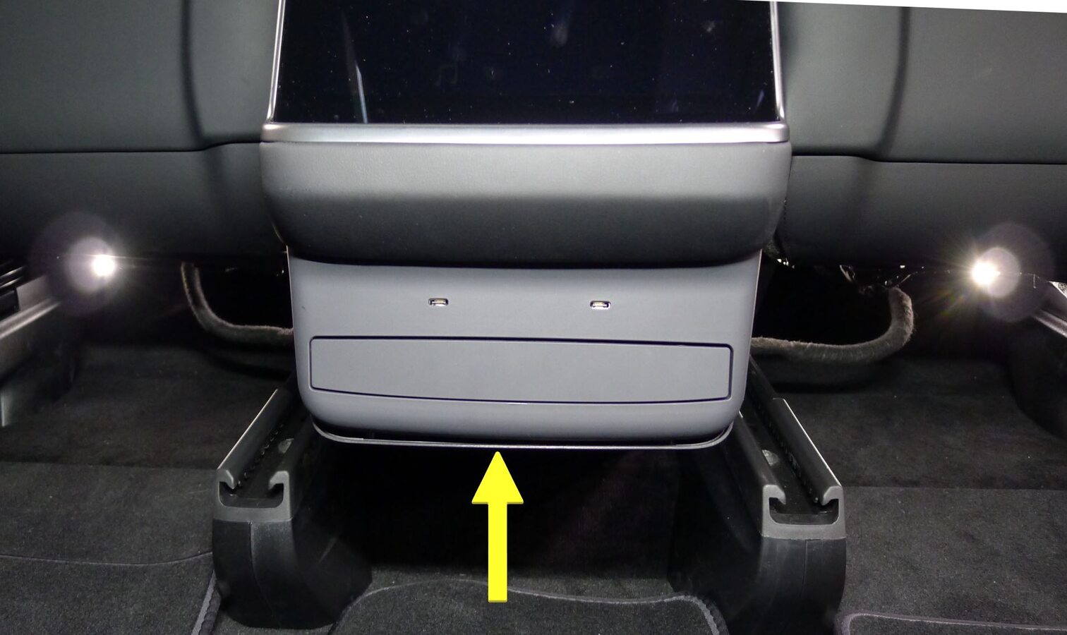
Secure console back panel assembly
注6x clips, 7x datums, Engage bottom clips first due to forward facing alignment
- Move the RH front seat to its original position.
- Move the LH front seat to its original position.
-
Unlock Gateway
注After vehicle has been put into "Service Mode", place keycard on center console to turn on drive rails, hold down the brake pedal, while keep pressing right hand signal button simultaneously for at least 10 seconds, "GTW UNLOCKING" should pop up on the UI right next to the VIN during these 10 seconds, once gateway is unlocked "GTW UNLOCKED 5400" will be displayed on the UI next to the VIN, the gateway will remain unlocked for 90 minutes, follow steps on Toolbox article #5582900 for any additional information
-
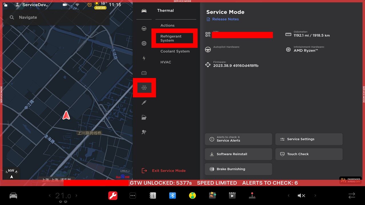
Navigate to Refrigerant System through UI
注Select Service Mode > Thermal > Refrigerant System
-
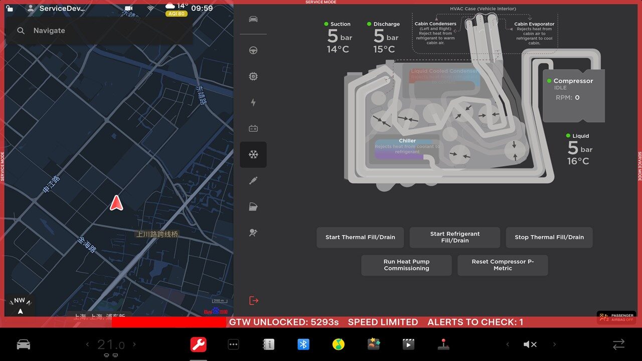
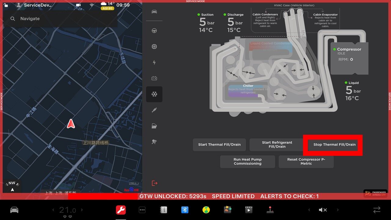
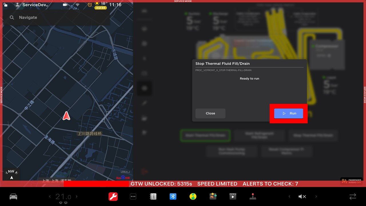
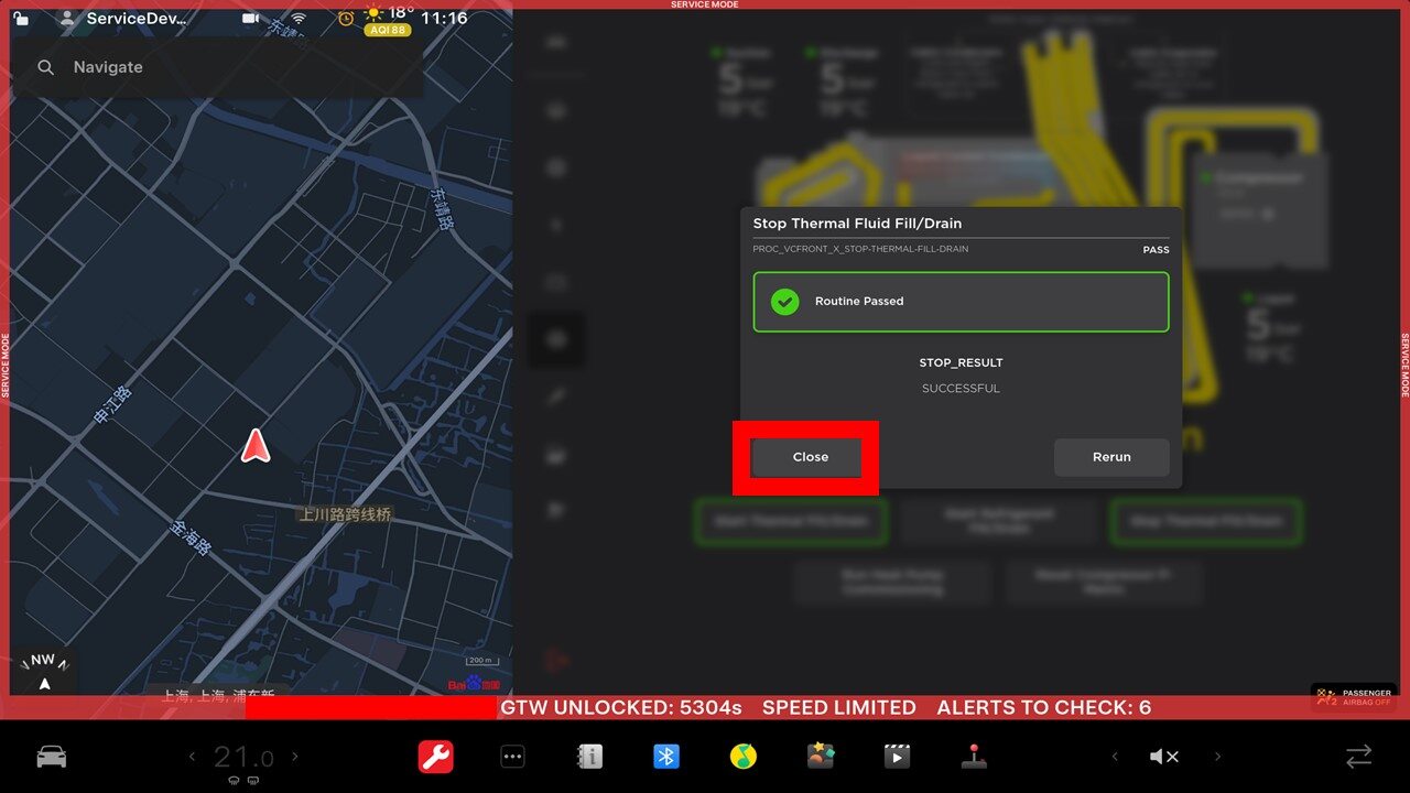
Select "Stop Thermal Fill Drain" through UI
注Select Thermal > Refrigerant System > Stop Thermal Fill Drain , Click Run, Close once routine is completed
-
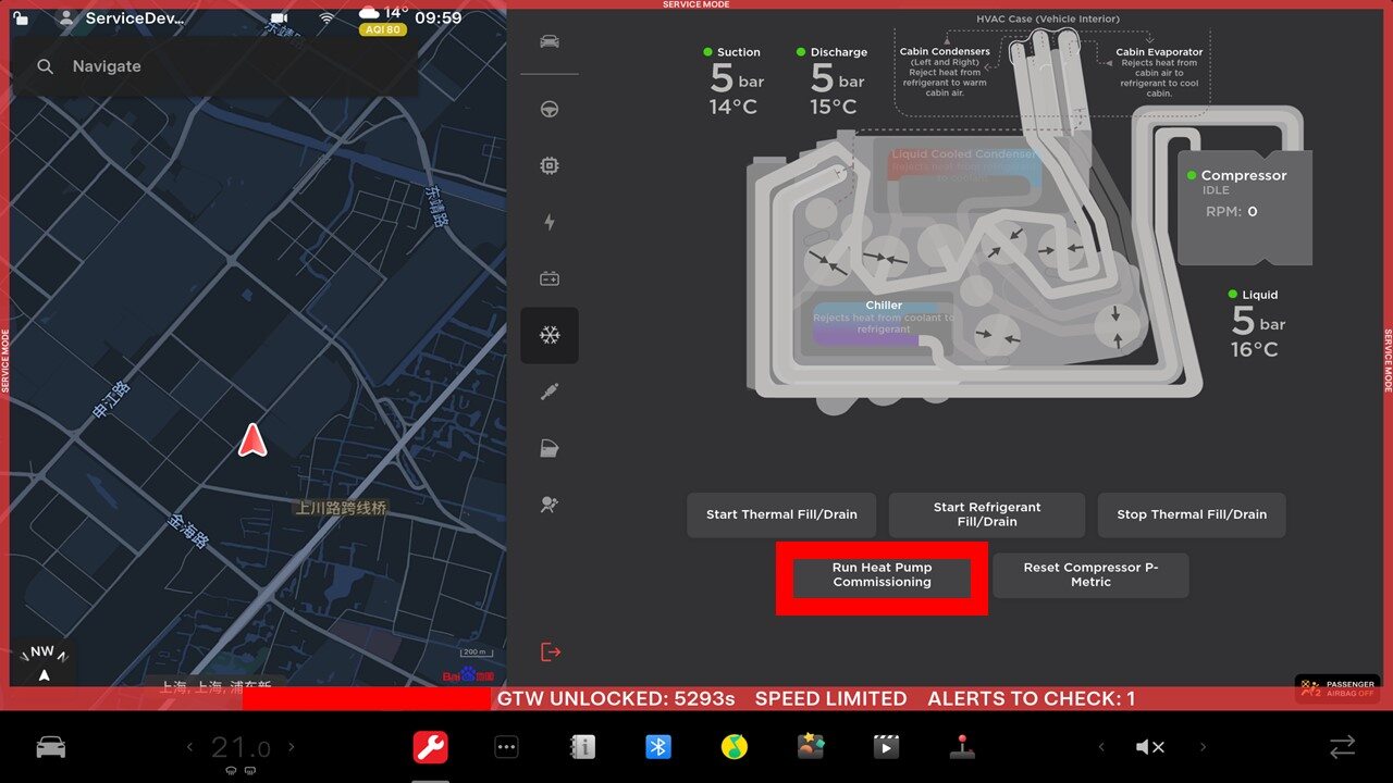
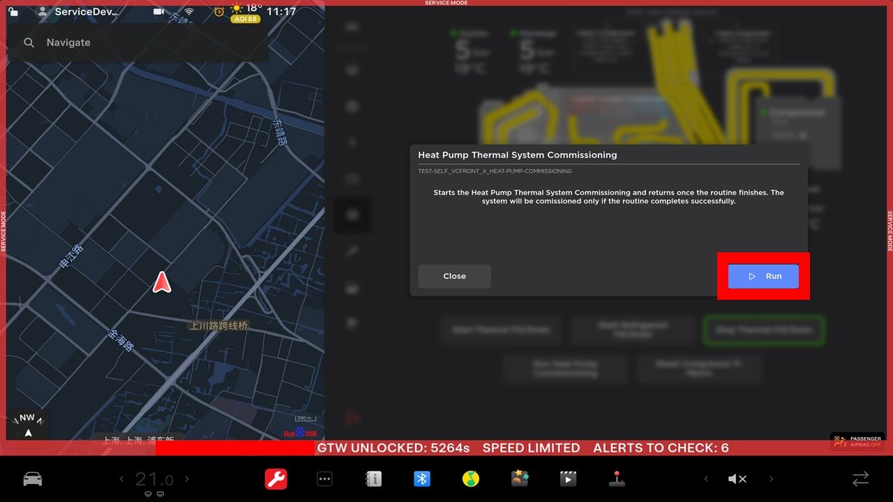
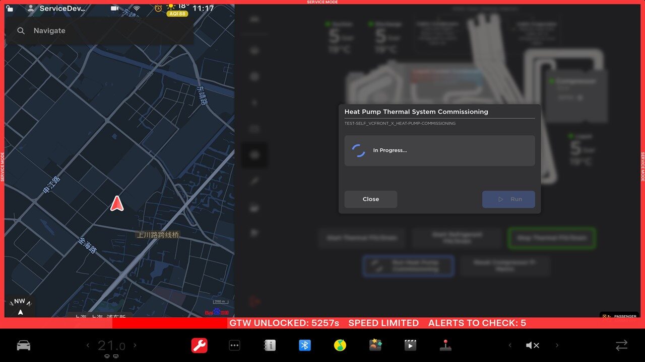
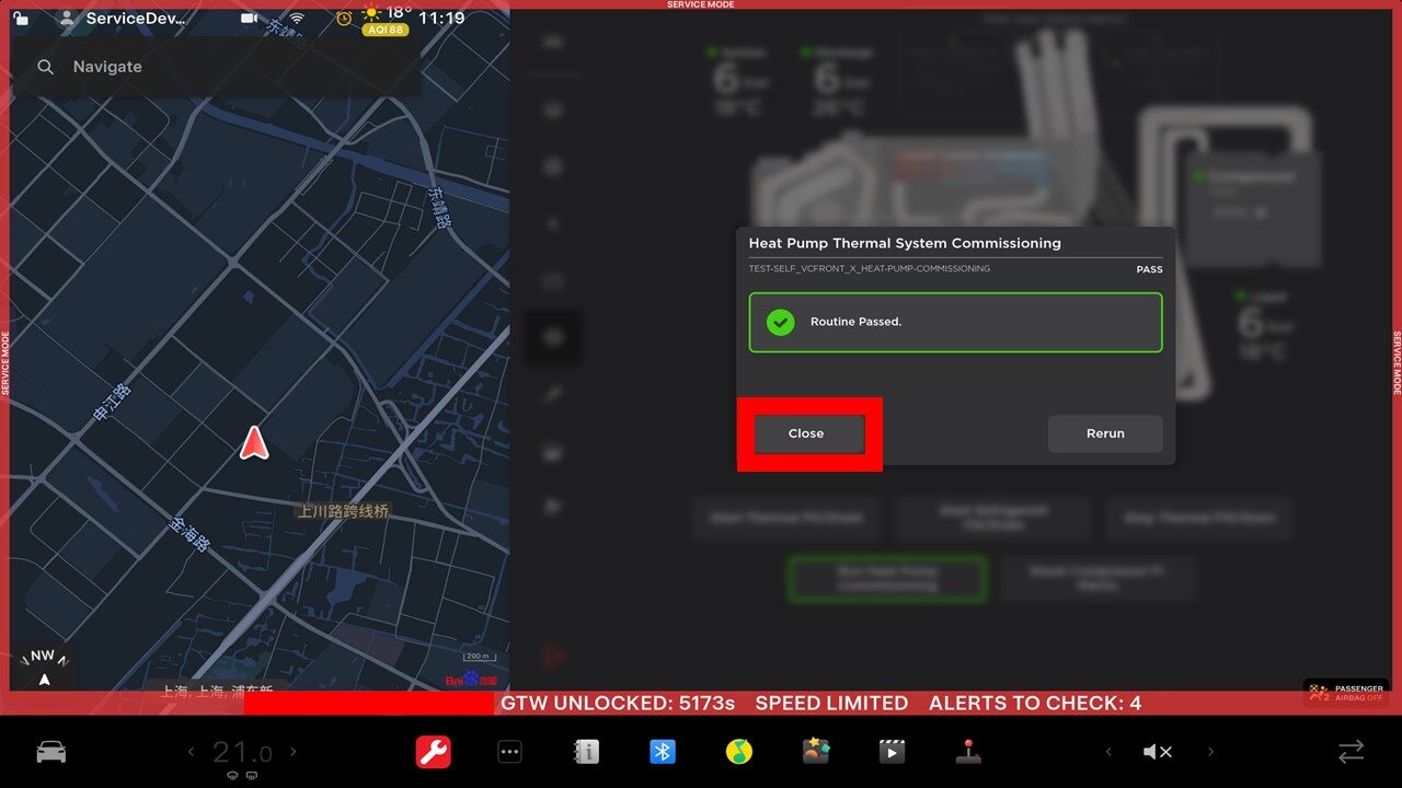
Perform Heat Pump Commissioning through UI
注Select Thermal > Refrigerant System > Run Heat Pump Commissioning, click Run, close once routine is passed
-
Remove AC hoses from vehicle
-
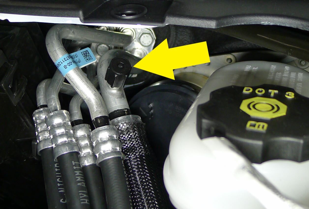
Install caps onto AC ports
注2x caps
-
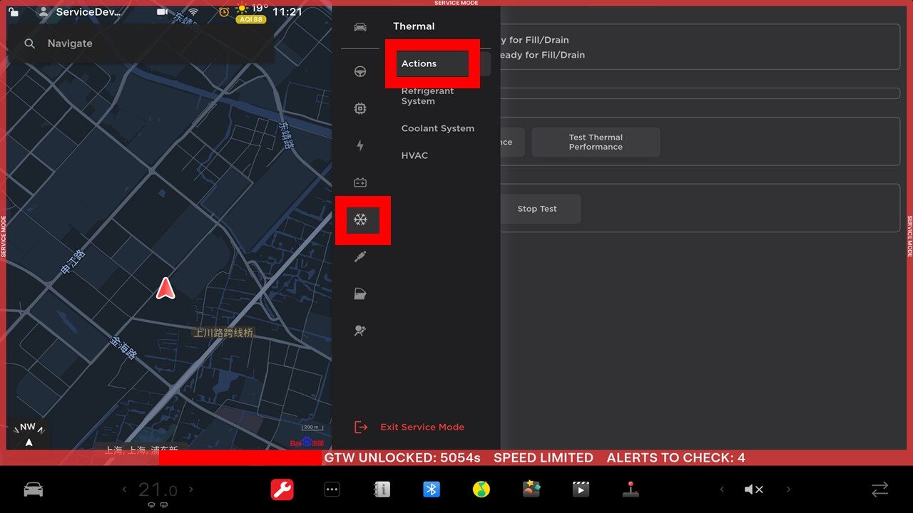
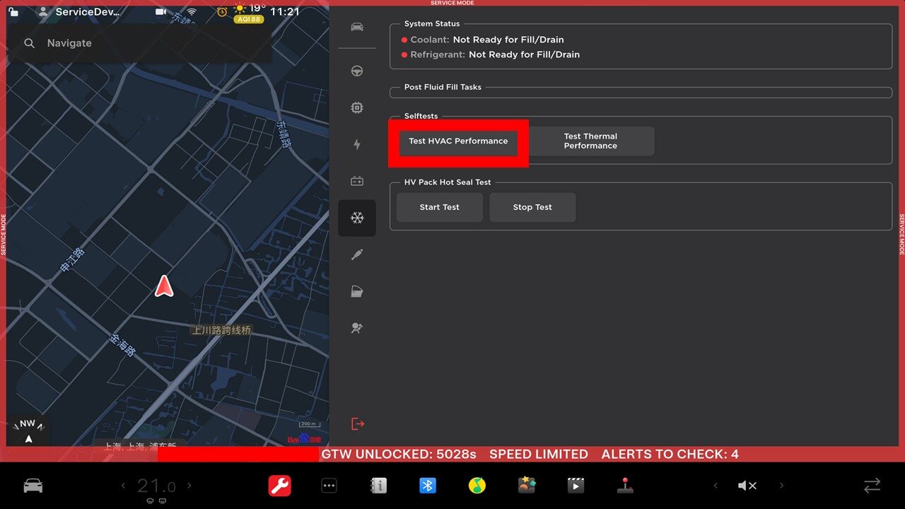
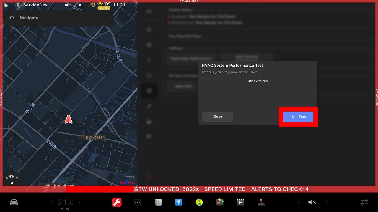
Test HVAC Performance through UI
注Select Thermal > Actions > Test HVAC Performance, click Run, close once routine passed
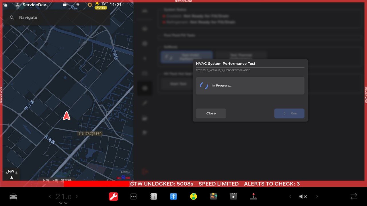
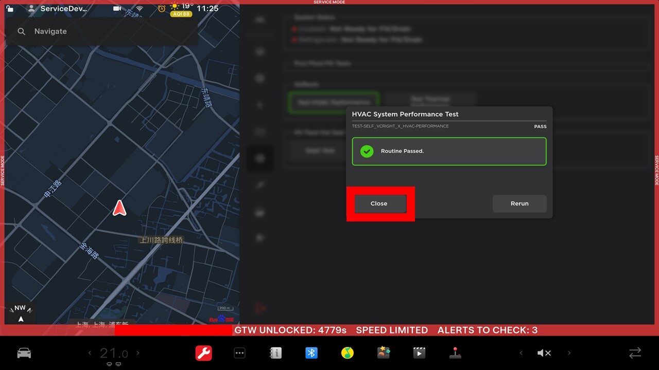
-
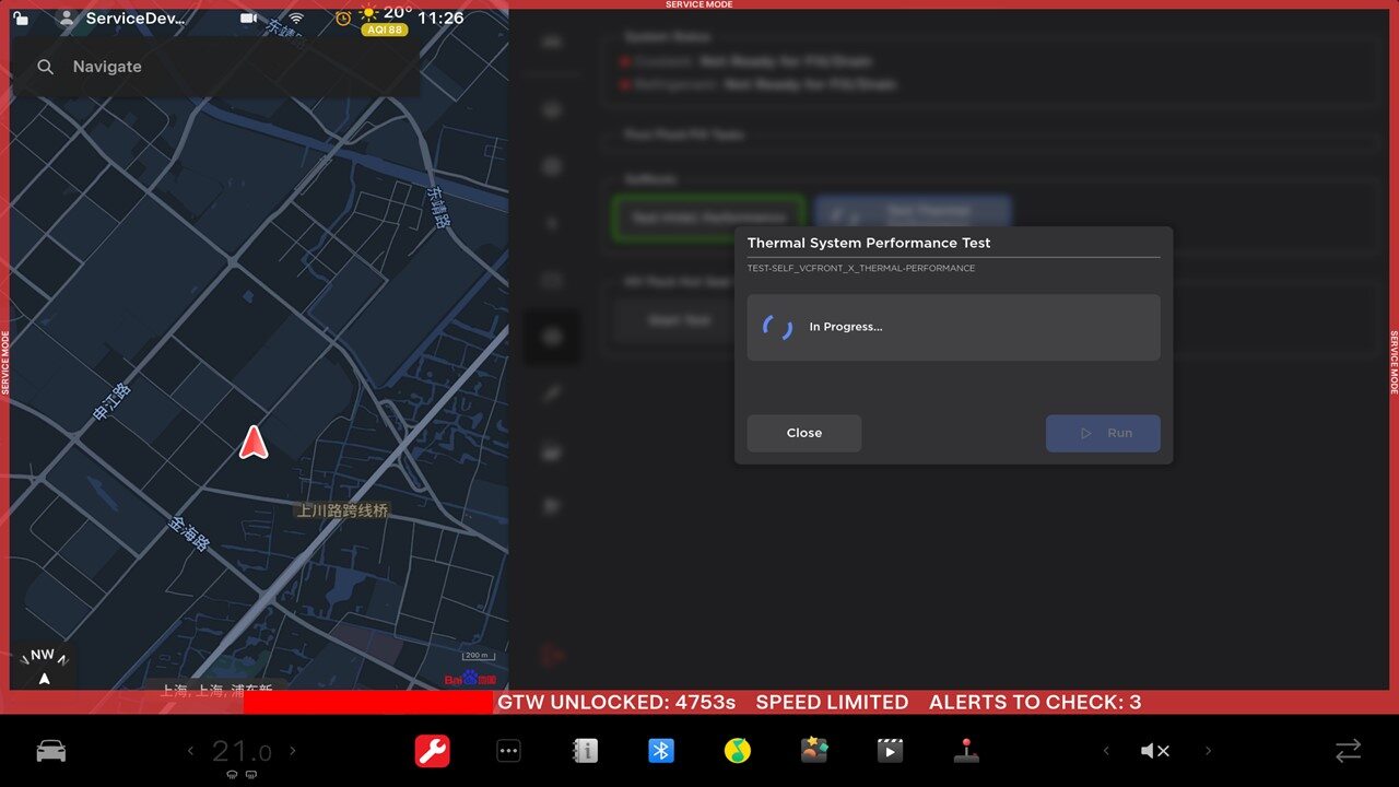
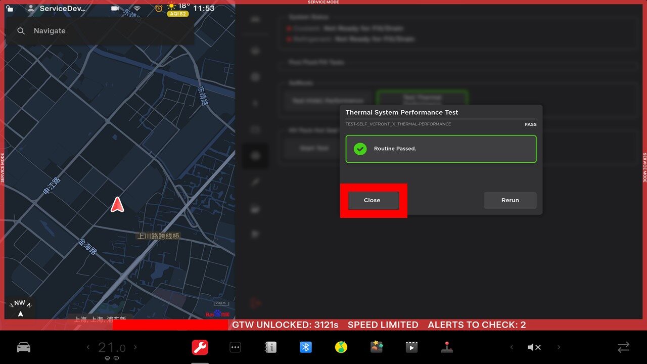
Test Thermal Performance through UI
注Select Thermal > Actions > Test Thermal Performance, click Run, close once routine is completed
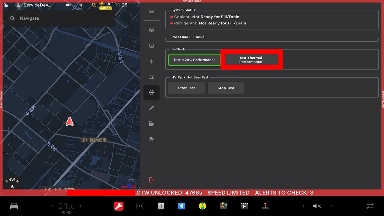
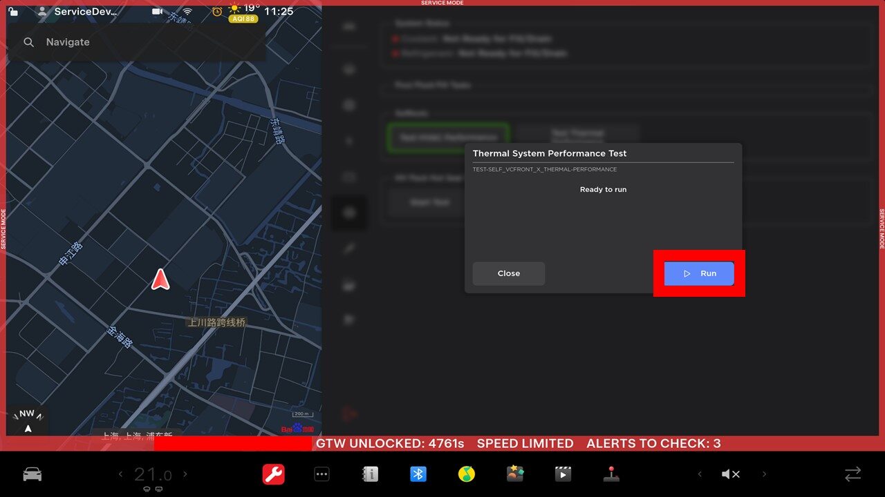
-
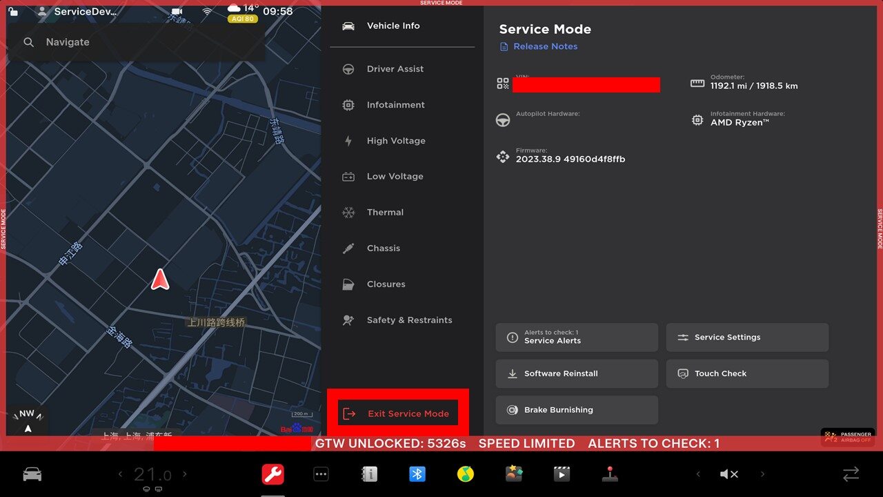
Exit Service Mode through UI
注Press and hold the Exit Service Mode button for 3 seconds
-
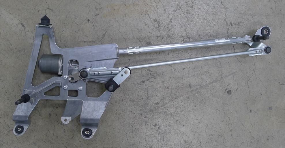
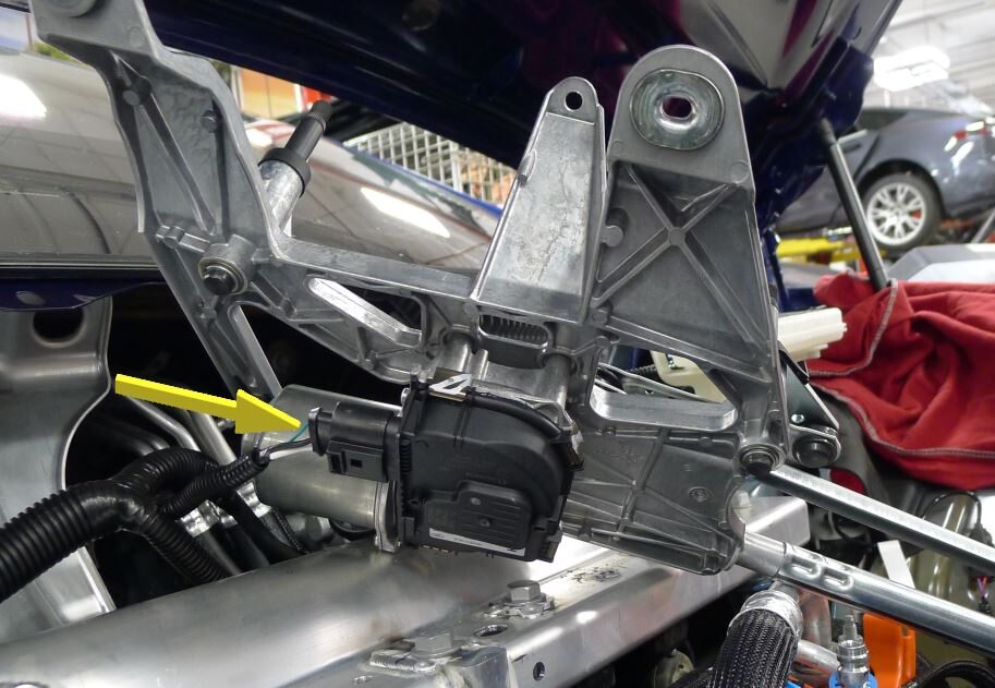
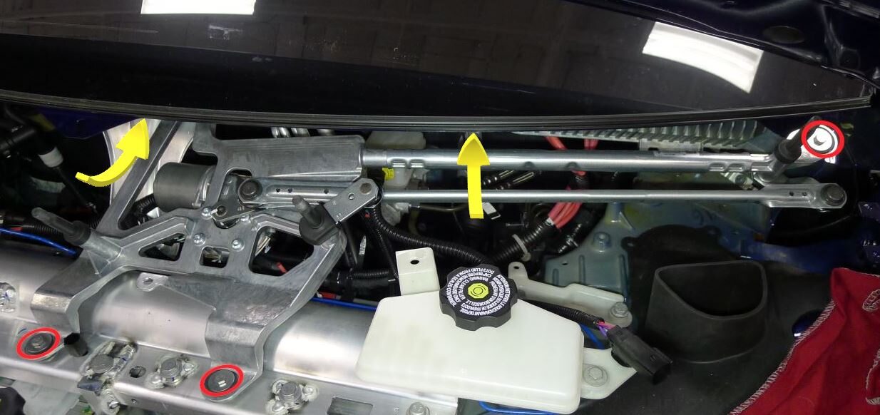
Install wiper module
注3x bolts, 10mm, 9 Nm, 1x connector, Secure connector before install, Rotate module rearward and up into place
-
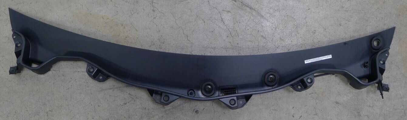
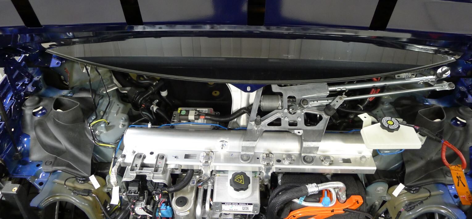
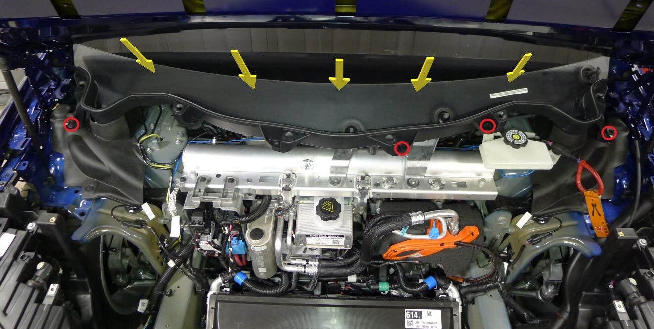
Install wiper cowl screen panel
注4x push clips, Secure cowl into lower windshield channel
-
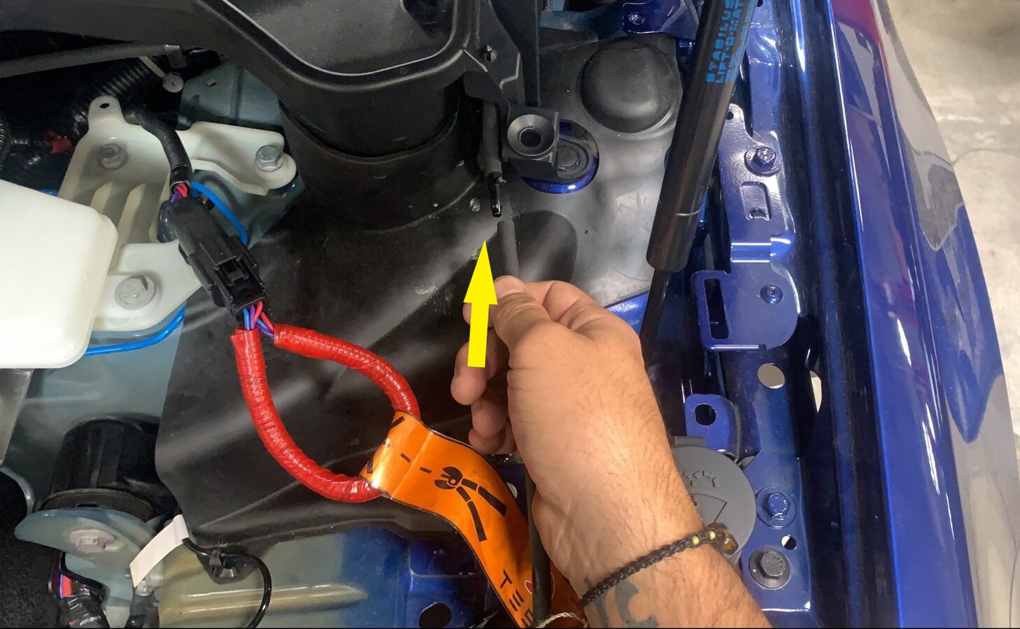
Connect cowl screen washer supply hose
注1x hose
-
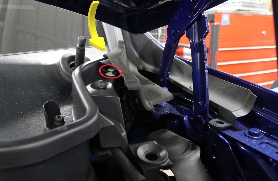
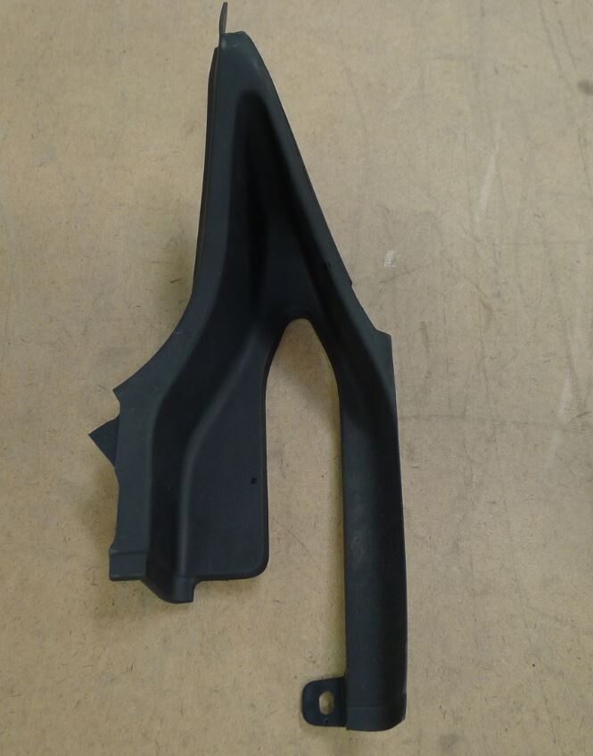
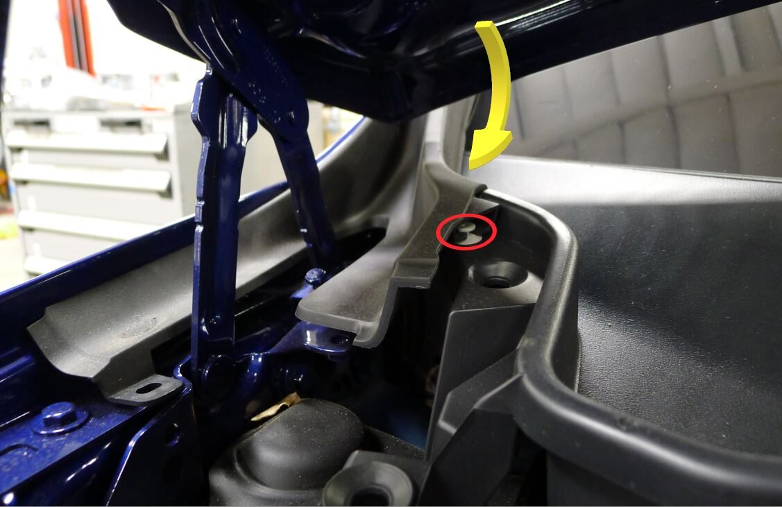
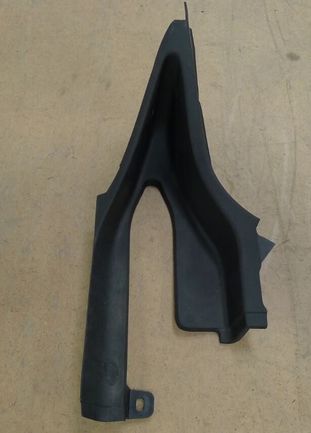
Install LH outer hood hinge cover
注1x clips
-
Install RH outer hood hinge cover
注1x clips
-
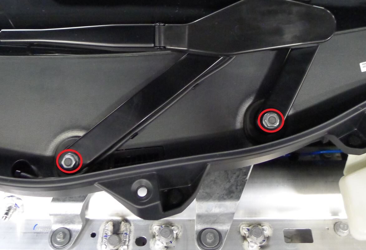
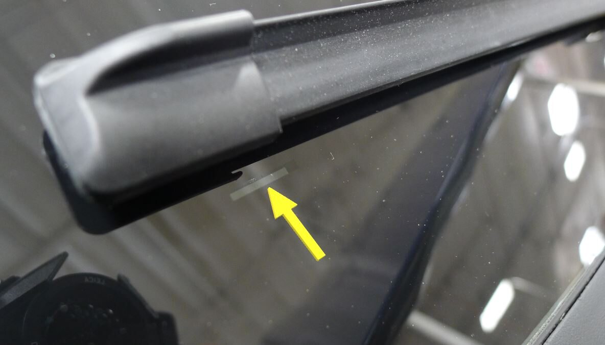
Install RH wiper arm assembly
注2x nuts, 15mm, 32 Nm, Line up wiper to reference mark on windshield
-
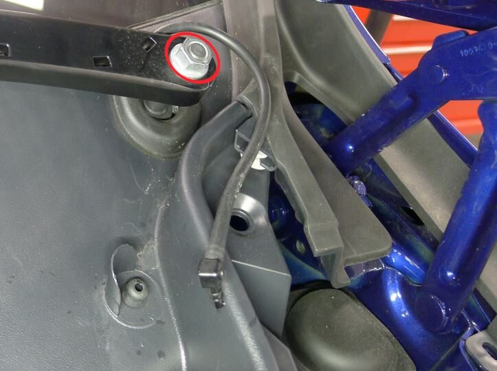
Install LH wiper arm assembly
注1x nut, 15mm, 32 Nm
-
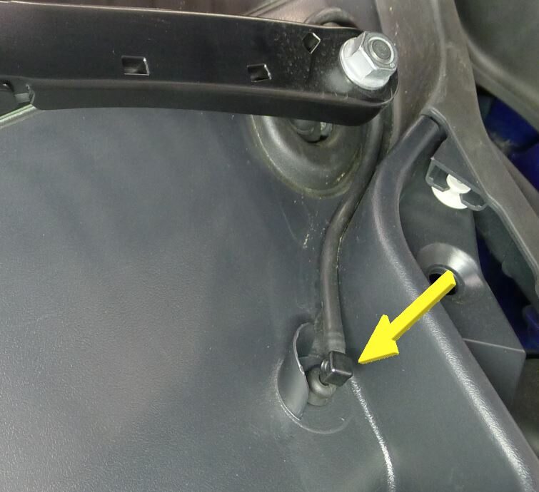
Secure LH wiper arm hose nozzle
注1x hose, Hose is routed above the arm pivot
-
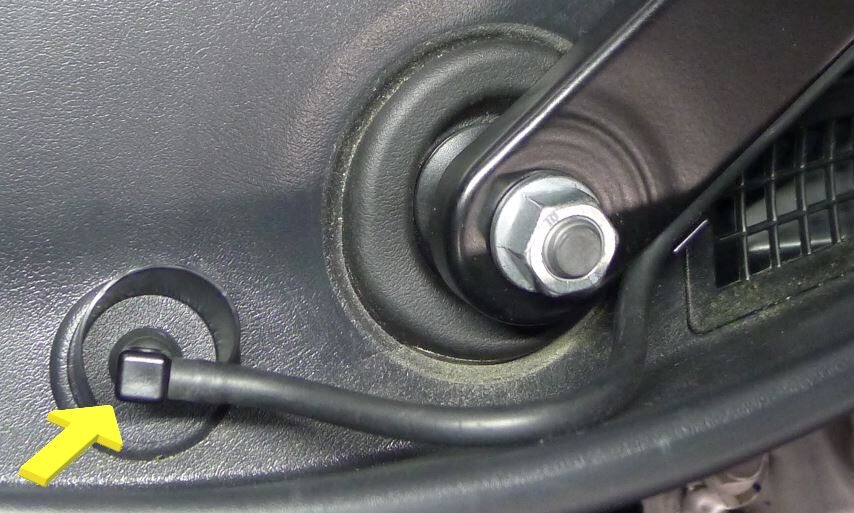
Secure RH wiper arm hose nozzle
注1x hose, Hose is routed below the arm pivot
-
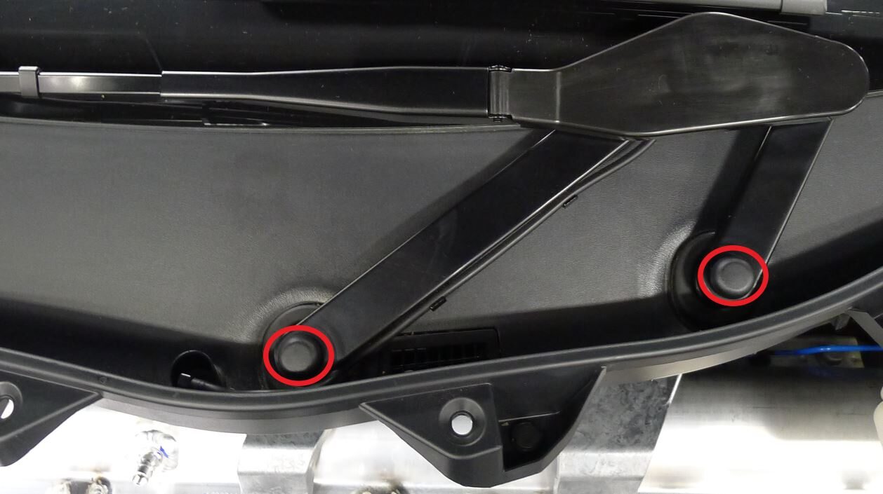
Install RH wiper arm nut covers
注2x cover
-
Install LH wiper arm nut cover
注1x cover
-
Install the underhood storage unit.
-
Install the underhood storage unit carpet.
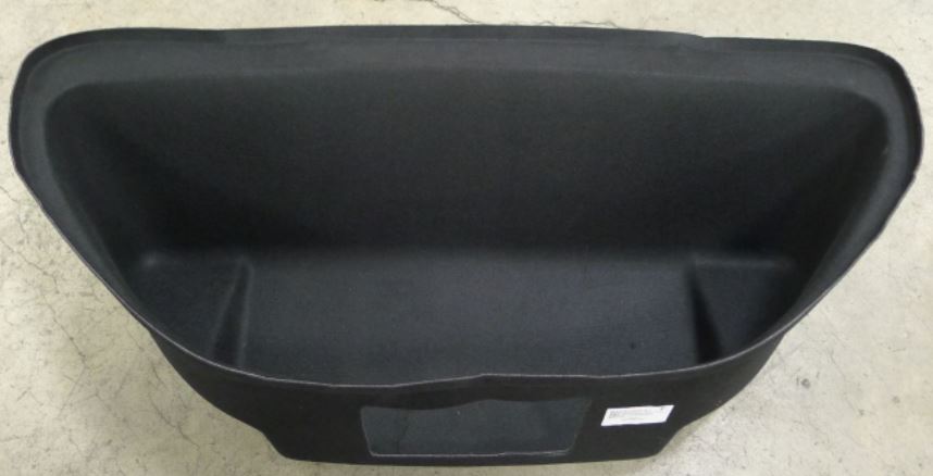
-
Install the underhood storage unit access panel.
-
Install the front underhood apron.
-
Install the LH underhood apron.
-
Install the RH underhood apron.
-
Install the rear underhood apron.
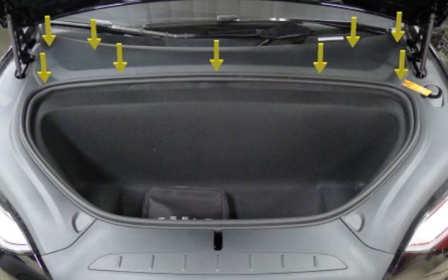
- Close the hood.
-
Adjust steering column back to original position
注Via UI>Controls>Steering , Use left steering wheel scroll wheel to adjust steering column
-
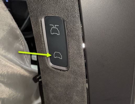
Calibrate the RH falcon wing door.
- Close the RH front door.
-
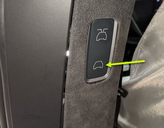
Calibrate the LH falcon wing door.
- Raise both front windows.
- Close the LH front door.


